

Digital Delay/Pulse Generator - Stanford Research Systems
Digital Delay/Pulse Generator - Stanford Research Systems
Digital Delay/Pulse Generator - Stanford Research Systems
- No tags were found...

You also want an ePaper? Increase the reach of your titles
YUMPU automatically turns print PDFs into web optimized ePapers that Google loves.
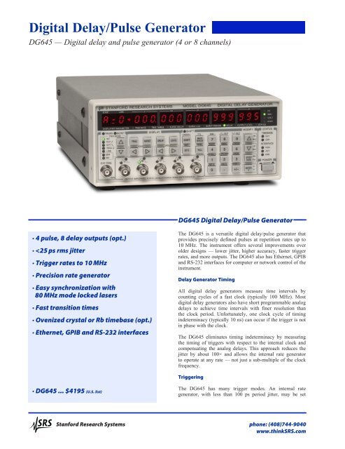
<strong>Digital</strong> <strong>Delay</strong>/<strong>Pulse</strong> <strong>Generator</strong>DG645 — <strong>Digital</strong> delay and pulse generator (4 or 8 channels)DG645 <strong>Digital</strong> <strong>Delay</strong>/<strong>Pulse</strong> <strong>Generator</strong>· 4 pulse, 8 delay outputs (opt.)·
DG645 <strong>Digital</strong> <strong>Delay</strong>/<strong>Pulse</strong> <strong>Generator</strong>from 100 µHz to 10 MHz with 1 µHz resolution. An externaltrigger input, with adjustable threshold and slope, can triggera timing cycle, a burst of cycles, or a single shot. A singleshot can be triggered with a key press. A line trigger operatessynchronously with the AC mains. A rear-panel trigger inhibitinput can disable the trigger or any of the pulse outputs duringa timing cycle.The DG645 supports a number of complex triggeringrequirements via a trigger holdoff and prescaling feature.Trigger holdoff sets the minimum time between successivetriggers. This is useful if a trigger event in your applicationgenerates a significant noise transient that needs time to decayaway before the next trigger is generated. Trigger holdoff canalso be used to trigger the DG645 at a sub-multiple of theinput trigger rate.Trigger prescaling enables the DG645 to be triggeredsynchronously with a much faster source, but at a sub-multipleof the original trigger frequency. For example, the DG645 canbe triggered at 1 kHz, but synchronously with a mode lockedlaser running at 80 MHz, by prescaling the trigger input by80,000. Furthermore, the DG645 also contains a separateprescaler for each front-panel output, enabling each output tooperate at a sub-multiple of the trigger rate.Front-Panel OutputsFront-panel outputs (50 ns/div)There are five front-panel outputs: T 0 , AB, CD, EF andGH. The T 0 output is asserted for the duration of the timingcycle. The leading edge of T 0 is the zero time reference. Theprogrammed delays (A, B, C, D, E, F, G and H) are set from0 s to 2000 s, with 5 ps resolution, to control the timing of theleading and trailing edges of the four pulse outputs.Each front-panel output can drive a 50 Ω load and has a 50 Ωsource impedance. Output amplitudes can be set from 0.5 to 5.0 V,and output offsets can range over ±2 VDC to source virtuallyany logic level (NIM, ECL, PECL, CMOS, etc.). Outputtransition times are less than 2 ns at any output amplitude.Rear-Panel OutputsOptional rear-panel outputs are available to support diverseapplications. Option 01 provides a T 0 output and eightprogrammed delays (A, B, C, D, E, F, G and H) at 5 Vlogic levels, with transition times less than 1 ns. Option 02provides these same outputs but as 30 V, 100 ns pulses withless than 5 ns transition times for timing distribution in highnoise environments. Option 03 provides eight combinatorialoutputs which deliver one to four pulses at 5 V logic levelswith less than 1 ns transition times. Each output has a 50 Ωsource impedance.Max. Error (after 1 yr.)Combinatorial outputs showing 3 ns, 5 ns and 10 nspulses with 1 ns transition times (5 ns/div)1 ms100 µs10 µs1 µs100 ns10 ns1 nsOCXO Timebase(opt. 4)Rubidium Timebase(opt. 05)Ideal External Timebase100 ps10 µs 100 µs 1 ms 10 ms 100 ms 1 s 10 s 100 s 1000 s<strong>Delay</strong>Standard TimebaseTiming error vs. programmed delay<strong>Stanford</strong> <strong>Research</strong> <strong>Systems</strong>phone: (408)744-9040www.thinkSRS.com
DG645 <strong>Digital</strong> <strong>Delay</strong>/<strong>Pulse</strong> <strong>Generator</strong>Jitter (rms)10 µs1 µs100 ns10 ns1 nsRubidium Timebase(opt. 05)Ideal External TimebaseOCXO Timebase(opt. 4)Standard Timebase100 ps10 ps10 µs 100 µs 1 ms 10 ms 100 ms 1 s 10 s 100 s 1000 s<strong>Delay</strong>Jitter vs. programmed delayTimebasesThe standard time base has an accuracy of 5 ppm, and a jitterof 10 –8 , which is suitable for many applications. Optionaltimebases are available for users who require better rate anddelay accuracy or reduced rate and delay jitter.The timing error for a 1 s delay can be as large as 5 µs for thestandard timebase, 200 ns for the OCXO timebase, but is only500 ps for the rubidium timebase (all 1 year after calibration.)DG645 (cover removed) with optional Rb timebase.Rear panel shows the optional eight-channel outputs.For short delays the jitter is typically 20 ps. However, for a1 s delay, the standard timebase can contribute up to 10 ns ofjitter, while the optional timebases contribute less than 10 psof additional jitter.Fast Rise Time ModuleThe DG645 front-panel outputs have transition times of lessthan 2 ns. The SRD1 is an accessory, built into an in-line BNCconnector, which reduces the rise time of a front-panel outputto less than 100 ps. Up to 5 SRD1s can be attached to the frontpanel to reduce the rise time of all of the outputs.Ordering InformationDG645 <strong>Delay</strong>/pulse generator $4195Option 01 Eight delay channels (5 V) $750Option 02 Eight delay channels (30 V) $950Option 03 Combinatorial outputs $750Option 04 OCXO timebase $750Option 05 Rubidium timebase $1650SRD1 100 ps rise time module $250O645RMS Single rack mount kit $100O645RMD Dual rack mount kit $100SRD1 Fast Rise Time Module<strong>Stanford</strong> <strong>Research</strong> <strong>Systems</strong> phone: (408)744-9040www.thinkSRS.com
DG645 <strong>Digital</strong> <strong>Delay</strong>/<strong>Pulse</strong> <strong>Generator</strong>More About the OutputsSRSTechNoteA timing cycle is initiated by an internal or external trigger.The T 0 output, whose leading edge is the zero-time reference,is asserted 85 ns after the trigger. The delay settings (A, B, C,D, E, F, G and H) determine the timing of the front-panel andrear-panel outputs.The front-panel outputs have adjustable amplitude, offset, andpolarity (non-inverted or inverted).ToABCDEFGHAdj.ABGCFront-panel outputs (adjustable)Option 01 rear-panel outputs provide T 0 and eight delayoutputs (A, B, C, D, E, F, G and H) to allow the DG645 to beused as an 8-channel delay generator. The outputs go from0 to 5 V at their programmed delays, and return low 25 ns afterthe longest delay.EDFHOption 02 rear-panel outputs provide 30 V, 100 ns timingpulses at T 0 , A, B, C, D, E, F, G and H. Output amplitudes arereduced to 15 V when driving 50 Ω loads.ToABCDEFGH30 V0 V100 nsABOpt. 02 rear-panel outputs (30 V)Option 03 rear-panel outputs provide outputs T 0 , AB, CD,EF, GH (with the same definition as the front-panel outputs),and (AB+CD), (EF+GH), (AB+CD+EF), (AB+CD+EF+GH)which provide two, three, or four pulses per trigger.CDEFGHToABCDEFGH5 V0 VABCDEFG25 nsH5 VTo 0 VABCDAB+CDEFGHEF+GHAB+CD+EFAB+CD+EF+GHABCDEFGHOpt. 01 rear-panel outputs (5 V)Opt. 03 rear-panel combinatorial outputs (5 V)DG645 rear panel with Opt. 01 outputs<strong>Stanford</strong> <strong>Research</strong> <strong>Systems</strong>phone: (408)744-9040www.thinkSRS.com
DG645 Specifications<strong>Delay</strong>sChannels4 independent pulses controlledin position and width. 8 delaychannels available as an option(see Output Options).Range0 to 2000 sResolution5 psAccuracy1 ns + (timebase error × delay)Jitter (rms)Ext. trig. to any output 25 ps + (timebase jitter × delay)T 0 to any output 15 ps + (timebase jitter × delay)Trigger delay 85 ns (ext. trig. to T 0 output)TimebasesModel # Type Jitter Stability Aging(s/s) (20 to 30 °C) (ppm/yr)Std. crystal 10 –8 2 × 10 –6 5Opt. 4 OCXO 10 –11 1 × 10 –9 0.2Opt. 5 Rb 10 –11 1 × 10 –10 0.0005External inputOutputExternal TriggerRateThresholdSlopeImpedanceInternal Rate <strong>Generator</strong>Trigger modesRateResolutionAccuracyJitter (rms)Burst <strong>Generator</strong>10 MHz ± 10 ppm, sine >0.5 Vpp,1 kΩ impedance10 MHz, 2 Vpp sine into 50 ΩDC to 1/(100 ns + longest delay)(maximum of 10 MHz)±3.50 VDCTrigger on rising or falling edge1 MΩ + 15 pFContinuous, line or single shot100 µHz to 10 MHz1 µHzSame as timebase


