SDU12 - HVAC and Refrigeration Information Links
SDU12 - HVAC and Refrigeration Information Links SDU12 - HVAC and Refrigeration Information Links
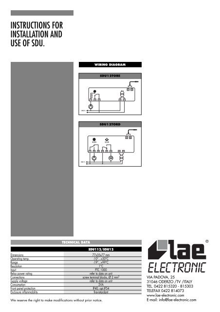
INSTRUCTIONS FORINSTALLATION ANDUSE OF SDU.WIRING DIAGRAMSDU12TORESDU12TORDTECHNICAL DATASDU112/SDU12Dimensions77x35x77 mmOperating temp.-10°...+50°CRange-19°...+99°CResolution 1°CInput PTC 1000Relay power ratingrefer to data on unitConnections screw terminal blocks, Ø 2 mm 2Supply voltagerefer to data on unitConsumption2VAFront panel protectionIP40; opt.IP54Enclusure inflammabilityfire-retardantWe reserve the right to make modifications without prior notice.VIA PADOVA, 2531046 ODERZO /TV /ITALYTEL. 0422 815320 - 815303TELEFAX 0422 814073www.lae-electronic.comE-mail: info@lae-electronic.com
- Page 2 and 3: SDUSDU is a controller allowing tem
INSTRUCTIONS FORINSTALLATION ANDUSE OF SDU.WIRING DIAGRAM<strong>SDU12</strong>TORE<strong>SDU12</strong>TORDTECHNICAL DATASDU112/<strong>SDU12</strong>Dimensions77x35x77 mmOperating temp.-10°...+50°CRange-19°...+99°CResolution 1°CInput PTC 1000Relay power ratingrefer to data on unitConnections screw terminal blocks, Ø 2 mm 2Supply voltagerefer to data on unitConsumption2VAFront panel protectionIP40; opt.IP54Enclusure inflammabilityfire-retardantWe reserve the right to make modifications without prior notice.VIA PADOVA, 2531046 ODERZO /TV /ITALYTEL. 0422 815320 - 815303TELEFAX 0422 814073www.lae-electronic.comE-mail: info@lae-electronic.com
SDUSDU is a controller allowing temperature <strong>and</strong>defrost control of static <strong>and</strong> ventilatedrefrigerators.To get best performance, before installing<strong>and</strong> using it, read this instruction sheetcarefully.1 INSTALLATION1a The instrument is secured to the panelfrom the rear, after making a 29x71 mmhole, by means of the suitable brackets,exerting correct strength. If using the rubbergasket (“S” version), this must be interposedbetween the panel <strong>and</strong> the instrument bezel,checking the perfect adhesion carefully.1b For proper functioning the instrumentneeds an ambient temperature between-10°...+50°C <strong>and</strong> 15%...80% relativeHumidity. To improve protection of the probeagainst electro-magnetic interference, whichmight compromise its function, place its cable<strong>and</strong> the controller away from power lines.1c Probe, power supply <strong>and</strong> outputs must beconnected strictly following the diagram onthe enclosure, where the maximum switchingpowers <strong>and</strong> supply voltage are indicated,too.The probe screen must not be connected toany other leads. If the external transformer isneeded, the instrument must be powered bythe suitable transformer supplied by LAE(mod. TR...).1d Should the instrument be recalibrated,in consequence of probe replacement orconsiderable cable lengthening, then proceedas follows: use an accurate thermometer,make sure that the two probes are at thesame temperature, immersing them in a liquidif necessary. By means of a screwdriver turnthe trimmer located close to the inscription“0°ADJ.”.CAUTION!:• If the relays switch large loads frequently, wesuggest you contact us to obtain information about therelay contact life.• Where delicate or valuable products have to bemaintained in special conditions, we recommend not touse the same instrument for both control <strong>and</strong> limitfunctions.2 FUNCTIONING DESCRIPTIONAfter having installed the instrument <strong>and</strong>carried out the connections, power theinstrument.2a The setpoint, which represents theOn/Off switching temperature of the cooler,is displayed by pushing ; to change itsvalue within the limits programmed in SETUP,while is kept pressed, push to increaseor to decrease. When is released, thenew programmed value is stored.2b In order to start manual defrost, keepkeys <strong>and</strong> pressed for 3 sec.; to stop it,follow the same procedure.2c When the alarm is entered, as a result ofthe temperature staying above the higheralarm threshold or below the lower one forlonger than the delay (see SETUP), theindication "AL" is alternated with the actualtemperature; if the unit is fitted with a buzzer<strong>and</strong>/or alarm relay, this latter is switched on.The alarm condition is stored, therefore thealarm signallings continue regardless of thetemperature. By pressing any of the keys thebuzzer is muted the relay is switched off <strong>and</strong>,if the temperature has returned within thesetpoint limits, the indication "AL" disappears;as long as the alarm condition exists, every30 min. the buzzer/relay is switched On for1 min.During defrost the high alarm is inhibited.2d The On status of the output <strong>and</strong> defrostphase are shown on display through thelighting up of the LED’s placed close to therelative symbols.2e As a result of probe failure, itsconnection breakdown or overrange, "PF" isdisplayed <strong>and</strong> the buzzer/relay is switchedon immediately, which can be muted bypressing any of the pushbuttons. Thecompresseur output will operate according tothe duty cycle programmed in SETUP.2f It’s possible to simulate the behaviour of athermal mass inside the refrigerator; thisallows to avoid rapid fluctuations of thedisplayed temperature, resulting for examplefrom door opening or defrost, but also toreduce hunting due to temperature control.The fluctuation speed of the displayedtemperature depends on the value assigned to“Si”; it’s however possible to display theinstantaneous temperature as long as the keyis kept pressed.3 SETUPSDU configuration is made throughprogramming of the control parameters;access to it is possible through a sequence ofoperations preventing accidental activation.3a Keep keys + + pressed for 3 sec.,exactly in this sequence.To select the desired parameter press key .To show its value press <strong>and</strong> if necessarychange it via or ; store it with . Nokey activation within 10 sec. causes thecontroller to switch over to the basicfunctioning. It’s also possible to select aspecific parameter <strong>and</strong> change its value byfollowing the diagram attached.3b Parameter description:SL: minimum setpoint limit (-19°...+99°C).Sh: maximum setpoint limit (SL...+99°C).hY: hysteresis which, added to the SetPoint, determines the on switching thresholdof the cooler relay (+01°...+10°K). When youhave to maintain a very small hysteresis hY,we recommend to program a suitable valuefor Pc to ensure a long life to relay/contactor<strong>and</strong> compressor.Pc: it represents the minimum Off time ofthe output. It’s the minimum time between Off<strong>and</strong> On switching of the cooler regardless ofthe temperature measured by the probe(00...10 minutes).Po: it allows to programme an offset betweenthe measured <strong>and</strong> the displayed temperature(-19°...+19°K).PF: in case of probe failure, defrosts aresuspended <strong>and</strong> the cooler run is notcontrolled by setpoint but it is determined byPF which represents the duty cycle(00...10*10%), that is the On time <strong>and</strong> theOff time within a 10 min. cycle. For ex.: 06=6 min. On, 4 min. Off. This value should becalculated keeping into consideration thenormal cooler duty cycle. This function allowsto avoid damage to the goods when theactual temperature can not be measured as aresult of a probe failure. The minimumintervention time, during which the operatorcan not interrupt the cycle, has 10 min.duration.dt: the interval between a defrost <strong>and</strong> thenext (01...24 hours); defrost duration is notincluded. In case of a power failure, whenthe power comes on again, the defrost timerre-starts the counting from the point where itwas interrupted, with ±30 min.approximation.dd: defrost duration, i.e. the cooler off cycle(01...99 minutes).do: if set at 01, it allows defrostoptimisation, by considering as defrostscooler pauses of duration equal or greaterthan dd. For ex. dd= 20 min. If the coolerremains off for 20 min. without interruption,the timer will be reset <strong>and</strong> as a consequencethe start of the next defrost will be postponed.If do= 00, optimisation is excluded.dF: it allows to select the display indicationduring defrost. If dF=00, then thetemperature measured by the probe continuesto be displayed; if -1, the display shows "dF"until the setpoint is reached again. IfdF=01...99 min., "dF" is displayed allthrough defrost <strong>and</strong> after until the timeprogrammed has elapsed, unless the setpointis achieved before.AL: lower alarm threshold (-19°C...SL).Ah: higher alarm threshold (Sh...+99°C).Ad: it allows to: exclude the alarm function(-1); programme a delay between thedetection of the alarm condition <strong>and</strong> itssignalling (00...99 minutes).Si: by programming a value between 01 <strong>and</strong>99 you establish the thermal mass to besimulated, if 00 is selected the instantaneousprobe temperature is displayed; the greaterthe programmed value, the greater theresulting display slow down will be. It isimportant to note that temperature <strong>and</strong> alarmcontrol are based on the instantaneous airtemperature <strong>and</strong> are therefore notinfluenced by “Si” values.YY: 01 DO NOT CHANGE. In case thevalue 00 is selected by mistake, after exitfrom the SETUP it’s not possible to haveaccess to it again by following the sequencedescribed at point 3a.Act as follows: switch off the unit; while thethree pushbuttons are kept pressed, turn onthe unit again.WARRANTYLAE electronic Srl warrant that their products are free ofany defects in workmanship <strong>and</strong> materials for a period of 1(one) year from date of production shown on the enclosure.LAE electronic Srl shall only repair or replace thoseproducts of which defects are due to LAE electronic Srl <strong>and</strong>recognised by their technicians. LAE electronic Srl are notliable for damages resulting from malfunctions of theproducts.Defects due to exceptional operating conditions,misapplication <strong>and</strong>/or tampering will void the warranty.All transport charges for returning the product to themanufacturer, after prior authorisation by LAE electronicSrl, <strong>and</strong> for the return to the purchaser are always for theaccount of the purchaser.
SDUSLSh-19...99SL...99°C°CSetpoint minimoMinimum setpointP.d.C. minimumMinimaler SollwertMínimo Punto de AjusteSetpoint massimoMaximum setpointP.d.C. maximumMaximaler SollwertMáximo Punto de AjustehY01...10°KIsteresi termostatoThermostat hysteresisHystérésis thermostatThermostat- SchalthystereseHistéresis termostatoPc00...10min.Tempo min. pausa compressoreRelay min. Off timeArrêt minimum compresseurMin. Kompressor- AuszeitTiempo mín. parada compresorPo-19...19°KCorrezione sondaProbe OffsetCompensation de la SondeFühler-AbgleichungCorrección SondaPF00...10%Ciclo lavoro/pausa con sonda difettosaDuty cycle with probe failureCycle travail/pause avec sonde défectueuseLauf/Pause-Zyklus bei FühlerfehlerCiclo de trabajo/pausa con fallo sondadt01...24HrsIntervallo fra sbrinamentiInterval between defrostsIntervalle entre dégivragesIntervall zwischen AbtauungenIntervalo entre desescarchesdd01...99min.Durata sbrinamentoDefrost durationDurée dégivrageAbtaudauerDuración desescarchedo00...01flagOttimizzazione sbrinamentoDefrost optimisationOptimisation dégivrageAbtauoptimierungOptimizacion desescarchedF-1...99flagControllo display in sbrinamentoDisplay control during defrostContrôle affichage en dégivrageAnzeigekontrolle bei AbtauungControl display en desescarcheAL-19...SL°CSoglia inferiore allarmeLower alarm thresholdSeuil inférieur d'alarmeUntere AlarmschwelleUmbral inferior de alarmaAhSh...99°CSoglia superiore allarmeHigher alarm thresholdSeuil supérieur d'alarmeObere AlarmschwelleUmbral superior de alarmaAd-1...99Si 00...99YY01flagflagNON MODIFICAREDO NOT CHANGENE PAS CHANGERNICHT ÄNDERNNO MODIFICARRitardo allarmeAlarm delayRétard d'alarmeAlarmverzögerungRetraso de alarmaSimulazione massa termicaThermal mass simulationSimulation de masse thermiqueThermische Masse- SimulierungSimulación masa térmica


