

Ceramic Surface Mount MLC Capacitors - AVX
Ceramic Surface Mount MLC Capacitors - AVX
Ceramic Surface Mount MLC Capacitors - AVX
- No tags were found...

You also want an ePaper? Increase the reach of your titles
YUMPU automatically turns print PDFs into web optimized ePapers that Google loves.
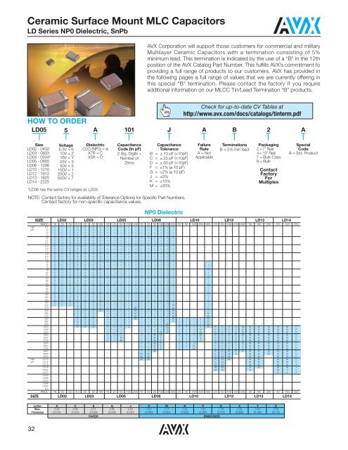
<strong>Ceramic</strong> <strong>Surface</strong> <strong>Mount</strong> <strong>MLC</strong> <strong>Capacitors</strong>LD Series NP0 Dielectric, SnPb<strong>AVX</strong> Corporation will support those customers for commercial and militaryMultilayer <strong>Ceramic</strong> <strong>Capacitors</strong> with a termination consisting of 5%minimum lead. This termination is indicated by the use of a “B” in the 12thposition of the <strong>AVX</strong> Catalog Part Number. This fulfills <strong>AVX</strong>’s commitment toproviding a full range of products to our customers. <strong>AVX</strong> has provided inthe following pages a full range of values that we are currently offering inthis special “B” termination. Please contact the factory if you requireadditional information on our <strong>MLC</strong>C Tin/Lead Termination “B” products.HOW TO ORDERLD055A101JCheck for up-to-date CV Tables athttp://www.avx.com/docs/catalogs/tinterm.pdfAB2ASizeLD02 - 0402LD03 - 0603LD04 - 0504*LD05 - 0805LD06 - 1206LD10 - 1210LD12 - 1812LD13 - 1825LD14 - 2225Voltage6.3V = 610V = Z16V = Y25V = 350V = 5100V = 1200V = 2500V = 7DielectricC0G (NP0) = AX7R = CX5R = D*LD06 has the same CV ranges as LD03.CapacitanceCode (In pF)2 Sig. Digits +Number ofZerosCapacitanceToleranceB = ±.10 pF (
<strong>Ceramic</strong> <strong>Surface</strong> <strong>Mount</strong> <strong>MLC</strong> <strong>Capacitors</strong>LD Series X7R Dielectric, SnPb<strong>AVX</strong> Corporation will support those customers for commercial andmilitary Multilayer <strong>Ceramic</strong> <strong>Capacitors</strong> with a termination consistingof 5% minimum lead. This termination is indicated by the use of a“B” in the 12th position of the <strong>AVX</strong> Catalog Part Number. This fulfills<strong>AVX</strong>’s commitment to providing a full range of products to ourcustomers. <strong>AVX</strong> has provided in the following pages a full range ofvalues that we are currently offering in this special “B” termination.Please contact the factory if you require additional information onour <strong>MLC</strong>C Tin/Lead Termination “B” products.Check for up-to-date CV Tables athttp://www.avx.com/docs/catalogs/tinterm.pdfHOW TO ORDERLD055C101JAB2ASizeLD02 - 0402LD03 - 0603LD04 - 0504*LD05 - 0805LD06 - 1206LD10 - 1210LD12 - 1812LD13 - 1825LD14 - 2225Voltage6.3V = 610V = Z16V = Y25V = 350V = 5100V = 1200V = 2500V = 7DielectricC0G (NP0) = AX7R = CX5R = D*LD06 has the same CV ranges as LD03.CapacitanceCode (In pF)2 Sig. Digits +Number ofZerosCapacitanceToleranceB = ±.10 pF (
<strong>Ceramic</strong> <strong>Surface</strong> <strong>Mount</strong> <strong>MLC</strong> <strong>Capacitors</strong>LD Series X5R Dielectric, SnPb<strong>AVX</strong> Corporation will support those customers for commercial andmilitary Multilayer <strong>Ceramic</strong> <strong>Capacitors</strong> with a termination consistingof 5% minimum lead. This termination is indicated by the use of a“B” in the 12th position of the <strong>AVX</strong> Catalog Part Number. Thisfulfills <strong>AVX</strong>’s commitment to providing a full range of products toour customers. <strong>AVX</strong> has provided in the following pages a fullrange of values that we are currently offering in this special “B”termination. Please contact the factory if you require additionalinformation on our <strong>MLC</strong>C Tin/Lead Termination “B” products.HOW TO ORDERLD05SizeLD02 - 0402LD03 - 0603LD04 - 0504*LD05 - 0805LD06 - 1206LD10 - 1210LD12 - 1812LD13 - 1825LD14 - 22255Voltage6.3V = 610V = Z16V = Y25V = 350V = 5100V = 1200V = 2500V = 7DDielectricC0G (NP0) = AX7R = CX5R = D*LD06 has the same CV ranges as LD03.101CapacitanceCode (In pF)2 Sig. Digits +Number ofZerosJCapacitanceToleranceB = ±.10 pF (
MIL-PRF-55681 ChipsCDR01-CDR06The CDR01 through CDR06 series (MIL-PRF-55681) of highreliability, high frequency capacitors are available in BP and BX,voltage/temperature options. They are offered in 50 and 100Vversions and capacitance tolerance varies with capacitance andvoltage specifications. Failure rates are between “S” = 0.001% and“M” = 1.0%.HOW TO ORDERCDR01BP101BKSMMIL StyleCDR01CDR02CDR03CDR04CDR05CDR06Voltage TemperatureLimitsBP = 0 ± 30 ppm/ºCwithout voltage;0 ± 30 ppm/ºC withrated voltage from-55ºC to +125ºCBX = ±15% without voltage;+15 -25% with ratedvoltage from -55ºC to+125ºCCapacitanceTwo digit figuresfollowed by multiplier(number of zeros tobe added)e.g. 101 = 100pFRatedVoltageA = 50VB = 100VCapacitanceToleranceJ = ±5%K = ±10%M = ±20%TerminationFinishM = Palladium SilverN = Silver Nickel GoldS = Solder-CoatedU = Base Metallization/BarrierMetal/Solder Coated*W = Base Metallization/BarrierMetal/Tinned (Tin orTin/Lead Alloy)FailureRate LevelM = 1.0%P = .1%R = .01%S = .001%NOTE: Contact factory for availability of Termination andTolerance Options for Specific Part Numbers.*Solder shall have a meltingpoint of 200ºC or less.PACKAGINGBulk is standard packaging. Tape and reel per RS481 is available upon request.35
MIL-PRF-55681 ChipsCDR01-CDR06CDR01 thru CDR06 to MIL-PRF-55681Military Rated temperature WVDCType Capacitance Capacitance and voltage-Designation in pF tolerance temperature limits<strong>AVX</strong> Style 0805/CDR01CDR01BP100B--- 10 J,K BP 100CDR01BP120B--- 12 J BP 100CDR01BP150B--- 15 J,K BP 100CDR01BP180B--- 18 J BP 100CDR01BP220B--- 22 J,K BP 100CDR01BP270B--- 27 J BP 100CDR01BP330B--- 33 J,K BP 100CDR01BP390B--- 39 J BP 100CDR01BP470B--- 47 J,K BP 100CDR01BP560B--- 56 J BP 100CDR01BP680B--- 68 J,K BP 100CDR01BP820B--- 82 J BP 100CDR01BP101B--- 100 J,K BP 100CDR01B--121B--- 120 J,K BP,BX 100CDR01B--151B--- 150 J,K BP,BX 100CDR01B--181B--- 180 J,K BP,BX 100CDR01BX221B--- 220 K,M BX 100CDR01BX271B--- 270 K BX 100CDR01BX331B--- 330 K,M BX 100CDR01BX391B--- 390 K BX 100CDR01BX471B--- 470 K,M BX 100CDR01BX561B--- 560 K BX 100CDR01BX681B--- 680 K,M BX 100CDR01BX821B--- 820 K BX 100CDR01BX102B--- 1000 K,M BX 100CDR01BX122B--- 1200 K BX 100CDR01BX152B--- 1500 K,M BX 100CDR01BX182B--- 1800 K BX 100CDR01BX222B--- 2200 K,M BX 100CDR01BX272B--- 2700 K BX 100CDR01BX332B--- 3300 K,M BX 100CDR01BX392A--- 3900 K BX 50CDR01BX472A--- 4700 K,M BX 50<strong>AVX</strong> Style 1805/CDR02CDR02BP221B--- 220 J,K BP 100CDR02BP271B--- 270 J BP 100CDR02BX392B--- 3900 K BX 100CDR02BX472B--- 4700 K,M BX 100CDR02BX562B--- 5600 K BX 100CDR02BX682B--- 6800 K,M BX 100CDR02BX822B--- 8200 K BX 100CDR02BX103B--- 10,000 K,M BX 100CDR02BX123A--- 12,000 K BX 50CDR02BX153A--- 15,000 K,M BX 50CDR02BX183A--- 18,000 K BX 50CDR02BX223A--- 22,000 K,M BX 50Add appropriate failure rateAdd appropriate termination finishCapacitance ToleranceMilitary Rated temperature WVDCType Capacitance Capacitance and voltage-Designation in pF tolerance temperature limits<strong>AVX</strong> Style 1808/CDR03CDR03BP331B--- 330 J,K BP 100CDR03BP391B--- 390 J BP 100CDR03BP471B--- 470 J,K BP 100CDR03BP561B--- 560 J BP 100CDR03BP681B--- 680 J,K BP 100CDR03BP821B-- 820 J BP 100CDR03BP102B--- 1000 J,K BP 100CDR03BX123B-- 12,000 K BX 100CDR03BX153B--- 15,000 K,M BX 100CDR03BX183B--- 18,000 K BX 100CDR03BX223B--- 22,000 K,M BX 100CDR03BX273B--- 27,000 K BX 100CDR03BX333B--- 33,000 K,M BX 100CDR03BX393A--- 39,000 K BX 50CDR03BX473A--- 47,000 K,M BX 50CDR03BX563A--- 56,000 K BX 50CDR03BX683A--- 68,000 K,M BX 50<strong>AVX</strong> Style 1812/CDR04CDR04BP122B--- 1200 J BP 100CDR04BP152B--- 1500 J,K BP 100CDR04BP182B--- 1800 J BP 100CDR04BP222B--- 2200 J,K BP 100CDR04BP272B--- 2700 J BP 100CDR04BP332B--- 3300 J,K BP 100CDR04BX393B--- 39,000 K BX 100CDR04BX473B--- 47,000 K,M BX 100CDR04BX563B--- 56,000 K BX 100CDR04BX823A--- 82,000 K BX 50CDR04BX104A--- 100,000 K,M BX 50CDR04BX124A--- 120,000 K BX 50CDR04BX154A--- 150,000 K,M BX 50CDR04BX184A--- 180,000 K BX 50<strong>AVX</strong> Style 1825/CDR05CDR05BP392B--- 3900 J,K BP 100CDR05BP472B--- 4700 J,K BP 100CDR05BP562B--- 5600 J,K BP 100CDR05BX683B--- 68,000 K,M BX 100CDR05BX823B--- 82,000 K BX 100CDR05BX104B--- 100,000 K,M BX 100CDR05BX124B--- 120,000 K BX 100CDR05BX154B--- 150,000 K,M BX 100CDR05BX224A--- 220,000 K,M BX 50CDR05BX274A--- 270,000 K BX 50CDR05BX334A--- 330,000 K,M BX 50<strong>AVX</strong> Style 2225/CDR06CDR06BP682B--- 6800 J,K BP 100CDR06BP822B--- 8200 J,K BP 100CDR06BP103B--- 10,000 J,K BP 100CDR06BX394A--- 390,000 K BX 50CDR06BX474A--- 470,000 K,M BX 50Add appropriate failure rateAdd appropriate termination finishCapacitance Tolerance36
MIL-PRF-55681 ChipsCDR31-CDR35The CDR31 through CDR35 series (MIL-PRF-55681) of highreliability, high frequency capacitors are available in BP and BX,voltage/temperature options. They have a metric dimension bodysize and are offered in 50 and 100V versions. Capacitancetolerance varies with capacitance and voltage specifications andfailure rates are between “S” = 0.001% and “M” = 1.0%.HOW TO ORDERCDR31BP101BKSMMIL StyleCDR31CDR32CDR33CDR34CDR35Voltage TemperatureLimitsBP = 0 ± 30 ppm/ºCwithout voltage;0 ± 30 ppm/ºC withrated voltage from-55ºC to +125ºCBX = ±15% without voltage;+15 -25% with ratedvoltage from -55ºC to+125ºCNOTE: Contact factory for availability of Termination andTolerance Options for Specific Part Numbers.CapacitanceTwo digit figuresfollowed by multiplier(number of zeros tobe added)e.g. 101 = 100pFRatedVoltageA = 50VB = 100VCapacitanceToleranceC = ±.25 pFD = ±.5 pFF = ±1%J = ±5%K = ±10%M = ±20%TerminationFinishM = Palladium SilverN = Silver Nickel GoldS = Solder-CoatedY = 100% TinU = Base Metallization/BarrierMetal/Solder Coated*W = Base Metallization/BarrierMetal/Tinned (Tin orTin/Lead Alloy)*Solder shall have a meltingpoint of 200ºC or less.FailureRate LevelM = 1.0%P = .1%R = .01%S = .001%PACKAGINGBulk is standard packaging. Tape and reel per RS481 is available upon request.CDR31 thru CDR35 to MIL-PRF-55681Type DielectricCapacitanceVoltagepFToleranceWVDCCDR31 BP 1.0 - 2.4 B,C 100CDR31 BP 2.7 - 9.1 B,C,D 100CDR31 BP 10.0 - 470 F,J,K 100CDR31 BP 510 - 680 F,J,K 50CDR31 BX 470 - 4,700 K,M 100CDR31 BX 5,600 - 18,000 K,M 100CDR32 BP 1.0 - 2.4 B,C 100CDR32 BP 2.7 - 9.1 B,C,D 100CDR32 BP 10.0 - 1,000 F,J,K 100CDR32 BP 1,100 - 2,200 F,J,K 50CDR32 BX 4,700 - 15,000 K,M 100CDR32 BX 18,000 - 39,000 K,M 50CDR33 BP 1,000 - 2,200 F,J,K 100CDR33 BP 2,700 - 3,300 F,J,K 50CDR33 BX 15,000 - 27,000 K,M 100CDR33 BX 39,000 - 100,000 K,M 50CDR34 BP 2,200 - 4,700 F,J,K 100CDR34 BP 5,100 - 10,000 F,J,K 50CDR34 BX 27,000 - 56,000 K,M 100CDR34 BX 100,000 - 180,000 K,M 50CDR35 BP 4,700 - 10,000 F,J,K 100CDR35 BP 11,000 - 22,000 F,J,K 50CDR35 BX 56,000 - 150,000 K,M 100CDR35 BX 180,000 - 470,000 K,M 5037
MIL-PRF-55681 ChipsCDR11-CDR14The CDR11 through CDR14 series (MIL-PRF-55681) of highreliability, high frequency capacitors are available in BG and BP,voltage/temperature options. They are offered in versions from 50to 500V. Case sizes are 0605 for CDR11 & 12 and 1111for CDR13 & 14. Failure rate are between “S” = 0.001% and“M” = 1.0%.HOW TO ORDERCDR12BG101AKUSMIL StyleCDR11CDR12CDR13CDR14PACKAGINGVoltage TemperatureLimitsBG = +90 ± 20 ppm/ºCwith and withoutrated voltage from-55ºC to +125ºCBP = 0 ± 30 ppm/ºCwith and withoutrated voltage from-55ºC to +125ºCCapacitanceEIA CapacitanceCode in pFFirst two digits =significant figures or“R” for decimal placeThird digit = numberof zeros or after “R”significant figures.RatedVoltageA = 50VB = 100VC = 200VD = 300VE = 500VCapacitanceToleranceB = ±.1 pFC = ±.25 pFD = ±.5 pFF = ±1%G = ±2%J = ±5%K = ±10%M = ±20%Termination Finish(Military Designations)CodeM = Palladium Silver(CDR11 & 13 only)N = Silver, Nickel, Gold(CDR11 & 13 only)S = Solder-Coated, Final(CDR12 & 14 only)U = Base Metallization/BarrierMetal/Solder Coated*(CDR12 & 14 only)W = Base Metallization/BarrierMetal/Tinned (Tin orTin/Lead Alloy)(CDR12 & 14 only)Y = 100% TinZ = Base Metallization,Barrier Metal(Tin Lead Alloy with4% Lead Min.)FailureRate LevelM = 1.0%P = .1%R = .01%S = .001%Standard packaging = Waffle Pack (maximum quantity is 80)CDR11 thru CDR14 to MIL-PRF-55681Type DielectricCapacitanceVoltagepFToleranceWVDCCDR11/12 BG,BP 0.1 - 0.2 B 50CDR11/12 BG,BP 0.3 - 0.4 B,C 50CDR11/12 BG,BP 0.5 - 6.2 B,C,D 50CDR11/12 BG,BP 6.8 - 9.1 B,C,J,K,M 50CDR11/12 BG,BP 10 - 100 F,G,J,K,M 50CDR11/12 BP 110 - 1,000 F,G,J,K,M 50CDR13/14 BG,BP 0.1 - 0.2 B 200/500CDR13/14 BG,BP 0.3 - 0.4 B,C 200/500CDR13/14 BG,BP 0.5 - 6.2 B,C,D 200/500CDR13/14 BG,BP 6.8 - 9.1 B,C,J,K,M 200/500CDR13/14 BG,BP 10 - 100 F,G,J,K,M 200/500CDR13/14 BG,BP 110 - 200 F,G,J,K,M 200/300CDR13/14 BG,BP 220 - 470 F,G,J,K,M 200CDR13/14 BG,BP 510 - 620 F,G,J,K,M 100CDR13/14 BG,BP 680 - 1,000 F,G,J,K,M 50CDR13/14 BP 1,100 - 5,100 F,G,J,K,M 5038
Extended Range <strong>Surface</strong> <strong>Mount</strong> <strong>MLC</strong>Cto DSCC DrawingsThese extended range surface mount, multilayer ceramiccapacitors provide options for lower voltages and highercapacitance versions to DSCC drawings. Dielectric options are BP,BR and BX. DSCC 05006 covers 0805 case size and DSCC05007 provides the 1206 case size capability.DSCC 05006 0805 Case SizeType DielectricCapacitanceVoltagepFToleranceWVDCDSCC 05006 BP 0.5 C,D 16/25/50/100/200DSCC 05006 BP 1 - 8.2 C,D 16/25/50/200DSCC 05006 BP 10 - 470 F,G,J 16/25/50/200DSCC 05006 BP 560 - 680 F,G,J 16/25/100/200DSCC 05006 BP 820 - 1,000 F,G,J 16/25/50/100DSCC 05006 BP 1,200 - 3,900 F,G,J 16/25/50DSCC 05006 BP 4,700 - 5,600 F,G,J 16/25DSCC 05006 BP 6,800 - 8,200 F,G,J 16DSCC 05006 BR 330 - 22,000 K,M 10/16/25/50/100/200DSCC 05006 BR 33,000 - 47,000 K,M 10/16/25/50/100DSCC 05006 BR 68,000 - 100,000 K,M 10/16/25/50/100DSCC 05006 BR 150,000 K,M 10/16/25/50DSCC 05006 BR 220,000 K,M 10/16/25DSCC 05006 BR 330,000 - 470,000 K,M 10/16DSCC 05006 BR 680,000 - 1µF K,M 10DSCC 05007 1206 Case SizeType DielectricCapacitanceVoltagepFToleranceWVDCDSCC 05007 BP 0.5 - 8.2 C,D 16/25/50/100/200DSCC 05007 BP 10 - 680 F,G,J 16/25/50/100/200DSCC 05007 BP 820 - 1,000 F,G,J 16/25/50/100DSCC 05007 BP 1,200 - 3,900 F,G,J 16/25/50DSCC 05007 BP 4,700 - 5,600 F,G,J 16/25DSCC 05007 BP 6,800 - 8,200 F,G,J 16DSCC 05007 BR 1,500 - 6,800 K,M 10/16/25/50/100/200DSCC 05007 BR 10,000 K,M 10/16/25/50/100DSCC 05007 BR 15,000 - 33,000 K,M 10/16/25/50DSCC 05007 BR 47,000 K,M 10/16/25DSCC 05007 BR 68,000 K,M 10/16DSCC 05007 BR 100,000 K,M 10/16/25DSCC 05007 BR 150,000 - 220,000 K,M 1039
Additional <strong>Surface</strong> <strong>Mount</strong> <strong>MLC</strong>Cwith DSCC ApprovalsThese additional ranges of surface mount multilayer ceramiccapacitors provide additional capability in 0603 and 0402 casesizes. DSCC 03028 covers 0603 case size BP and BR dielectricand DSCC 03029 is for 0402 case size in BP and BR dielectric.For RF surface mount capacitor versions DSCC 06019 covers0605 case size for BP and BG dielectric. DSCC 06022 is for 1210case size and BP and BG dielectric devices.DSCC 05002 covers RF capacitors in 0603 case size, C0Gdielectric.DSCC 03028 0603 Case SizeTypeDielectricCapacitancepFToleranceVoltageWVDCDSCC 03028 BP 0.5 - 9.1 C,D 6.3/10/16/25/50/100DSCC 03028 BP 10 - 330 F,G,J 6.3/10/16/25/50/100DSCC 03028 BP 390 - 1,000 F,G,J 6.3/10/16/25/50DSCC 03028 BP 1,200 - 1,500 F,G,J 6.3/10/16/25DSCC 03028 BR 100 - 1,000 K,M 6.3/10/16/25/50/100/200DSCC 03028 BR 1,200 - 12,000 K,M 6.3/10/16/25/50/100DSCC 03028 BR 15,000 - 39,000 K,M 6.3/10/16/25/50DSCC 03028 BR 47,000 K,M 6.3/10/16/25DSCC 03028 BR 56,000 - 100,000 K,M 6.3/10/16DSCC 03028 BR 120,000 - 220,000 K,M 6.3/10DSCC 03029 0402 Case SizeTypeDielectricCapacitancepFToleranceVoltageWVDCDSCC 03029 BP 0.5 - 9.1 C,D 6.3/10/16/25/50DSCC 03029 BP 10 - 220 F,G,J 6.3/10/16/25/50DSCC 03029 BP 270 - 330 F,G,J 6.3/10/16DSCC 03029 BR 100 - 3,300 K,M 6.3/10/16/25/50DSCC 03029 BR 3,900 - 4,700 K,M 6.3/10/16/25DSCC 06019 RF Capacitor 0605 Case SizeTypeDielectricCapacitancepFToleranceVoltageWVDCDSCC 06019 BP,BG 0.1 - 0.2 B 50/150DSCC 06019 BP,BG 0.3 - 0.4 B,C 50/150DSCC 06019 BP,BG 0.5 - 6.2 B,C,D 50/150DSCC 06019 BP,BG 6.8 - 9.1 B,C,J,K,M 50/150DSCC 06019 BP,BG 10 - 100 F,G,J,K,M 50/150DSCC 06019 BP,BG 110 - 1,000 F,G,J,K,M 50DSCC 06022 RF Capacitor 1210 Case SizeTypeDielectricCapacitancepFToleranceVoltageWVDCDSCC 06022 BP,BG 0.1 - 0.2 B 200/500DSCC 06022 BP,BG 0.3 - 0.4 B,C 200/500DSCC 06022 BP,BG 0.5 - 6.2 B,C,D 200/500DSCC 06022 BP,BG 6.8 - 9.1 B,C,J,K,M 200/500DSCC 06022 BP,BG 10 - 100 F,G,J,K,M 200/500DSCC 06022 BP,BG 110 - 200 F,G,J,K,M 200/300DSCC 06022 BP,BG 220 - 470 F,G,J,K,M 200DSCC 06022 BP,BG 510 - 620 F,G,J,K,M 100DSCC 06022 BP,BG 680 - 1,000 F,G,J,K,M 50DSCC 06022 BP 1,100 - 5,100 F,G,J,K,M 50DSCC 05002 0603 Case SizeTypeDielectricCapacitancepFToleranceVoltageWVDCDSCC 05002 C0G 0.1 - 0.2 A,B 50/100/200/250DSCC 05002 C0G 0.3 - 1 A,B,C 50/100/200/250DSCC 05002 C0G 1.1 - 6.2 A,B,C,D 50/100/200/250DSCC 05002 C0G 6.8 - 100 B,C,J,K,M 50/100/200/25040
Stacked <strong>Surface</strong> <strong>Mount</strong> <strong>MLC</strong> <strong>Capacitors</strong>SM0 Series<strong>AVX</strong> IS QUALIFIED TO MIL-PRF-49470/1 AND MIL-PRF-49470/2HOW TO ORDERSM017CThe SMPS capacitors are designed for high current, high-power and high-temperatureapplications. These capacitors have very low ESR (Equivalent Series Resistance)and ESL (Equivalent Series Inductance). SMPS Series capacitors offer design andcomponent engineers a proven technology specifically designed for programs requiringhigh reliability performance in harsh environments.MIL-PRF-49470 SMPS Series capacitors are primarily used in input/output filters ofhigh-power and high-voltage power supplies as well as in bus filters and DC snubbersfor high power inverters and other high-current applications. These capacitorsare available with through-hole and surface mount leads. The operating temperatureis -55°C to +125°C.The MIL-PRF-49470 capacitors are preferred over the DSCC drawing 87106 capacitors.MIL-PRF-49470 specification was created to produce a robust replacement forDSCC 87106. MIL-PRF-49470 offers two product levels.Level “B” is the standard reliability. Level “T” is the high reliability suitable for spaceapplication.<strong>AVX</strong> is qualified to supply MIL-PRF-49470/1 parts. These are unencapsulatedceramic dielectric, switch mode power supply capacitors. <strong>AVX</strong> is also qualified tosupply MIL-PRF-49470/2 parts. These are encapsulated ceramic dielectric, switchmode power supply capacitors.<strong>AVX</strong> Styles: SM-1, SM-2, SM-3, SM-4, SM-5, SM-6106MB J 650<strong>AVX</strong> StyleSizeSM0 = UncoatedSM5 = EpoxyCoatedCAPABILITYSizeSeedimensionschartVoltage50V = 5100V = 1200V = 2500V = 7TemperatureCoefficientC0G = AX7R = CCapacitance Code(2 significant digits +no. of zeros)10 pF = 100100 pF = 1011,000 pF = 10222,000 pF = 223220,000 pF = 2241 µF = 10510 µF = 106100 µF = 107Note: <strong>Capacitors</strong> with X7R dielectric are not intended for applications across ACsupply mains or AC line filtering with polarity reversal. Contact plant for recommendations.CapacitanceToleranceC0G: J = ±5%K = ±10%M = ±20%X7R: K = ±10%M = ±20%Z = +80%,-20%Test LevelB = Hi-Rel*TerminationJ = Leadsformed inHeightMax Dimension“A”120 = 0.120"240 = 0.240"360 = 0.360"480 = 0.480"650 = 0.650"* Hi-Rel screening for C0G and X7R only. Screening consists of 100% Group A(B Level), Subgroup 1 per MIL-PRF-49470.X7RX7RCase code Cap range Cap range Tolerances ConfigurationsVoltage Min µF Max µF50 1.2 5.4 10 & 20% J Leads*5100 0.68 3.3 10 & 20% J Leads*200 0.47 1.5 10 & 20% J Leads*500 0.15 0.68 10 & 20% J Leads*50 6.8 15.0 10 & 20% J Leads*4100 3.9 8.2 10 & 20% J Leads*200 1.8 3.9 10 & 20% J Leads*500 0.8 1.8 10 & 20% J Leads*50 18.0 47.0 10 & 20% J Leads*3100 10.0 27.0 10 & 20% J Leads*200 4.7 12.0 10 & 20% J Leads*500 2.5 5.4 10 & 20% J Leads*50 120.0 150.0 10 & 20% J Leads*2100 68.0 82.0 10 & 20% J Leads*200 33.0 39.0 10 & 20% J Leads*500 15.0 18.0 10 & 20% J Leads*50 56.0 100.0 10 & 20% J Leads*1100 33.0 56.0 10 & 20% J Leads*200 15.0 27.0 10 & 20% J Leads*500 6.8 12.0 10 & 20% J Leads*50 180.0 270.0 10 & 20% J Leads*6100 100.0 180.0 10 & 20% J Leads*200 47.0 120.0 10 & 20% J Leads*500 22.0 39.0 10 & 20% J Leads** Other lead options available41


