SELECTION GUIDE FOR MOBILE DEHUMIDIFIERS - Dantherm
SELECTION GUIDE FOR MOBILE DEHUMIDIFIERS - Dantherm
SELECTION GUIDE FOR MOBILE DEHUMIDIFIERS - Dantherm

You also want an ePaper? Increase the reach of your titles
YUMPU automatically turns print PDFs into web optimized ePapers that Google loves.
ContentsPages0. Preface 4 - 5Introducing the three parameters needed to choose a CDT mobile dehumidifier1. Why do we need dehumidification? 6 - 7Reasons why dehumidification is necessary1.1 Obsolete method of heating and ventilation1.2 Dehumidification in a closed room1.3 Advantages of condense drying2. How does a mobile dehumidifier work? 8 - 13The basic functions of a mobile dehumidifier2.1 Temperature and airflow2.1.1 Humidity control2.1.2 Temperature control2.2 Principal functionality of the various components2.3 Automatic hot gas defrosting3. Theoretical principles 14 - 19Introduction to the Mollier hx-diagram. See also fold out page to the right3.1 Using the Mollier diagramThree step-by-step examples to help you learn how to use this unusual diagram4. Calculating the dehumidification load 20 - 36Introducing the key problems and applications of mobile dehumidification4.1 Sources and reasons for excess water content in the air4.1.1 Establishing comfortable indoor climate with calculation example4.1.2 Preservation and protection of goods and materials with calculation example4.1.3 Water works. Maintaining temperature and RH-value to avoid corrosion ofwaterpipes, pumps and other equipment with calculation example4.2 Sources and reasons for excess water content in materials4.2.1 Drying out buildings in connection with construction work with calculation example4.2.2 General guidelines for the drying process4.3 Drying out buildings and materials in connection with water damage4.3.1 Drying out water damage under floors5. The <strong>Dantherm</strong> CDT range 37 - 42Introducing the <strong>Dantherm</strong> CDT range5.1 Sophisticated control5.2 User-friendly design5.3 Energy efficiency5.4 Selecting the right dehumidifierAppendixQuick Reference Guide – Rules of thumb 43 - 44Quick and easy rules of thumb for all the examples in the booklet based onempirical dataNotes 45 - 463Copyright © <strong>Dantherm</strong> 2012
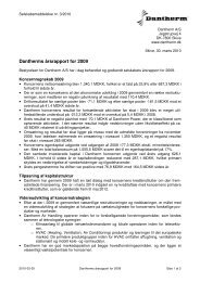
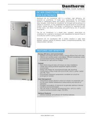
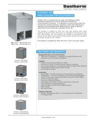
0. PrefaceoC3540% RH 60% RH 80% RH3025201510500 0.20 0.40 0.60 0.80 1.00 1.20 1.40 1,6ol/hourThis second edition of the selection guide for mobile dehumidifiers includes informationabout CDT 30, 30S, 40, 40S, 60 og 90 MKII.In order to choose the right mobile dehumidifier from the <strong>Dantherm</strong> CDT range youneed to know three parameters: the temperature of the air in °C, the required relativehumidity of the air in % RH, and how many litres of water per hour you need to removefrom the air.If you know these parameters it is simply a matter of checking out the capacity curvesof the CDTs (like the one shown above for CDT 30) to find one that is suitable for thejob. You will find the capacity curves for all of the mobile dehumidifiers in the <strong>Dantherm</strong>CDT range in Chapter 5.Whereas temperature and relative humidity are fairly easy to establish, the actualamount of water to be drawn from the air in a given situation is quite another matter.4Copyright © <strong>Dantherm</strong> 2012
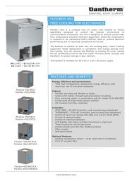
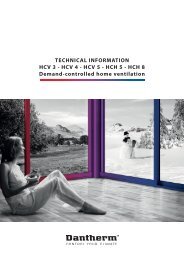
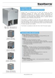
2. How does a mobile dehumidifier work?Condenser (hot)Air flowEvaporator (cold)FanCompressorThermostatic expansion valveThe basic functional principle of a condense drying dehumidifier is really quite simple.A fan draws in humid air and carries it through a refrigerated evaporator. The air iscooled well below its dew point. The water condenses on the cold surface of the evaporatorand drips into a water container or is led directly to a drain. Then the cold dry aircontinues through a hot condenser which heats it up and returns it to the room to pickup new humidity. This procedure is continued until the desired condition is achieved.Example 22.1 Temperature and airflowEvaporatorCondenserTemperature and RH-value1. 25°C 70% RH2. 17°C 88% RH3. 18°C 85% RH mixed air flow4. 33°C 35% RHC % RH+3010029080257013 460201550403020+Air temperatureAir humidityBypassProcess flow8Copyright © <strong>Dantherm</strong> 2012
In the illustrated example on the previous page 25°C hot air with 70% RH (relative humidity)(1) enters the evaporator. Inside the refrigerated evaporator (2) the air temperaturedrops to 17°C and the RH increases to 88%, resulting in condensation and the water isdripping off into a container.To remove all of the water water even with relatively dry air conditions, it is importantthat not all the air is cooled down by the evaporator as there is a risk that the dew pointcannot be fully achieved. Instead only part of the air is led through the evaporator toensure maximum condensation while the rest is by-passed as shown above. This resultsin a mixed 18°C and 85% RH air flow between the evaporator and the condenser (3).When passing the hot condenser the mixed air flow will ensure that the condenser issufficiently cooled.RH%Internal hygrostatThe final result is an outlet air temperature from the dehumidifier of 33°C and 35% RH(4). The temperature is increased because energy is added by the compressor and bythe latent heat from the condensation process.2.1.1 Humidity controlThe internal hygrostat on the display allows control of exactly how much you want tolower the relative humidity. Set the degree of relative humidity required, and the hygrostatwill automatically stop the dehumidification process when the value is met. Thisway you do not risk possible damage from drying out materials too much, and you geta much more energy efficient dehumidification process.Older CDTs do not come with a built-in hygrostat, but an external hygrostat can easilybe connected to all CDTs if needed.External hygrostat2.1.2 Temperature controlIf the room temperature is outside the operating range (3-32°C) the dehumidifier stops.It starts up again automatically when the room temperature is once again within theoperating range.This means that the dehumidifier will keep running as long as the room temperatureremains within the operating range, continuously reducing the RH-value.CDT with external hygrostat9Copyright © <strong>Dantherm</strong> 2012
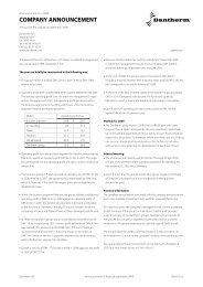
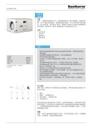
71CDT 30 and 30 S3With capillary tube1: Compressor2: Evaporator3: Condenser4a: Capillary tube5: Liquid line drier6: Solenoid valve7: Fan8: Receiver85 4a2671CDT 40, 40S, 60 and 903With thermostaticexpansion valve1: Compressor2: Evaporator3: Condenser4b: Thermostatic expansion valve5: Liquid line drier6: Solenoid valve7: Fan8: Receiver28564b10Copyright © <strong>Dantherm</strong> 2012
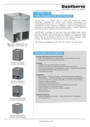
2.3 DefrostingDepending on the room temperature and the RH-value of the air, the evaporator willrun very cold. In general lower air temperature means lower evaporator temperature. Ifthe air temperature is below approximately 15-20°C (depending on the relative humidity)ice will start forming on the surface of the evaporator.If the ice is allowed to accumulate on the evaporator, it will reduce the dehumidificationcapacity of the unit. To prevent this, defrosting is carried out by means of hot gas fromthe compressor.711: Compressor2: Evaporator3: Condenser4a: Capillary tube5: Liquid line drier6: Solenoid valve7: Fan8: Receiver35 4a82612Copyright © <strong>Dantherm</strong> 2012
When the set temperature of 5°C is reached on the surface of the evaporator a timer isactivated and after 30 minutes the solenoid valve (6) opens, and hot gas starts to flushto the evaporator, efficiently melting the ice on the surface. When the set temperature isreached the solenoid valve closes and the system returns to normal active mode again.13Copyright © <strong>Dantherm</strong> 2012
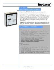
3. Theoretical principlesThe basic functional principles of dehumidification and dehumidifiers are fairly straightforward.The psychrometric calculations involved in the dehumidification process,however, are quite complex. Several interrelating parameters need to be taken intoconsideration.Air density kg/m 31.100Air temperature o C Relative humidity %6055504510%20%30%40%50%4060%1.150353070%80%90%100%90 kJ/kg2580 kJ/kg1.2002070 kJ/kg60 kJ/kg1.2501510520 kJ/kg30 kJ/kg40 kJ/kg50 kJ/kgEnthalpy (h) at saturation4035301.3001.3500-5-10-1510 kJ/kg252015105Water vapour pressure (mbar)-2000 5 10 15 20 25Water content (x) in g water/kg air14Copyright © <strong>Dantherm</strong> 2012
The Mollier hx-diagram is a graphical representation of the interrelation of the temperatureand the relative humidity of the air. This diagram is the key to determing the variousparameters required to calculate the dehumidification load required under any givencircumstance.This is an introduction to help you understand how this basic tool works. In Chapter 4 youwill find a number of examples of how to calculate specific dehumidification loads referingto the Mollier hx-diagram and using the terms and quantities found in the diagram.The Mollier hx-diagram quantitiesTable 1Air density (ρ)The vertical orange axis to the extreme left. Read the airdensity by following the slanting orange lines in the diagram.Air density is the specific gravity measured in kg/m 3 .Air temperature (t)The vertical pink axis to the left with correspondingslightly slanting horizontal gridlines.Temperature is measured in °C.Enthalpy (h)The purple diagonal lines. The enthalpy is the heatenergy content of the air measured in kJ/kg air.Starting at 0°C = 0 kJ/kg.Relative humidity (RH)The green curved lines. The relative humidity is theproportion of actual water vapour pressure in the airexpressed as a percentage (%) of the water vapour pressureat saturation.Water content (x)The horizontal light blue axis at the bottom.The actual water content of the air measured in g water/kg air.Water vapour pressure (p)The vertical blue axis to the right. The water vapourpressure measured in mbar is read to determine the partialwater vapour pressure (rarely used when calculating thedehumidification load). - The brown diagonal line inthe bottom half of the diagram is a help line used whendetermining the partial water vapour pressure.Note that the hx-diagram used throughout this booklet applies to an atmospheric pressure of 1.013 mbar.15Copyright © <strong>Dantherm</strong> 2012
3.1 Using the Mollier diagramWhen you first look at the Mollier diagram it might appear rather confusing with all itscurved, diagonal and slanting lines, but it is actually a quite easy and useful tool onceyou get the hang of it. Actually all the data you need is, the easily measured temperatureand the relative humidity of the air inside the room.Example 3Let us start with a simple example:Air densitykg/m 31.150Air temperature o C40353020%30%40%50%Relativehumidity %60%70%80%90%100%2580 kJ/kg90 kJ/kg1.2002070 kJ/kg60 kJ/kg1.2501510520 kJ/kg30 kJ/kg40 kJ/kg50 kJ/kgEnthalpy (h) at saturation4035301.3001.3500-5-10-1510 kJ/kg252015105Water vapour pressure (mbar)-2000 5 10 15 20 25Water content (x) in g water/kg airWe want to calculate the enthalpy or heat energy needed to raise the temperature in agiven room with a relative humidity of 60% RH from 20°C to 30°C.Start off by finding the 20°C point on the pink axis to the left. Now follow the slightlyupward slanting horizontal gridline to the point where it crosses the 60% RH greencurved line. If you follow the purple diagonal line to the point where it crosses the green100% RH line you will see that h=42 kJ/kg.16Copyright © <strong>Dantherm</strong> 2012
Now go back to the point indicating 20°C/60% RH. Raise the temperature verticallyuntil you cross the 30°C gridline. You will notice that the relative humidity drops toabout 35% in the process. But as we are interested in the enthalpy needed to raise thetemperature to this point you should again follow the purple diagonal line to the pointwhere it crosses the green 100% RH line. Now you should get h=52 kJ/kg.The rest is easy: h= (52-42) = 10 kJ/kg air heat energy must be added to the air in theroom in order to raise the temperature from 20°C to 30°C.Now let us have a look at the data found in example 1 on page 6. In this example weestablished that on a hot dry summer’s day in Denmark a drop from 20°C daytime temperatureto 0°C nightime temperature inside a 80 m 3 room would result in almost a half alitre of water being condensed out of the air, and this water would form on cold surfaces.Example 41.200Air temperature o C 50% 60% 70% 80% 90%100% Relative humidity %20kJ/kgAir densitykg/m 31.2501510520 kJ/kg30 kJ/kg40 kJ/kg50 kJ/kg60 kJ/kgEnthalpy (h) at saturation4035301.3001.3500-5-10-1510 kJ/kg252015105Water vapour pressure (mbar)-2000 5 10 15 20 25Water content (x) in g water/kg airThe condensation starts as soon as the temperature reaches the dew point. To establishthe dew point at 20°C and 60% RH find the 20°C point on the pink axis. Follow thegridline to the 60% RH point. Now go down the vertical gridline until it meets the green100% RH line from this point follow the horizontal gridline to the left to read a dewpoint temperature of 12°C on the pink axis. Between this temperature and 0°C the watercontent in the air will condense into water inside the room.17Copyright © <strong>Dantherm</strong> 2012
Now follow the vertical line from the 20°C and 60% RH point all the way down to thehorizontal light blue axis at the bottom to read x=8.5 g water/kg air water content in theair. Do the same reading down from the 0°C and 100% RH which should read x=3.5 gwater/kg air.From these readings you can easily calculate that 5 g water/kg air (8.5-3.5) has condensedand formed into condensation inside the room. In an 80 m 3 room this equals0.48 litre.Please note if you want to show how the conditions of air changes during the dropfrom 20°C to 0°C it becomes a deflected curve as condensation will start at the coldestareas in the room when the average RH-value is about 85% RH.Example 5In Example 2 (page 8) the temperature and airflow through a dehumidifier was describedwith this example.EvaporatorCondenserC % RH+Temperature and RH-value1. 25°C 70% RH2. 17°C 88% RH3. 18°C 85% RH mixed air flow4. 33°C 35% RH302520151100908070605040302023 4+Air temperatureAir humidityBypassProcess flow18Copyright © <strong>Dantherm</strong> 2012
Now if you put this data into a Mollier diagram the 4 points read like this:Air density kg/m 31.100Air temperature o C Relative humidity %6055504510%20%30%40%50%4060%1.1503530470%80%90%100%25190 kJ/kg80 kJ/kg1.2001.250201510520 kJ/kg30 kJ/kg2340 kJ/kg70 kJ/kg60 kJ/kg50 kJ/kgEnthalpy (h) at saturation4035301.3001.3500-5-10-1510 kJ/kg252015105Water vapour pressure (mbar)-2000 5 10 15 20 25Water content (x) in g water/kg airNotice the way the dew point shifts during the process.These examples should give you the basic idea of how the hx-diagram works.In Chapter 4 we will put it to use in a number of examples on how to calculate thedehumidification load under various circumstances.19Copyright © <strong>Dantherm</strong> 2012
4. Calculating the dehumidification loadAfter each example in this chapter we will recommend a mobile dehumidifier from the<strong>Dantherm</strong> CDT range. These recommendations are based on the capacity curves foundin Chapter 5.Humidity problems fall into two main categories. One category relates to problemsmainly concerning excess water content in the air. In this case the application of amobile dehumidifier is often a question of establishing a comfortable indoor climateand/or the preservation of rare documents, books, artifacts and other precious materialsat museums and archives, or the protection of electronics and machinery in offices andfactories, or even the buildings themselves.The second category concerns drying out the water content in different kinds of materials.Typically this is a question of drying out building materials in connection with constructionwork or water damage. Mobile dehumidifiers can also be used as an alternativeto costly stationary dehumidifiers in connection with production drying processes(drying wood, herbs, fur, hides, etc.).It is important to distinguish between these two categories when determining themodel type of mobile dehumidifier that needs to be used. Table 2 gives a summary oftypical problems and where they tend to occur.Table 2 Problem Requirement Typical locationExcess watercontent in the airExcess water contentin the materialsEstablish good indoor climatePreserve and protectgoods and materialsDry out buildingsRepair water damageOffice buildings, domesticproperties, conference roomsMuseums and exhibitions,storage rooms for sensitivegoods, water works, etc.Construction siteSites where there have beenfloods, fires or where pipeshave burst.20Copyright © <strong>Dantherm</strong> 2012
4.1 Excess water content in the airThe humidity of the air affects both people, electronic equipment, machinery and variousmaterials in the room. Table 3 is a list of limit RH-values that indicates when variousnegative effects of excess water content in the air set in. Please note that the valueslisted are merely indicative as there are situations in which even lower RH-values mightcause problems. For instance you should keep the RH-value below 40% when dealingwith large cold surfaces.ActivityRH-valueTable 3Dust mites start to propagate drastically RH 45Corrosion occurs, especially in aggressive RH 45atmospheresHygroscopic materials absorb water and start to RH 45-50deteriorate (wood, paper, textiles, foodstuffs, etc.)Paper starts to thicken RH 55Corrosion becomes more progressive RH 60People start to feel uncomfortable at warmtemperatures RH 65It becomes increasingly difficult for people to RH 70control their sweating at hot temperaturesDry rot and mould fungus start growing RH 70In all cases concerning continously high levels of relative humidity it is advisable to lookinto the actual reasons for the problem – not just cure the effects. Often you will findways to reduce or even eliminate the problem before applying mechanical dehumidification.As demonstrated in the previous chapter, the Mollier-hx chart is an important tool indetermining the desired temperature and RH-value for a room or a building. However,you need to consider several parameters before calculating the required dehumidificationload and choosing the right dehumidifier for the job.21Copyright © <strong>Dantherm</strong> 2012
Meteorological dataFirst you have to get hold of some general meteorological information for your geographicarea. Temperature and RH-values change from region to region and they alsovary quite a lot during the year. Statistics are available for most geograhical areas andcan be obtained locally. (See Table 4 for an example of how much outside conditionsfluctuate during a year in Denmark). To make sure that you always have sufficient loadyou should normally enter the temperature and RH-values as worst case scenario forwater content (July level for Denmark). Notice that even with a high RH-value in a coldwinter month the water content of the air is relatively low, whereas the hot summermonths normally constitutes worst case scenarios with a relatively low RH-value andhigh water content due to the fact that hot air holds more water.Table 4Average temperature (°C)Average humidity (% RH) Water content (g water/kg air)January 0 91 2.1February 0 90 2.0March +2 89 3.0April +6 85 4.5May +11 79 6.5June +15 80 8.7July +17 83 10.0August +16 87 9.5September +13 90 8.3October +8 91 5.5November +4 91 3.7December +2 92 3.022Copyright © <strong>Dantherm</strong> 2012
Size of the roomThe size of the room or the building has an indirect influence as it is the amount ofwater in the air that determines the actual dehumidification load required, however,you should calculate the volume of the room in cubic metres to see how much air it willhold.Air changeThe air change, n, is very important as outside air contributes to both the temperatureand RH-values inside the room. Research has shown that in most cases problems concerningexcess water content in the air are caused by air change problems.You must determine or estimate how many times pr. hour the air of the room ischanged. This ventilation might occur naturally because the room is not completelytight or it might be forced due to mechanical ventilation and by doors or windows beingopened from time to time.The additional water content introduced into the room by the air change measured inkg water/hour is calculated by using this formula:W(ventilation) = ρ * V * n * (x 1-x 2)W = g water/hourρ = air density (kg/m 3 ) = the value commonly used is approximately1.2 kg/m 3 at 15-25°CV = room volume (m 3 )n = air change in the room (hour -1 )x 1= water content in the outside air (worst case) (g water/kg air)x 2= water content in the inside air at the required RH-value (g water/kg air)Other sourcesFinally you have to consider the humidity coming from people, processes, products andother sources.23Copyright © <strong>Dantherm</strong> 2012
Not all sources are applicable to every case, but the general formula is:W(total) = W(people) + W(process) + W(goods) + W(ventilation)W(people): Water content contributed by people perspiring. (See Table 5)W(process): Water content contributed by activities and processes inside theroom i.e. production, cooking, washing, etc. and by open watersurfaces inside water works, production facilities, etc. This contributioncan vary quite a lot and must be determined in each case.W(goods): Water content contributed by goods and products dryinginside the room. Often you can obtain information about thiscontribution from the supplierW(ventilation): Water content contributed by the air changing allowing outside airto enter the room.A word of cautionIt is normally NOT advisable to increase the room temperature while using a dehumidifier.Even a slight rise in temperature will reduce performance as the dehumidifier has tocool the air down to the dew point before condensation can begin.4.1.1 Establishing a good indoor climateThe key concern when establishing a comfortable indoor climate is to ensure sufficientair change. In general an air change of 0.5 per hour is recommended to providea sufficient supply of fresh air, but in rooms with a large number of people it might benecessary to increase the rate of air change.An equally important factor is the relative humidity in the room. Many people are allergicto dust mites, fungus and mould. These microorganisms thrive in humid air, but theycannot survive in relatively dry air. This is why you should maintain a RH-value below45% in order to ensure a healthy indoor climate.Table 5Level of ActivityPerspiration rate (g water/h for one person)at a room temperature of 20°CLow 45Medium 125High 20024Copyright © <strong>Dantherm</strong> 2012
In general an air change of 0.5 per hour will ensure a low RH-value, but as we havealready seen, it really depends on a number of factors.In the following example, 5 people are living in an ordinary residential room situatedin Denmark. We want to calculate the required dehumidification capacity needed toestablish an indoor climate with 20°C and 45% RH.Example 6The data:Country:DenmarkLocale:Ordinary residential room, averageVolume of the room: 300 m 3Air change: n = 0,5 pr. hour (See Table 6)Air densityρ = 1.2 kg/m 3 (See hx-diagram)Number of people: 5Activity level: Medium = 125 g water/hour/person (See Table 5)Worst case situation: x 1= 10 g water/kg air (See Table 4)Desired condition:t = 20°C and 45% RH > x 2= 6.5 g water/kg air(x 2is found by using the hx-diagram)Air densitykg/m 31.200Air temperature o C 30% 40% 50% 60% 70% Relative humidity %252060 kJ/kg70 kJ/kg80 kJ/kg90 kJ/kg1.2501510520 kJ/kg30 kJ/kg40 kJ/kg50 kJ/kgEnthalpy (h) at saturation4035301.3001.3500-5-10-1510 kJ/kg252015105Water vapour pressure (mbar)-2000 5 10 15 20 25Water content (x) in g water/kg air25Copyright © <strong>Dantherm</strong> 2012
The calculation:W(ventilation) = 1.2 * 300 * 0.5 * (10-6.5) = 630 g water/hourW(people) = 5 * 125 g = 625 g water/hourW(total) = 630 + 625 = 1,255 g water/hourIn other words we need to remove 1.255 litre of water per hour from the air inside theroom to establish and maintain the desired humidity and temperature.Recommendation: Two CDT 60 units. Capacity: 0.7 litre/hour each unit at 20°C/45% RH.(See capacity curve page 42.)4.1.2 Preserve and protect goods and materialsHumidity problems concerning the preservation and protection of goods and materialsis typically a question of ensuring that the RH-value never exceeds a predeterminedlevel. Usually the locale is a storage room or a warehouse.The quality of storage facilities varies considerably. Often they are either very well sealedoff from the outside air or poorly insulated. In both cases the air change is an importantquantity. In Table 6 you will see the difference in air change in various locales dependingon the quality of the insulation.Table 6However, the air change is not the only parameter to take into account. Again you mustconsider the humidity contribution from people, outside air, goods and possible processesinside the storage room.Room Air change: n (hour -1 )Insulation quality Good Average PoorStorage room 0.2 0.4 0.6Normal residential property 0.3 0.5 0,8Large storage room 0.1 0.3 0.7Example 7In this example we have 100 m 3 of completely dry goods stored in a 500 m 3 large storageroom that is poorly insulated. We want to ensure a temperature of 20°C and that the RH-26Copyright © <strong>Dantherm</strong> 2012
Air densitykg/m 3Air temperature o C 40% 50% 60% 70% Relative humidity %2580 kJ/kg90 kJ/kg1.2002070 kJ/kg60 kJ/kg1.2501510520 kJ/kg30 kJ/kg40 kJ/kg50 kJ/kgEnthalpy (h) at saturation4035301.3001.3500-5-10-1510 kJ/kg252015105Water vapour pressure (mbar)-2000 5 10 15 20 25Water content (x) in g water/kg airvalue stays below 60% RH.The data:Country:DenmarkLocale:Storage room , poorly insulatedVolume of the room: 500 m 3Volume of the stock: 100 m 3Air change: n = 0.6 pr. hour (See Table 6)Air density ρ = 1.2 kg/m 3Worst case situation:x 1= 10 g water/kg air(See Table 4. July: t = 17°C; RH = 83%)Desired condition:t = 20°C and 60% RH > x 2= 8.5 g water/kg air(See hx-diagram)The calculation:W(ventilation) = 1.2*(500-100)*0,6*(10-8.5) = 432 g water/hourW(total) = 0.432 litre water/hour27Copyright © <strong>Dantherm</strong> 2012
Recommendation: CDT 30. Capacity: 0.54 litre/hour at 20°C/60% RH.(See capacity curve page 40).4.1.3 Water worksHumidity conditions at a water works can be quite extreme. Here dehumidification is aquestion of protection and preservation of the water pipes, pumps and other equipmentas well as the building itself.If the relative humidity is too high you will get a large amount of condensation on allmetal surfaces. Paint will peel off the water pipes and serious attacks of corrosion will setin. This increases maintenance costs and reduces the lifetime of the installations and thebuilding.The humid environment also accelerates the growth of fungus and mold. Mosquitosthrive in the humid atmosphere and deposit their eggs in the open reservoir making italtogether very difficult to meet the hygienic requriements.In most cases the water temperature is 6-9°C. This means that the surface temperatureof the pipes is roughly the same. To avoid condensation the dew point temperature hasto be lower than the surface temperature of the pipes.Normally you should maintain a temperature inside the water works that is at least 2°Chigher than the water temperature. At the same time you must keep the RH-value at arelatively low level, and to do so you need dehumidification. Usually ventilation is appliedat water works. An air change between 0.1 - 0.3 times per hour is recommended.In general the temperature inside a water works will rarely raise to more than 16-18°Cdue to the cold water pipes and because part of the building is normally underground.This means that a RH-value below 45% will suffice to avoid condensation all year round.Table 7Room temperature °C 10 12 14 16 18 20Max. RH-value , water = 7°C % RH 80 70 61 54 48 4228Copyright © <strong>Dantherm</strong> 2012
The total dehumidification load is determined by:W(total) = W(water reservoir) + W(ventilation)W(water reservoir) = c * A * (x sa- x 1)W = g water/hourc = constant empiric value 6.25 when the air temperature is min. 2°C higher thanthe water temperatureA = water surface area (m 2 )x sa= water content in the saturated air at water temperature(g water/kg air) at 100% RH.x 1= water content in the air at the desired RH-value and temperature(g water/kg air)W(ventilation) =* V * n * (x -x ) (see page 23 for further explanation).1 2In this example we want to determine the dehumidification load needed in a waterworks with an air temperature of 15°C and a desired RH-value 50% RH. The size of thewater works is 300 m 3 , the water surface is 40 m 2 and the water temperature is 8°C.29Copyright © <strong>Dantherm</strong> 2012
The calculation:W (water reservoir)W (ventilation)W (total)= 6.25 * 40 * (7-5) = 500 g water/hour= ρ * V * n * (x 1-x 2) = 1.2 * 300 * 0.3 * (10-5) = 540 g water/hour= 500 + 540 = 1.04 ltr/hourThe dew point temperature at 15°C and 50% RH is approximately 5°C according to thehx-diagram. This means that the surface temperature of the water pipes must drop below5°C before condensation occurs on the pipes. If the temperature is 8°C there will be NOcondensation of water on the pipes as the actual water temperature is higher than thedew point temperature.Air densitykg/m 31.150Air temperature o C353020% 30% 40% 50% 60%Relativehumidity %70%80%90%100%2580 kJ/kg90 kJ/kg1.2002060 kJ/kg70 kJ/kg1.2501510520 kJ/kg30 kJ/kg40 kJ/kg50 kJ/kgEnthalpy (h) at saturation4035301.3001.3500-5-10-1510 kJ/kg252015105Water vapour pressure (mbar)-2000 5 10 15 20 25Water content (x) in g water/kg airRecommendation: Two CDT 60 units. Capacity: 0.6 litre/hour per unit at 15°C/50% RH. Aswe have seen it is extremely important to have full control of the relation between temperatureand RH-value in this type of situation. To do so we recommend that you equipeach CDT 60 unit with a hygrostat set to 55% RH (see Table 7). This will automaticallycontrol that temperature and humidity conditions are always kept at a level ensuringthat condensation is avoided.31Copyright © <strong>Dantherm</strong> 2012
Water content of different building materials (kg/m 3 )Table 8Material At start of Water Desired Water to beproject chemically condition, dehumidifiedbound by 50% RHWood 80 - 40 40Tile, roof 10 - 10 0Brick, wall 80 - 10 70Lightweight concrete 100-200 - 20 80-180Concrete K 15 II 180 42 38 100Concrete K 25 II 180 57 46 77Concrete K 40 II 180 71 51 58Source: Fukthandbok, AB Svensk Byggtjänst, StockholmIn this example we want to calculate the dehumidification load required to dry outexcess water from a newly constructed building in 30 days. The building is 2.4 m high,7 m wide and 16 m long. The walls and ceiling are constructed from pre-dried wood.The floor, however, needs to be dried out as it is made from 10 cm thick concrete, K 40 II.Example 9The data:Period:30 daysDrying condition:t = 20°C and 50% RH (average between startinghumidity at 60% RH and ending at approx. 40% RH)Volume of building: 2.4 * 7 * 16 = 268.8 m 3Materials: Concrete K 40 II, 10 cm (see Table 8)33Copyright © <strong>Dantherm</strong> 2012
The calculation:Concrete volume to be dehumidified:V = 16 * 7 * 0.1 = 11.20 m 3Water content in concrete floor:Q = 11.20 * 58 kg water/m 3 = 649.6 kg waterWe need to remove 649.6 L water in 30 days:W = 649.6/30 = 21.65 L/24 hoursWe need a dehumidification capacity of 21.65 L/24 hours.Recommendation: CDT 40. Capacity: 0.70 litre/hour at 20°C/50% RH. One CDT 40 willremove 16.8 L/24 hours. This means that two CDT 40 units should do the job.Note that the drying process is quickest in the beginning as the water content is veryhigh when you start the process. As the RH-value decreases the overall dehumidificationcapacity will also decrease.4.2.2 Guidelines for the drying processWhen dehumidification is used to dry out buildings and materials the dehumidifierruns continuously. The relative humidity is gradually lowered allowing further evaporationfrom the damp materials in the room. The amount of evaporation depends on thetemperature of the room, the materials and the humidity of the air.One of the advantages of condense drying is that the drying proces is stable andgentle. If time is not of the essence the optimum dehumidification process is achievedby maintaining a stable condition of 20°C and approximately 40% RH in the room. Thisway you maintain a perfect balance between the dry air in the building and humidbuilding materials, avoiding surface drying and cavitation as well as damage to predriedmaterials such as parquet floors.Add heat if necessary, but keep in mind that forcing the drying process might beharmful. There is a risk of surface drying and cavitation, with only surfaces being dried,whereas a lot of humidity remains within cavities inside the wall. This prolongs the dryingperiod as the humidity will not easily penetrate the dry surface. Surface drying alsoinvolves the risk of cracks appearing in the surfaces of walls, ceilings and floors.34Copyright © <strong>Dantherm</strong> 2012
It is important that the room/building is as sealed as possible. Also make sure that thebuilding is well protected against rain and snow. You need to ventilate while paintinginside the building, but remember to seal the locale or building properly when it isempty. Also remember to avoid pre-dried materials absorbing water because of openwindows.If the air change inside the room is not controlled, then changing ambient temperaturesand humidities make the process much more difficult to control. In the winter thecold outside air will normally contain a minimum of water and the humidity is not likelyto increase much even if the air change is considerable. Energy consumption, however,will increase dramatically as you need to heat up the cold incoming air. In the summerthe water content could be quite high and you will have to remove even more waterfrom the building or locale if it is not sealed off adequately.In most cases the humidity is concentrated in cellars and in areas where water is beingused in the construction work going on i.e. painting, concrete mixing, etc. Set up yourdehumidifiers at these positions where they can do most good.4.3 Drying out water damageAs mentioned earlier it is difficult to give exact guidelines for how to approach a waterdamage situation, as both the nature and extent of water damage varies considerably.However, there are some general points that you should always take into consideration.It is essential to contain the damage by sealing off the afflicted area as quickly as possibleto avoid outside air or other sources adding humidity to the locale. This way youonly have to deal with the water that is already in the locale.It is equally important to remove the moisture as quickly as possible. In most cases it isbeneficial to add heat to the room to increase the evaporation. This is especially true if thewater damage occurred recently and the water has not had time to penetrate deep intofurniture and moveables, or walls, floors and other parts of the building structure.If the water has had time to penetrate deep into the building structure you need to usea larger dehumidification capacity to get quick results.Empirical values are essential to ascertain the required dehumidification load.Please see the rules of thumb in the appendix.35Copyright © <strong>Dantherm</strong> 2012
4.3.1 Water damage under floorsIn the case of underfloor water damage, it is often necessary to tear up the flooringto replace the wet insulation. This is time consuming work and often it is both veryinconvenient and costly as it renders the room virtually useless for as long as the repairwork goes on.In quite a lot of instances, however, a dehumidifier equipped to add heat to the processsuch as the CDT 30 S and CDT 40 S will spare you the inconvenience of breaking up allthe flooring and save a lot of money.Drying out waterdamage under thefloorHot dry air is fed underneath the floor at one end by means of ducts from the dehumidifiers1 kW heater. To ensure sufficient air supply the length of the ducts shouldnot exceed 5 metres. The hot air continuously feeds through a hole at the other end,evaporating water from the insulation and taking up moisture as it passes under thefloor. This allows you to use the room above the afflicted floor while the insulation isbeing dried out.The theoretical calculation involved is extremely difficult. We advise you to use empiricalvalues and rules of thumb found in the appendix.36Copyright © <strong>Dantherm</strong> 2012
5. The <strong>Dantherm</strong> CDT rangeIn the previous chapters we have covered the principles of dehumidification. We havealso established the theoretical background needed to calculate the required dehumidificationload for any given situation.CDT displayIn this chapter we would like to present you with the features and advantages of the<strong>Dantherm</strong> CDT range as well as the specifications and diagrams needed to select theright dehumidifier for the job.5.1 Sophisticated controlOur range of mobile CDTs are high-performance dehumidifiers designed for user-friendlycontrol, handling and transport.The digital finger touch control display is conveniently placed on top of the dehumidifier.Offering easy accessible settings and clearly visible read out during and afteroperation. (Please note that older versions of <strong>Dantherm</strong> CDTs do not feature digitaldisplay and control, instead they are equipped with a run meter and indicator lamps foroperation, full water container and failure alert.)On the display you get exact read out of room temperature, relative humidity, totalrunning hours and total energy consumption. Total hours and kWh are backed up by abattery so they can be easily displayed even when the power is switched off.37Copyright © <strong>Dantherm</strong> 2012
You can also take easy control of the built-in hygrostat to set the RH% the dehumidifieris aiming for.Finally the control panel lets you set a service interval for the CDT unit. When it is timethe display will read “SERVICE” to alert you to keep your CDTs in perfect working order.The digital control also offers self-diagnosis and faultfinding features to identify themost common sources of malfunctioning.300 cm5.2 User-friendly designSpecial care has been put into the design features facilitating handling and transportation.A mobile dehumidifier should be sturdy enough to withstand a reasonably roughtimer on the road, as it is hauled in and out of vehicles. The heavy-duty protective coverand robust construction of the CDT product range ensures a long lifetime of hard work.Positioning of the CDT is important. You should always allow a space of at least 60 cmbetween the intake and the wall and no less than 300 cm for the outlet. Never place theunit near a heat source.Positioning of the CDT60 cmTo ensure optimal positioning in all situations all CDTs are equipped with large rubberwheels and (except CDT 90) adjustable handles. You will be surprised how easy and safethe CDT is to move about even up and down stairs and across seemingly impassableareas.Low weight and optimum weight distribution make handling and transport even easier.Furthermore the CDTs are designed to be stacked so they take up as little space as possibleduring transportation and storage.During operation you will appreciate both the low noise level and how easy the waterreservoir is to use.5.3 Energy efficiencyThe capacity of a mobile dehumidifier is obviously your main concern, but energy consumptionis almost equally important. Special care has been taken to make every CDTunit as energy efficient as possible to reduce over all cost of dehumidification.To give you a quick overview table 9 lists the specific energy consumption for the CDTrange at different temperature and RH-values. SEC = actual power consumption/capacityin litres/hour measured as kWh/l. However, in every day use the digital display onthe unit will give you an exact read out of the actual accumulated kWh used for yourdehumidification tasks.kW kWhSEC = ____ = ____l/h l38Copyright © <strong>Dantherm</strong> 2012
Working range, temperatureWorking range, humidityAir volumeCondense capacity, 20 °C& 60% RHCondense capacity, 30 °C& 80% RHSpecific energy consumptionSEC, 20 °C & 60% RHSpecific energy consumptionSEC, 30 °C & 80% RHPower supplyPower consumption,20 °C & 60% RHNoise level – 1 m from the unitWater tank capacityWeightModel °C % RH m 3 /hL water/24hL water/24h kWh/L kWh/L V/50 HzW dB(A) L KgCDT 30 3-32 40-100 250 13 30 0.85 0.47 230 461 56 7 32CDT 30 S 3-32 40-100350/300*13 30 0.86 0.43 230 456 60 7 34CDT 40 3-32 40-100 350 22 39 0.66 0.50 230 614 59 14 43CDT 40 S 3-32 40-100560/460*19 42 0.83 0.47 230 664 62 14 46CDT 60 3-32 40-100 725 29 62 0.67 0.43 230 800 62 14 47CDT 90 3-32 40-100 1000 41 94 0.71 0.42 230 1214 62 - 62* first figure is free exhaust, second figure is with 5 m hose.Table 9When considering the total energy consumption involved in using a dehumidifier you should alsotake into account the considerable amount of heat emitted from the condenser during the process.This in itself saves you energy, as you don’t have to supply that heat from other energy sources.Let us take for instance a CDT 30 running at 20°C and 60% RH. According to Table 9 a powerconsumption of 461W goes into dehumidifying 0.54 litre/hour (see capacity curve, page 40). That461W of energy is transformed into heat and warms the surroundings.The heat energy resulting from condensing 1 litre of water from the air at 20°C is approx. 680Wh,thus the heat of evaporation from a CDT 30 amounts to 680 * 0.54 = 367W.In total this means that the dehumidifier supplies 461 + 367 = 828W heat to the room. This heat contributionis the reason for the rise in air temperature after the air has passed through the dehumidifier.Example 2 on page 8 shows an increase of 8°C in the air temperature as a result of the dehumidificationprocess.For in depth technical specifications and optional accessories please consult the data sheets for theindividual units in the CDT range, available from <strong>Dantherm</strong> Air Handling.39Copyright © <strong>Dantherm</strong> 2012
5.4 Selecting the right dehumidifierThe capacity diagrams in this chapter are the key to selecting the right dehumidifierfor a specific task. You should always choose a dehumidifier with a capacity equal to orslightly higher than the calculated dehumidification load.There is a diagram for each unit in the CDT range. The three curves in the diagram showthe capacity at 40, 60 and 80% RH respectively. Values for 50 and 70% RH, etc. are foundCDT 30by interpolating between the curves.oC3540% RH 60% RH 80% RH3025201510500 0.20 0.40 0.60 0.80 1.00 1.20 1.40L/hourCDT 30 SoC3540% RH 60% RH 80% RH3025201510500 0.20 0.40 0.60 0.80 1.00 1.20 1.40 1.60L/hour40Copyright © <strong>Dantherm</strong> 2012
CDT 40o C3540% RH 60% RH 80% RH3025201510500 0.20 0.40 0.60 0.80 1.00 1.20 1.40 1.60L/hourCDT 40 SoC3540% RH 60% RH 80% RH3025201510500 0.20 0.40 0.60 0.80 1.00 1.20 1.40 1.60 1.80L/hour41Copyright © <strong>Dantherm</strong> 2012
CDT 60oC3540% RH 60% RH 80% RH3025201510500 0.50 1.00 1.50 2.00 2.50L/hourCDT 90o C3540% RH 60% RH 80% RH3025201510500 0.50 1.00 1.50 2.00 2.50 3.00 3.50 4.00L/hour42Copyright © <strong>Dantherm</strong> 2012
AppendixQuick Reference Guide – Easy rules of thumb formulasIn many cases it is not strictly necessary to perform all the extensive calculations describedin this booklet. Experience allows you to use some shortcuts when selecting a mobiledehumidifier. This empirical data is presented in the table below with easy rules of thumbformulas referring to the problems solved in the examples given in the booklet.W refers to the amount of water drawn from the air in g/hour.V refers to the volume of the room in m 3 .Problem Requirement Typical Assumed Rules of thumblocationair change rateEstablish good Office buildings, 0.5 pr. hour W = V * 2.0 (g/hour)indoor climate domestic houses,conference rooms, etc.Excess watercontent in the airPreserve and Museums and 0.3 pr. hour W = V * 1.2 (g/hour)protect goods exhibitions storageand materialsrooms for sensitivegoods, water works,etc.Excess watercontent in thematerialsRepair water Floods, fires, As low as W = V * 4.0 (g/hour)damage * burst water pipes, possibleetc.* Based on a drying period of 8-12 daysPlease note that concerning drying out a newly constructed building it all comes down to the specific building materials used for walls, floors and roofs. Thewater content of various building materials differ so much that a simple rule of thumb would not make sense. Please refer to Table 8 and Example 9, page 33.1. Establishing a comfortable indoor climateIf the desired RH-value is to be approx. 50% RH use this formula:W = V * 2.0(g/hour)Example: V = 500m 3 > W = 2.0 * 500 = 1,000 g/hour.Recommendation: Two CDT 40 units. Capacity: 0.65 litre/hour at 20°C/50% RH.2. Preserve and protect goods and materialsIf the desired RH-value is to be approx. 50% RH use this formula:W = V * 1.2(g/hour)Example: V = 450 m 3 > W = 1.2 * 450 = 540 g/hourRecommendation: CDT 40. Capacity: 0.65 litre/hour at 20°C/50% RH43Copyright © <strong>Dantherm</strong> 2012
3. Repair water damageAssuming a drying process of 8-12 days and an average condition of t = 20°C/50% RH(starting at 60% RH ending at 40% RH) use this formula:W = V * 4.0(g/hour)Example: V = 280 m 3 > W = 4 * 280 = 1,120 g/hourRecommendation: Two CDT 40 S units. Capacity pr. unit: 0.60 litre/hour at 20°C/50%RH. We recommend that you use S-models with extra air volume and built-in 1kW heatersto force the evaporation and speed up the dehumidification process when dealingwith water damage.Room volume (V) CDT 30 (S) CDT 40 (S) CDT 60 CDT 90< 200 m 3 2 units 1 unit 1 unit 1 unit200 - 300 m 3 3 units 2 units 2 units 1 unit300 - 500 m 3 5 units 3 units 3 units 2 units500 - 750 m 3 7 units 4 units 3 units 2 units44Copyright © <strong>Dantherm</strong> 2012
Notes45Copyright © <strong>Dantherm</strong> 2012
Notes46Copyright © <strong>Dantherm</strong> 2012
Mollier hx-diagramAir density kg/m 31.100Air temperature o C Relative humidity %6055504510%20%30%40%50%4060%1.150353070%80%90%100%90 kJ/kg2580 kJ/kg1.2002070 kJ/kg60 kJ/kg1.2501510520 kJ/kg30 kJ/kg40 kJ/kg50 kJ/kgEnthalpy (h) at saturation4035301.3001.3500-5-10-1510 kJ/kg252015105Water vapour pressure (mbar)-2000 5 10 15 20 25Water content (x) in g water/kg airThe Mollier hx-diagram quantitiesAir density (ρ)Air temperature (t)Enthalpy (h)Relative humidity (RH)Water content (x)Water vapour pressure (p)The vertical orange axis to the extreme left.Air density is the specific gravity measured in kg/m 3 .The vertical pink axis to the left. Temperature is measured in °C.The purple diagonal lines. Enthalpy is the heat contentof the air measured in kJ/kg air. Starting at 0°C = 0 kJ/kg.The green curved lines. The relative humidity is the proportion ofactual water vapour pressure in the air expressed as a percentage (%)of water vapour pressure at saturation.The horizontal light blue axis at the bottom.The actual water content of the air measured in g water/kg air.The vertical blue axis to the right. The water vapour pressuremeasured in mbar is read to determine the partial water vapourpressure (rarely used when calculating the dehumidification load).The brown diagonal line in the bottom half of the diagram is a helpline used when determining the partial water vapour pressure.
DefinitionsAir change n (hour -1 )The air change is measured as the number of times the air inside a room is exchangedby outside air per hour.Air density ρ (kg/m 3 )The specific gravity of the air. The air density decreases as temperature increases. Empiricalvalue commonly used is 1.2 kg/m 3 at 15-25°C.Air temperature (°C)The air temperature corresponds to the average temperature of the room. In certaincases it is advisable to measure the air temperature close to cold surfaces as this iswhere condensation starts.CondensationThe process of water vapour turning into liquid water. This happens at the dew pointtemperature. (See below).DefrostingThe evaporator inside the dehumidifier runs cold enough for ice to form and accumulateon the surface (it is after all the same principle that applies to a refrigerator).Defrosting is the automatic process that removes the ice from the evaporator.Dew point temperatureThe specific temperature at which moisture starts condensing on cold surfaces.Enthalpy h (kJ/kg air)The heat content of the air. Enthalpy is defined as 0 kJ/kg air at 0°C.EvaporatorThe cooling surface inside the dehumidifier. It cools the air well below its dew pointtemperature and drains the water into a container. The name relates to the processgoing on inside the evaporator, where the liquid refrigerant is evaporated into hot gasby the heat taken out of the air.HygrostatOptional accessory that enables the dehumidifier to work only within a set RH-range.Mollier, Richard (1863 – 1935)Professor at Dresden University who pioneered the hx-diagram – a graphical chart ofthe relationship of temperature, pressure, enthalpy, entropy and volume of steam andmoist air, which has has since aided the teaching of thermodynamics to many generationsof engineers.Relative Humiditiy (RH %)Term used to describe the quantity of water vapour in a gaseous mixture of air andwater. Relative humidity is defined as the ratio of the partial pressure of water vapour ina gaseous mixture of air and water to the saturated vapour pressure of water at a giventemperature.Specific Energy Consumption (SEC)SEC = actual power consumption/capacity in litres per hour measured as kWh/L.See page 38.Water content in the air W (g water/kg air)The actual amount of water in the air coming from W(people), W(process), W(goods),W(Ventilation).1 kg water = 1L water
dantherm.comELETRONICS COOLING DEHUMIDIFICATION VENTILATION <strong>MOBILE</strong> HEATING AND COOLING<strong>Dantherm</strong>:With approximately 600 employees worldwide and subsidiaries in Norway, Swedenthe UK, the US and China, <strong>Dantherm</strong> is a market-leading supplier of energy-efficientclimate control solutions for customers across the globe. We operate in thefollowing four main business areas:Electronics cooling:Climate control for electronics and battery cooling in radio base stations and othertelecom infrastructure. Telecom customers include network suppliers and networkoperators.<strong>Dantherm</strong> Air Handling A/SMarienlystvej 65, PO Box 502DK-7800 Skive, DenmarkTel. +45 96 14 37 00Fax +45 96 14 38 20info@dantherm.comDehumidiflcation:Mobile and stationary dehumidifiers for drying buildings and for use in privatepools and wellness centres.Ventilation:Large ventilation systems used in swimming pools and buildings such as shoppingcentres and cinemas requiring frequent air change. The range also includes domesticventilation products based on hign-performance heat exchangers.Mobile heating and cooling:Products for beating or cooling of tents and eguipment used by the armed forcesand aid organisations. The customers are primarily the armed forces in NATO countriesas well as tent and container manufacturers.