Coil-Over - Front End Suspension - Total Cost Involved
Coil-Over - Front End Suspension - Total Cost Involved
Coil-Over - Front End Suspension - Total Cost Involved
- No tags were found...

You also want an ePaper? Increase the reach of your titles
YUMPU automatically turns print PDFs into web optimized ePapers that Google loves.
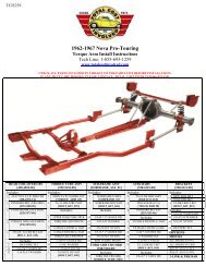
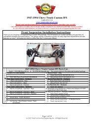
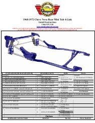
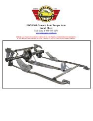
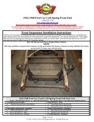
1966 - 1967 Fairlane <strong>Front</strong> <strong>Suspension</strong>Install Sheet1-866-925-1101www.totalcostinvolved.comRead and understand these instructions before starting any work!USE THE PARTS LIST BELOW TO MAKE SURE YOUR KIT IS COMPLETE BEFORE INSTALLATION.IF ANY PIECES ARE MISSING, PLEASE CONTACT: <strong>Total</strong> <strong>Cost</strong> <strong>Involved</strong> Engineering 866-925-11011966 -1967 Fairlane <strong>Front</strong> <strong>Suspension</strong>Installation InstructionsThank you for choosing TCI Engineering’s Fairlane Custom front suspension package. The kit has been designed to not only allowyour vehicle to handle corners, steer and brake better and have more engine compartment room but also have that low sports carstance. Although the install will require some cutting, grinding, drilling, welding and some manual labor, the results are well worth theeffort.Remove all the old suspension components including the steering column.Remove all the old suspension components including the steering column. Iused a die grinder with a cut off wheel to cut the coils in a couple of places formuch easier removal.(c) 2011 <strong>Total</strong> <strong>Cost</strong> <strong>Involved</strong> Engineering, Inc. All Rights Reserved1
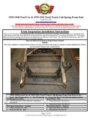
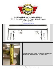
Start with the lower A-arm/motor mount brackets first.When cutting, be careful not to cut into the main frame rail.We will be grinding off the material welded to the main rail.When cutting across the top leave roughly ¼” gap at the fender. This will beground back before the panels go in.Next are the shock towers. The first cut will be made from inside the wheelwell just above the main frame rail flange.The rest of the cutting will be from inside the engine compartment.Cut the lower edges of the tower from the frame rail.(c) 2011 <strong>Total</strong> <strong>Cost</strong> <strong>Involved</strong> Engineering, Inc. All Rights Reserved2
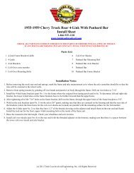
The vertical cuts on the towers are made at the bend radius between the towerand fender panel.Remove the shock tower. You can now grind down the top portion that we leftan extra 1/4”. Grind it back flush to the stock panel being careful not to grindback too far.You will need to install the panels at this point to use them as a template tofinished cutting the lower portion of the factory panel. There are 6 existingholes per side, use the provided 5/16” hardware to hold them in place.Make a mark on the factory panel using the new inner panel as a template.Remove the panel and cut along the line.(c) 2011 <strong>Total</strong> <strong>Cost</strong> <strong>Involved</strong> Engineering, Inc. All Rights Reserved3
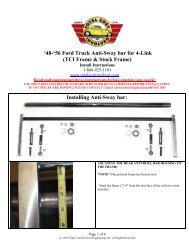
Remove all excess material, welds and paint from the main rails to all for theinstallation of the boxing plates.Remove excess material around shock tower opening until it is flat to thefender panel; also straighten up inside cut lines for clean appearance.If a TCI anti-sway bar package is being installed go ahead and cut off the stocksway bar brackets and the strut rod support channels.This is highly recommended for superior handling and cleaner appearance.There is a split between the top and the side rail that needs to be addressed.The top and outside of the rail need to be seam welded back together.We made a quick little welding guide fixture so we could weld the seam asstraight as possible. We clamped a two foot flat piece of material (I used 1” x2” aluminum bar) about 3/4” down from the top of the frame rail to maintaina straight edge. Then we just laid the welding tip onto the top of the bar andused it as a guide.Massage down any high spots or irregularities that aren’t straight or squarewith a small hammer. Finally, weld the seam and side together making surethe seam attaches both pieces of material.Next grind the welded area flat and square.At this point, you are done removing parts and preparing the frame rails.This is a good point to do any other engine compartment cleaning you wouldlike.(c) 2011 <strong>Total</strong> <strong>Cost</strong> <strong>Involved</strong> Engineering, Inc. All Rights Reserved4
You are now ready to start installing the boxing plates to strengthen the framein the cross member area.The folded inside boxing plates are located by using a bolt and aligning therear holes in the folded bracket with the upper front steering box hole (driversside 7/16” x 3” bolt) and the upper idler arm hole (passenger side 3/8” x 3”bolt).Pull the plate tight up against the frame rail and tack weld the front portion ofthe plate at this time.Once the tack weld is complete you can now install the two rear bolts that holdthe top of the plate down.If the stock sway bar bracket was not removed, you will have to notch theinside flange one inch back for the locating holes to line up.Check to make sure boxing plate sets totally flat all the way around on thestock frame rail.Install the correct outside boxing plate with the bolt and fasten with nut. (Theplate with the hole closest to the rear is the passenger side.)There is a small section of the panel that needs to be removed for the boxingplate to fall into place.Align the boxing plate edge parallel with the top plate exposing an even sectionof the stock frame that when welded will tie both boxing plates to each otherand to the frame.(c) 2011 <strong>Total</strong> <strong>Cost</strong> <strong>Involved</strong> Engineering, Inc. All Rights Reserved5
This is a close up of the parallel edges referenced above with a weld tack forreference.It is critical that the two edges are parallel even if you have to trim off of thebottom edge of the outside boxing plate.This is because the 3/8 inch holes when drilled straight through after weldingserve as a location origin for the cross member locating plate and the A-arm/shock tower (shown on left).After clamping boxing plates using support plates double check to make sureplates are flat on the frame rail and as close to 90 degrees as possible to eachother.It’s time to tack weld inner and outer boxing plates to each other and to theframe. When it comes to welding, I prefer to heli-arc because it’s cleaner andless grinding afterwards but a wire feed will work fine, just a little more cleanupgrinding afterwards.(c) 2011 <strong>Total</strong> <strong>Cost</strong> <strong>Involved</strong> Engineering, Inc. All Rights Reserved6
The rosette welded three slots in the folded boxing plate tie it to the frame.Note; the rosette weld to the left is not done yet.Weld the outside boxing plate totally 360 degrees around tying it to the frameand the inside boxing plate.Weld the inside boxing plate on the top, ends, sides and rosettes.The portion following the bottom line of the frame will be welded later.Lay the formed bottom boxing plate on the bottom of the frame. The leadingedge of the bottom plate will need to sit flush with the leading edge of the sideplates.Use a c-clamp to hold the plate in place and put a couple tack welds on to holdit securely.You’ll notice there is a rounded section that doesn’t match the contour of theframe. The frame will need to be trimmed back to match. This is for clearancebetween the coil-over/shockwave and the frame.Tack-weld the lower boxing plate and double check that everything is square.Weld the inside edge to frame and inside boxing plate tying both together.Weld the boxing plate on the underside of the frame. Don’t weld the outsideedge at this time.(c) 2011 <strong>Total</strong> <strong>Cost</strong> <strong>Involved</strong> Engineering, Inc. All Rights Reserved7
Using the outer edge of the lower boxing plate as the template, grind the twostock frame flanges till they match the profile of the boxing plate edge.Turn the heat up on your welder and seam weld both frame flanges and theboxing plate together.Grind and sand the weld edges, round the corners and spot weld any pits orimperfections for a clean finish..Drill the frame through from both sides in the 3/8” hole in the boxing plates tomake the locating point.Time to make it all look good.Grind and sand the weld edges, round the corners and weld spot fill any pits orimperfections for a clean finish.You are now ready to start installing the cross member and shock towers.First install the one inch wide locating plate using a 3/8 inch bolt and nutthrough the 3/8 inch hole drilled in the boxing plates a few steps ago.Next slide the cross member (steering rack brackets forward) between the railsbehind (firewall side) the locating plates.You may have to trim the ends slightly to get the cross member to tap in. Trimequally from both sides.You want a tight fit so tap the cross member in with a soft mallet.Use a sturdy flat cross bar (approximately 32” long), two short flat spacers(two inch’s) and a long c-clamp to pull the cross member up tight against thebottom of the frame and snug up against the locating plates.(c) 2011 <strong>Total</strong> <strong>Cost</strong> <strong>Involved</strong> Engineering, Inc. All Rights Reserved8
Note:( Please use a large bar and clamp to help finalize task)Next check to make sure that the cross member is 90 degrees to the top of theframe. This is critical for correct engine angle and lower A-arm angle.Corrections can be made by slightly trimming the front or rear edge of thecross member that contacts the bottom of the frame.Double check for square and tack weld all sides and on the bottom.Remove the locating plate and finishing welding all the way around, switchingfrom side to side so as to not build up to much heat. Don’t weld up the inside3/8 inch hole yet as it will be used to locate shock towers.The a-arm/shock tower bracket is mounted with the highest a-arm bolt slotforward and the lowest slot rearward.This is the built in anti-dive feature.Using a 3/8 inch bolt fasten the tower to the frame rail checking to make surebracket sets flat against the boxing plate.(c) 2011 <strong>Total</strong> <strong>Cost</strong> <strong>Involved</strong> Engineering, Inc. All Rights Reserved9
Use a C-clamp from the inside and pull the bracket down snug to the top of theframe rail.When everything is tight, tack weld all the way around then finish weld. Next,remove the tab with the bolt hole in the shock clearance relief and finish weld.Weld up the four 3/8 inch locating holes and finish grind for a cleanappearance.The sway bar bracket is mounted 12 inch’s from the front edge of the crossmember to the center of the bracket.Clamp securely to the bottom of the frame with the wings flush against theinside of the frame and weld.Completely welded.The lower a-arms are installed with the sway bar bung facing forward. The 5/8inch shaft is installed with the acorn nut facing forward with a thin stainlesswasher on both sides of the urethane bushings on the a-arm.(c) 2011 <strong>Total</strong> <strong>Cost</strong> <strong>Involved</strong> Engineering, Inc. All Rights Reserved10
Install the a-arm onto the cross member and install the nylock nut using antiseizeon the threads and tighten.The shock assembly is installed next using the ½ inch bolts.When using Shock Waves with a spherical bearing, a provided spacer will berequired on each side of the spherical bearing.*(3 AN Washer per side; <strong>Total</strong> #6)Install the upper a-arm with the shaft on the inside of the tower, with shaftserrations facing the tower. Install the button head bolts from the outsidethrough the tower then the camber adjustment washers then through the a-arm and install the nylock nut with anti-seize on the threads and position thea-arm bolts in the center of the castor slots for a starting point and tighten thenuts. Note: Start with 4 thick washers per bolt-driver’s side and 2 thickwashers per bolt passenger side, the driver’s side rail is wider than thepassenger side.(c) 2011 <strong>Total</strong> <strong>Cost</strong> <strong>Involved</strong> Engineering, Inc. All Rights Reserved11
Install the rack using the two 5/8” bolts, washers and nylock nuts with antiseizeon the threads and tighten.Clamp a straight edge to each rotor as shown then using a tape measure frontand rear; set the toe-in approximately 1/8” for a starting point.Install the tie rod end jam nut and then the tie rod end turning it an equalamount of turns per side until they line up with the steering arm tapered hole.Check the toe-in again, adjust if needed.Install the sway bar (center drop of bar down) next using the four 3/8” bolts,washers and nylock nuts. The spacer plate goes against the frame bracket firstthen the saddle bracket next.(c) 2011 <strong>Total</strong> <strong>Cost</strong> <strong>Involved</strong> Engineering, Inc. All Rights Reserved13
Before tightening, center bar equally both sides.Install the ½” rod ends as shown with the male end facing up. The sway barrod end link needs to be straight up and down to allow adequate rack andpinion tie rod lock to lock clearance. Adjust by sliding the sway bar for and aftthen tighten bracket bolts.I chose an Ididit brushed steel two inch diameter tilt retro fit steering column(TCI # 326-3100-00) and a Borgenson steering linkage package (TCI # 310-3120-03) to connect the rack and pinion to the steering wheel.The stock dash mount bracket was used with the 2 piece steel reducer thatIdidit furnished. Note: The reducers kept sliding out as I was installing themso I tack welded the top shell to the top bracket and drilled an 1/8 inch hole inthe bottom shell and bracket and pop-riveted the two together.I chose to fabricate a lower column mount that would fit the existing hole &bolt pattern to support the bottom of the column with two set screws on theinside for a simple clean look.(c) 2011 <strong>Total</strong> <strong>Cost</strong> <strong>Involved</strong> Engineering, Inc. All Rights Reserved14
With the column installed, put the Borgenson universal joints onto the end ofthe column and the pinion on the rack. The power rack and the column wereboth ¾”-36 spline X ¾” DD.Correctly measure as shown and cut shaft to length. When in doubt cut a littlelonger and trim to fit. Shaft must never extend past flush with the inside of theyoke this will cause an interference problem and system failure.The rack will have to be unbolted and slid forward to install the shaft.Loctite the set screws before tightening and loctite the jam nuts.(c) 2011 <strong>Total</strong> <strong>Cost</strong> <strong>Involved</strong> Engineering, Inc. All Rights Reserved15
Position the correct panel over the a-arm until the bolt holes line up. The arethree on each side of the panel with the existing stock inner panel holes.Install the 5/16” button head bolts into the existing holes.drill the remaining holes in each side of the panel.Install the remaining bolts and tightenProper ride height is with the lower a-arm level to the ground. Adjust theheight with the threaded ring on the bottom of the coil-over.Caster 4-6 degrees positive with Power steeringCaster 2-4 degrees positive with Manual steeringCamber 0 degreesToe-in 1/8”(c) 2011 <strong>Total</strong> <strong>Cost</strong> <strong>Involved</strong> Engineering, Inc. All Rights Reserved16
If you are using aluminum adjustable shocks adjust the damping knob all theway counter-clockwise (soft) and turn clockwise 3 clicks for a starting point.You are now ready to install the power train.Now you’re finished.Thank you for purchasing a TCI Product if you have any questions please callor visit www.totalcostinvolved.comAll engine installations with this front end will require a fox body rear sumpoil pan small and big block applications. 289-302 Small Block Ford MotorMilodon rear sump pan holds 7 quarts plus the filter, part # 31125.Oil pump pickup #18380 CNC stainless dip stick #22040Canton Racing ProductsOil Pan 352-428 FERoad Race 7 Quart Part#: 15-874 / Oil Pump Pickup # 15-875351 WINDSOR MILODON OIL PANOIL PAN: 31126 / PICK-UP (OIL PUMP): 18385 / OIL PUMP SHAFT:22560 / GASKET: 41004 / WINDAGE TRAY: 32217 / TRAYINSTALLATION KIT: 81167 / DIP STICK: COVER:22030 / PAN: 22040No returns or exchanges without a RMA#.Packages must be inspected upon receipt & be reported within 10 days.If you are missing parts from your kit, TCI Engineering will send the missing parts via FedEx or U.S. mail ground.Returned packages are subject to inspection before replacement/refund is given.(Some items will be subject to a 15%restocking fee)Thank you for your business!(c) 2011 <strong>Total</strong> <strong>Cost</strong> <strong>Involved</strong> Engineering, Inc. All Rights Reserved17