SP600 SERIES WATER METER Operation/ Installation ... - Hobart
SP600 SERIES WATER METER Operation/ Installation ... - Hobart
SP600 SERIES WATER METER Operation/ Installation ... - Hobart

Create successful ePaper yourself
Turn your PDF publications into a flip-book with our unique Google optimized e-Paper software.
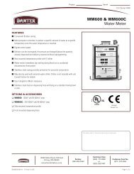
<strong>Operation</strong>/<strong>Installation</strong>Manual<strong>SP600</strong> <strong>SERIES</strong><strong>WATER</strong> <strong>METER</strong>Model Number:Serial Number:Date of <strong>Installation</strong>:_________________________________Baxter • 19220 State Route 162 East • Orting, WA 98360 •Phone: (360) 893-5554 • Toll free: 1-800-280-2495 • Fax: (360) 893-6128FORM 36702 Rev. B (July 2009)
TABLE OF CONTENTSGENERAL ............................................................................................................................................. 3INSTALLATION ..................................................................................................................................... 3Unpacking ........................................................................................................................................ 3Location ........................................................................................................................................... 3Wall Mounting .................................................................................................................................. 3<strong>Installation</strong> Codes and Standards .................................................................................................... 4Electrical Connections ..................................................................................................................... 4Water Supply ................................................................................................................................... 6Drain Connections ........................................................................................................................... 6Plumbing Connections ..................................................................................................................... 7Assembly ......................................................................................................................................... 9Setting Water Pressure .................................................................................................................... 9OPERATION ........................................................................................................................................ 10Environmental Conditions .............................................................................................................. 10Controls ......................................................................................................................................... 10Before First Use ............................................................................................................................. 12Using the <strong>SP600</strong> Water Meter ....................................................................................................... 13Using the Temperature Probe ........................................................................................................ 14Flush Time ..................................................................................................................................... 15Shutdown ....................................................................................................................................... 15CLEANING .......................................................................................................................................... 15MAINTENANCE .................................................................................................................................. 16Service and Parts Information ....................................................................................................... 16Calibration Check .......................................................................................................................... 16TROUBLESHOOTING ........................................................................................................................ 20– 2 –
INSTALLATION, OPERATION AND CARE OFBAXTER MODEL <strong>SP600</strong> <strong>WATER</strong> <strong>METER</strong>SAVE THESE INSTRUCTIONSGENERALThe <strong>SP600</strong> Water Meter is a microcomputer-controlled water delivery system that enables you to accuratelycontrol the water requirements for your baking needs. Through the proper control of water temperatureand volume, the <strong>SP600</strong> will help you gain uniform baking results and maximum productivity.Baxter Water Meters are produced with quality workmanship and material. Proper installation, usage andmaintenance of your water meter will result in many years of satisfactory performance.It is suggested that you thoroughly read this entire manual and carefully follow all of the instructionsprovided.INSTALLATIONThe water meter requires separate hot and cold supply lines. Each line should have a manual shutoff valve(not supplied) at the water meter for servicing and shutdown. Before installing, verify that the electricalservice agrees with the specifi cations on the data plate located on the left panel of the water meter. If thesupply and equipment requirements do not agree, do not proceed with the installation. Contact the BakerySystems service department immediately.UNPACKINGThis water meter was inspected before leaving the factory. The transportation company assumes fullresponsibility for safe delivery upon acceptance of the shipment. Immediately after unpacking, check forpossible shipping damage. If the water meter is found to be damaged, save the packaging material andcontact the carrier within 15 days of delivery.LOCATIONBefore fi nalizing location, make sure that consideration has been given for water supply, draining, electricaloutlets and service clearances.WALL MOUNTINGThe water meter has a detachable base for wall mounting. It is secured by a machine screw located onthe bottom panel.1. With the water meter lying fl at, control face up, remove the machine screw and angle holddown.2. Slide the water meter forward and set aside.3. Position the base on the wall and level left-to-right using a carpenter’s level.– 3 –
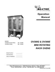
Units with 120VAC Power Supply• Replace any UL listed fast-acting 1A/250VACfuse inside the water meter if fuse is blown.Units with 230VAC/250VAC Power Supply• For 230VAC/250VAC operation, replace anyUL listed fast-acting 3A/600V fuse inside thejunction box if fuse is blown.Input power line and branch circuit protection will beprovided and wired by customer. Refer to Fig. 1 for240V junction box wiring diagram.NOTE: It is recommended that a switch or circuit breaker(marked as the connecting device) is located near theequipment and within easy reach of the operator.Water Chiller OptionIf water chiller is pump-driven, connect the chiller to the water meter as described in the steps below.Connection to the water chiller circuit should be done by a qualifi ed electrician or service technician. Theauxiliary switch is located in the top-mounted junction box.Fig. 1procedures.Disconnect the electrical power to the machine and follow lockout / tagout1. Verify that the water chiller circuit does not exceed theauxiliary relay rating.2. Remove the junction box cover screws, cover andgasket.3. Connect water chiller and meter per Fig. 2.4. Install the junction box gasket and cover. Secure withthe previously removed junction box screws.5. Connect power to the meter. While test is fl owing, verifythat the water chiller pump motor is running in the properdirection.Fig. 2– 5 –
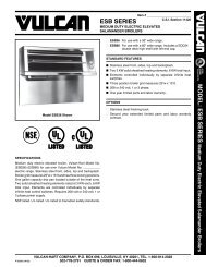
<strong>WATER</strong> SUPPLYThe water meter requires separate hot and cold supply lines. A manual shutoff valve (not supplied) shouldbe installed on each supply line at the water meter to accommodate servicing and shutdown.• HOT <strong>WATER</strong> INLET TEMPERATURE: 140°F (60°C) recommended.• HOT AND COLD <strong>WATER</strong> FLOWING PRESSURE: 30 psi (207 kPa) minimum.• <strong>WATER</strong> HARDNESS: 4 to 6 grains per gallon (0.7 to 1.0 grains per liter) is recommended.DRAIN CONNECTIONS (FIG. 3)The water meter should be located near a sink for the bypass line to drain into while test fl owing or whenwater is adjusting to a set temperature.For water meters equipped with a water chiller and with a water reservoir, a bypass return line should beconnected back to the water chiller reservoir.<strong>WATER</strong> <strong>METER</strong> AND HAND SINK SETUPNOTE: The hot and cold water supply lines can vary in location.Fig. 3– 6 –
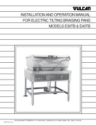
<strong>WATER</strong> <strong>METER</strong> WITH PLUMBING CONNECTIONSNOTE: The Hot and Cold Water Supply lines can vary in location.Fig. 5– 8 –
ASSEMBLYThe water meter is supplied with external fi ttings/components that must be assembled before the watersupply is connected.Qty. FITTING/COMPONENTS Qty. FITTING/COMPONENTS2 Pressure Regulator 2 Dual Check Valve2 90 Degree Elbow 1 Vacuum Breaker1 Dispenser Hose 2 T-Fitting With Pressure Gauge2 Y-Strainer 1 Hand Held Temperature Probe1 20" Bypass Line Hose and Fittings(For water chiller option only. See Fig. 4 under Plumbing Connections.)• Assemble the fi ttings to the water meter as shown in Fig. 5. Use tefl on tape or pipe joint compoundwhen assembling.• The union connection on the water meter has a fl at doughnut gasket. Make sure the gasket is inplace before connecting any fi ttings.• Plug the hand held temperature probe into the end of the fl exible cable attached to the bottompanel of the meter.SETTING <strong>WATER</strong> PRESSUREFor the water meter to operate properly, the water pressure should be set at 30 psi (207 kPa) on eachregulator while it is operating at 125°F (52°C). See <strong>Operation</strong> on the following pages for a description ofthe control panel.1. Press CHANGE UNITS to select English or Metric units. (If the CHANGE UNITS key is locked, seeLocking and Unlocking the Change Units.)2. Press SET TEMP and enter 125°F (52°C) on the numeric key pad. The water temperature value isdisplayed in the <strong>WATER</strong> TEMPERATURE window.3. Hook the dispensing hose over the rim of a sink or drain.4. Press SET AMOUNT and enter 20 lbs 00 oz.5. Press START. The water begins dispensing from the bypass line. The actual water temperature ofthe fl owing water is displayed in the <strong>WATER</strong> TEMPERATURE window.6. Allow the fl owing water temperature to reach 125°F (52°C) and switch over to delivery.7. Adjust both hot and cold water regulators until the pressure gauges read 30 psi (207 kPa).– 9 –
OPERATIONENVIRONMENTAL CONDITIONS• Indoor use at altitudes up to 6,500 ft. (2,000 m).• Main supply voltage fl uctuations up to +/-10% of nominal voltage.• <strong>Installation</strong> category III, pollution degree II.• The normal ambient operating temperature is between 41°F (5°C) and 105°F (40°C). The normaloperating water temperature is between 32°F (0°C) and 125°F (52°C).CONTROLSHand Held Temperature ProbeThe temperature window displays the temperature recorded by the hand held probe. The probe measuresthe temperature of the room, dough or fl our. The temperature range is 32°F to 125°F (0°C to 52°C).Water TemperatureSETTING window - Displays the water temperature as the water meter is dispensing. It also displays theselected water temperature when the meter is idle.FULL COLD light - Indicates the mixing valve is using cold water only.ADJUSTING light - Indicates the mixing valve is adjusting the water temperature.FULL HOT light - Indicates the mixing valve is using hot water only.– 10 –
Water AmountSETTING window - Displays the amount of water to be delivered, in pounds and ounces. Up to fi ve digitsmay be entered; the last two digits are always for ounces.Setting ranges are as follows:Pounds: 0 to 999 Ounces: 0 to 15Liters: 0 to 461 Centiliters: 0 to 99DELIVERED window - Displays the amount of water dispensed in pounds and ounces.BY-PASS light - Indicates the meter is dispensing out of the bypass line.DELIVERING light - Indicates the meter is dispensing the entered water amount out of the dispenserhose.INTERRUPTED light - Indicates the meter has stopped before all of the water amount could bedelivered.COMPLETED/READY light - Indicates the meter has dispensed the entered water amount, and is readyfor the next dispensing cycle.– 11 –
Control PanelFor complete control of the water meter functions, a numeric key pad and the following control keys areprovided.CHANGE UNITS key - Press to change °F to °C and pounds to liters. If CHANGE UNITS key is locked,see Locking and Unlocking the Change Units on page 14.SET TEMP key - Press to enter desired water temperature. Enter the value on the numeric key pad.SET AMOUNT key - Press to enter the amount of water you would like to dispense. Enter the value onthe numeric key pad.START/RESUME key - Press to dispense the entered water amount. Press to resume dispensing cycleafter an interruption.STOP/0 key - Press to stop dispensing water.BEFORE FIRST USEThe water meter should be checked for dispensing accuracy before operation begins. See CalibrationCheck on page 16.– 12 –
USING THE <strong>SP600</strong> <strong>WATER</strong> <strong>METER</strong>Change Units (English/Metric)When the Water Meter is fi rst powered up, press CHANGE UNITS to select the English units (Fahrenheitand Pounds) or Metric unit (Celsius and Liters). If the unit of measure DO NOT change, the CHANGEUNITS key is locked. See Locking and Unlocking the Change Units on page 14 to unlock.1. Press CHANGE UNITS to select Fahrenheit or Celsius.2. Press CHANGE UNITS to select Pounds/Ounces or Liters/Centiliters.The Units can be changed individually as follows:Change Temperature Unit:1. Press SET TEMP.2. Press CHANGE UNITS to select Fahrenheit or Celsius.3. Enter a new temperature setpoint.Change Amount Units:1. Press SET AMOUNT.2. Press CHANGE UNITS to select Pounds or Liters.3. Enter a new amount setpoint.NOTE: Units cannot be changed if the Water Meter is fl owing water to either the bypass or delivery lines,or is paused in this process. The Water Meter automatically saves the unit change on the power down.Setting Water Temperature, Water Amount and Dispensing1. Press SET TEMP.2. Enter desired temperature on the numeric key pad. The water temperature value is displayed in the<strong>WATER</strong> TEMPERATURE window.3. Hook the dispensing hose over the rim of the container to which the water is to be delivered.4. Press SET AMOUNT.5. Enter the desired water amount value on the numeric key pad. The entered value is displayed in the<strong>WATER</strong> AMOUNT SETTING window.NOTE: The value for ounces must be 15 or less; otherwise, the OUNCES display will blink and no waterwill dispense.6. When the water reaches the selected temperature it will automatically switch delivery from the bypassline to the delivery hose.7. Place the dispensing hose on the hook, located on the side of the water meter.NOTE: Do not drain the remaining water from the hose.– 13 –
Operating Hints• To interrupt the water delivery, press STOP/0.• To continue dispensing, press START/RESUME.• To cancel dispensing, press SET AMOUNT.• The amount of water dispensed is displayed in the <strong>WATER</strong> AMOUNT DELIVERED window. Whenthe delivery is complete, the display will blink and indicate 0 POUNDS 0 OUNCES.• If the set temperature is not reached within the preset time allowed (see Flush Time), the meter willfl ash and beep until a new temperature is set, the amount is changed or the START/RESUME buttonis pressed. If the START/RESUME button is pressed, the meter will deliver the set amount.• To get better results, always discard the fi rst water sample when the new temperature is enteredor the unit has not been operated longer than 15 minutes.USING THE TEMPERATURE PROBE1. Verify that the hand held temperature probe is plugged into the end of the fl exible cable attached tothe bottom panel of the meter.2. Place the end of the probe where the temperature needs to be measured. The HAND HELD PROBETEMPERATURE window will display the temperature reading.NOTE: The probe can be used to measure the temperature of the room, dough or fl our in the range of32°F (0°C) to 125°F (52°C). The probe must be in place for 30 seconds to get an accurate temperaturereading.Locking and Unlocking the Change UnitsThe CHANGE UNITS key can be locked to prevent it from being changed. To access Locking and Unlockingthe Change Units parameter, follow the steps below:1. Press SET TEMP.2. Enter 32 using the numeric keypad.3. Press SET AMOUNT.4. Enter 94404 using the numeric keypad. The <strong>WATER</strong> AMOUNT SETTING window displays944 lbs 04 oz.5. Press START/RESUME. The <strong>WATER</strong> TEMPERATURE SETTING window displays 0 (Units is notlocked) or 1 (Units is locked).6. Enter desired value on the numeric keypad. If no change is desired, proceed to the next step.7. Press START/RESUME to save the setting.– 14 –
FLUSH TIMEWater is circulated through the water chiller bypass line to the chiller tank. The fl ush time setting allowsfor a certain amount of time for the meter to fi nd the set temperature, within +/- 2°F (1°C). The defaultfl ush time is 120 seconds.Changing Flush TimeThe fl ush time should be set long enough so the desired set temperature can be reached before switchingfrom the bypass line to the dispensing hose.1. Press SET TEMP.2. Enter 32 using the numeric keypad.3. Press SET AMOUNT.4. Enter 95505 using the numeric keypad. The <strong>WATER</strong> AMOUNT SETTING window displays955 lbs 05 oz.5. Press START/RESUME. The <strong>WATER</strong> TEMPERATURE SETTING window displays the current fl ushtime in seconds.6. Enter a new fl ush time value between 60 and 240 using the numeric key pad.7. Press START/RESUME to save this setting.SHUTDOWNShutdown procedures should be followed when the water meter is not used for an extended period oftime.1. Close the hot and cold water supply valves.2. Empty any remaining water from the dispensing hose.3. Place the dispensing hose on the hook located on the side of the water meter.4. Unplug the power cord from the electrical outlet.CLEANINGprocedures.Disconnect the electrical power to the machine and follow lockout / tagout• Clean the hand held temperature probe daily with warm, soapy water. Follow with a warm waterrinse. Wipe with a soft, dry cloth.• Clean the stainless steel surfaces with a damp cloth and polish with a soft, dry cloth. To removediscolorations, use a nonabrasive cleaner.• Clean the control panel with a damp cloth only.• Do not use any cleaners containing oil or other fl ammable ingredients.• Do not spray the water meter with a hose, pressure washer or steam cleaner.– 15 –
MAINTENANCEprocedures.Disconnect the electrical power to the machine and follow lockout / tagoutOn an annual basis, have the temperature, water volume and water weight settings calibrated by anauthorized Bakery Systems service technician.At regular intervals, check the temperature probe, water volume and weight against a known constant foraccuracy (see Calibration Check below).SERVICE AND PARTS INFORMATIONContact your local authorized Bakery Systems service offi ce.CALIBRATION CHECKBefore performing calibration check:• Check to see if the hot/cold water supply pressure is a minimum of 30 psi (207 kPa).• Check to see if the hot water supply temperature is at least 140°F (60°C).• For the highest degree of accuracy, calibrate the Water Meter in English units.Check Delivery Amount (Three Samples Will Need To Be Collected)NOTE: Wait at least 30 seconds between taking consecutive samples.1. Set water delivery amount to 6 lbs 4 oz which equals 100 ozs.2. Hook the dispensing hose over the rim of a sample container.3. Press START/RESUME to dispense a water sample. Do not drain the remaining water from thedispensing hose between sample collections. If the dispensing hose is dropped or drained, start atstep 2 again.NOTE: The unit will dispense to the overfl ow tube until the temperature set point is reached.4. When the dispensing is complete, place the hose on the hook located on the side of the watermeter.5. Weigh the sample on an accurate (digital type preferred) scale and record the results.6. Repeat steps 2 through 5 to obtain three sample weights.7. Discard the fi rst sample, use the second and third samples for calculation. Both the second andthird samples should be within 1.5 oz (6 lbs 2.5 oz to 6 lbs 5.5 oz) of 100 ozs. If not, then calibratethe delivery.– 16 –
Calibrating Delivery Amount1. Press SET TEMP.2. Enter 32 using the numeric keypad.3. Press SET AMOUNT.4. Enter 93303 using the numeric keypad. The <strong>WATER</strong> AMOUNT SETTING window displays933 lbs 03 oz.5. Press START/RESUME. The <strong>WATER</strong> TEMPERATURE SETTING window displays the currentcalibration value.NOTE: Default setting is 153 and has a range from 150 to 160.6. Adjust calibration value using the table (Fig. 6) below using the numeric keypad.OuncesMeasuredAdjustedCalibrationValue by103.75 103.00 102.25 101.50 100.75 100.00 99.25 98.50 97.75 97.00 96.25-5 -4 -3 -2- 1 0 1 2 3 4 5Fig. 6NOTE: If the sample measurements are not within the range of the chart, call your authorized BakeryServicer.7. Press START/RESUME to store the new calibration value.8. After changing number, go to page 16 to Check Delivery Amount.Changing Time Out For Bypass Flow1. Press SET TEMP.2. Enter 32 using the numeric keypad.3. Press SET AMOUNT.4. Enter 95505 using the numeric keypad. The <strong>WATER</strong> AMOUNT SETTING window displays955 lbs 05 oz.5. Press START/RESUME. The <strong>WATER</strong> TEMPERATURE SETTING window displays the currentcalibration value.6. Enter a new calibration value between 60 and 240 (1 number is 1 second) using the numerickeypad.7. Press START/RESUME to store the new calibration value.NOTE: Determine how long the unit attempts to adjust the water temperature to the water temperaturesetting before beeping and giving the operator an opportunity to manually start the measured fl ow eventhough temperature is not yet at set point. The value ranges between 60 seconds to 240 seconds (1number is 1 second). The default value is 120.– 17 –
Calibrating Delivery Temperature (Low and High Temperature Calibration)Low End Water Calibration 32°F (0°C)1. Press SET TEMP.2. Enter 32 using the numeric keypad.3. Press SET AMOUNT.4. Enter 96606 using the numeric keypad. The <strong>WATER</strong> AMOUNT SETTING window displays966 lbs 06 oz.5. Press START/RESUME. The <strong>WATER</strong> TEMPERATURE SETTING window displays the currentcalibration value.6. Enter a new calibration value between 0 and 30 (1 number is 0.5°F, so 0 = -7.5°F, 15 = 0°F and 30= +7.5°F). The default value is 15 (which is 0 degrees of the temperature offset).7. Press START/RESUME to store the new calibration value.NOTE: To determine what number is needed here, determine the number of degrees by which the deliverywas off and adjust the calibration value up by 2 numbers per degree to decrease the actual temperaturedelivered or down by 2 numbers per degree to increase the actual temperature delivered. See the examplein Fig. 7.High End Water Calibration 120°F (49°C)1. Press SET TEMP.2. Enter 32 using the numeric keypad.3. Press SET AMOUNT.4. Enter 96607 using the numeric keypad. The <strong>WATER</strong> AMOUNTSETTING window displays 966 lbs 07 oz.5. Press START/RESUME. The <strong>WATER</strong> TEMPERATURE SETTINGwindow displays the current calibration value.6. Enter a new calibration value between 0 and 30 (1 number is0.5°F, so 0 = -7.5°F, 15 = 0°F and 30 = +7.5°F). The default valueis 15 (which is 0 degrees of the temperature offset).7. Press START/RESUME to store the new calibration value.NOTE: To determine what number is needed here, determine thenumber of degrees by which the delivery was off and adjust thecalibration value up by 2 numbers per degree to decrease the actualtemperature delivered or down by 2 numbers per degree to increasethe actual temperature delivered. See the example in Fig. 7.Delivered WaterTemperature (F)ChangeNumber92.50 093.00 194.00 395.00 596.00 797.00 998.00 1199.00 13100.00 15101.00 17102.00 19103.00 21104.00 23105.00 25106.00 27107.00 29107.50 30Fig. 7– 18 –
Calibrating Hand Held Probe Temperature (Low and High Temperature Calibration)Low End Probe Calibration 32°F (0°C)1. Press SET TEMP.2. Enter 32 using the numeric keypad.3. Press SET AMOUNT.4. Enter 97707 using the numeric keypad. The <strong>WATER</strong> AMOUNT SETTING window displays977 lbs 07 oz.5. Press START/RESUME. The <strong>WATER</strong> TEMPERATURE SETTING window displays the currentcalibration value.6. Enter a new calibration value between 0 and 30 (1 number is 0.5°F, so 0 = -7.5°F, 15 = 0°F and 30= +7.5°F). The default value is 15 (which is 0 degrees of the temperature offset).7. Press START/RESUME to store the new calibration value.NOTE: To determine what number is needed here, determine the number of degrees by which the deliverywas off and adjust the calibration value up by 2 numbers per degree to decrease the actual temperaturedelivered or down by 2 numbers per degree to increase the actual temperature delivered. See the examplein Fig. 8.High End Probe Calibration 120°F (49°C)1. Press SET TEMP.2. Enter 32 using the numeric keypad.3. Press SET AMOUNT.4. Enter 97708 using the numeric keypad. The <strong>WATER</strong> AMOUNTSETTING window displays 977 lbs 08 oz.5. Press START/RESUME. The <strong>WATER</strong> TEMPERATURE SETTINGwindow displays the current calibration value.6. Enter a new calibration value between 0 and 30 (1 number is0.5°F, so 0 = -7.5°F, 15 = 0°F and 30 = +7.5°F). The default valueis 15 (which is 0 degrees of the temperature offset).7. Press START/RESUME to store the new calibration value.NOTE: To determine what number is needed here, determine thenumber of degrees by which the delivery was off and adjust thecalibration value up by 2 numbers per degree to decrease the actualtemperature delivered or down by 2 numbers per degree to increasethe actual temperature delivered. See the example in Fig. 8.NOTE: Low end calibration should be performed with ice water if it ispossible. High end calibration should be performed as close to 120°F(49°C) if it is possible. Verify the reading with a good thermometer.Delivered WaterTemperature (F)ChangeNumber92.50 093.00 194.00 395.00 596.00 797.00 998.00 1199.00 13100.00 15101.00 17102.00 19103.00 21104.00 23105.00 25106.00 27107.00 29107.50 30Fig. 8– 19 –
TROUBLESHOOTINGSymptom Problem Corrective ActionWater meter indicator lights anddisplays are off.Water temperature does notstabilize.Water does not dispense whenSTART/RESUME key is pressed.The dispensed water amount doesnot match the amount delivered.The temperature of the waterdelivered does not match the settemperature.No power.No hot or cold water supplied tometer.Pressure is not set to minimum of30 psi.The hot or cold water supply valvesare closed.Cold water inlet temperature ishigher than set temperature or hotwater inlet temperature is lowerthan set temperature.No water amount has been entered.Incorrect water amount has beenentered.Bypass fl ow is time out.Plug power in and/or check circuitbreakers.Check fuse.Check that both hot and cold watersupply valves are open.Adjust water pressure (see SettingWater Pressure on page 9).Open the hot and cold water supplyvalves.Set the new temperature abovethe cold water inlet temperatureor below the hot water inlettemperature.Enter a water amount.Enter pounds and ounces within thecorrect range.Pounds: 0 to 999 Ounces: 0 to 15See Changing Time Out ForBypass Flow on page 16.The dispensing hose was drained. Always use the dispensing hook onthe meter between dispensing tasksto prevent accidental drainage.Low water supply pressure. Adjust water pressure (see SettingWater Pressure on page 9).The meter is out of calibration. See Calibration Check on page 16.Temperature is out of calibration.Hot water inlet temperature is lessthan recommended temperature.First water sample not discarded.If symptom(s) persist, call your local authorized Bakery Systems service offi ce.See Calibrating DeliveryTemperature on page 17.Adjust hot water inlet temperatureto minimum of 140°F (60°C).Discard fi rst water sample when thenew temperature is entered or unithas not been operated for a while.FORM 36702 Rev. B (July 2009)– 20 –PRINTED IN U.S.A.