BAKER 4-Speed Instructions V4 - Baker Drivetrain
BAKER 4-Speed Instructions V4 - Baker Drivetrain
BAKER 4-Speed Instructions V4 - Baker Drivetrain

You also want an ePaper? Increase the reach of your titles
YUMPU automatically turns print PDFs into web optimized ePapers that Google loves.
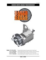
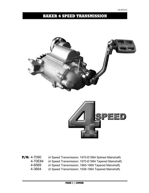
<strong>BAKER</strong> CRUISE 4 SPEED DRIVE TRANSMISSION TOP COVER<strong>V4</strong>-051013P/N: 4-7090 (4 <strong>Speed</strong> Transmission; 1970-E1984 Splined Mainshaft)4-70E84 (4 <strong>Speed</strong> Transmission; 1970-E1984 Tapered Mainshaft)4-6569 (4 <strong>Speed</strong> Transmission; 1965-1969 Tapered Mainshaft)4-3664 (4 <strong>Speed</strong> Transmission; 1936-1964 Tapered Mainshaft)PAGE 1 | COVER
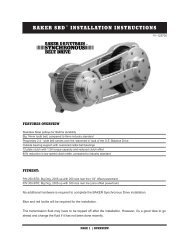
<strong>BAKER</strong> 4 SPEED OVERVIEW<strong>V4</strong>-051013FEATURESWe understand the love affair with your vintage motorcycle, there’s nothing like putting authentic,vintage styled components on your nostalgic bike. That’s why <strong>BAKER</strong> has taken the time toreinvent the 4 <strong>Speed</strong>. A vintage styled <strong>BAKER</strong> cast aluminum (A356-T6) transmission case,designed for traditional gear drive speedo pick up and a modern late model electronic speedopick up. Vintage style <strong>BAKER</strong> billet aluminum (6061-T6) top cover with linear detent system forthat smooth reliable shift quality you have come to expect from <strong>BAKER</strong>. <strong>BAKER</strong> Klassic KickerGears come standard on kicker models; modern <strong>BAKER</strong> 4 <strong>Speed</strong> Gearset made out of highgrade 8620 gear steel, all gears ride on needle bearings; no more brass bushings here. Directbolt-in transmission for most applications.FITMENT• 1936-E1984 FL ® /FX ® Shovelhead ® , Panhead ® , Knucklehead ® , Sturgis Shovelhead ®• Custom ApplicationsTOOLS REQUIRED• Torque Wrench (reads both in. lbs. and ft. lbs.)• Common Hand Held Tools (Allen Wrenches, Sockets, Snap Ring Pliers, Etc.)• Main Drive Gear & Bearing Service Toolso <strong>BAKER</strong> pn Tool Ao H-D® Equivalent pn 35316A• Pulley Nut Socketo <strong>BAKER</strong> pn TOOL Do H-D® Equivalent pn 94660-37B• Fork Shifter Gaugeo H-D ® P/N 96384-39o JIMS ® P/N 16-0641SPECIFICATIONS• TRANSMISSION FLUID CAPACITY: 22-24 fluid oz. <strong>BAKER</strong> Recommends: Spectro HeavyDuty Platinum 6 <strong>Speed</strong> Transmission Oil, pn BD-75140• COUNTERSHAFT END PLAY: .007”-.012”• 2 nd GEAR END PLAY: .003”-.010”• 3 rd GEAR END PLAY: .003”-.010”• 1 st /2 nd AND 3 rd /4 th SHIFT DOG TOOTH GAP: .060” per side• SHIFT DRUM END PLAY: .0005”-.0065”• RATCHET PAWL ADJUSTMENT: Per Your Factory Service ManualGEAR RATIOS1 ST 2.502 ND 1.703 RD 1.254 TH 1.00PAGE 2 | OVERVIEW - SPECIFICATIONS
<strong>BAKER</strong> 4 SPEED DRIVE GEAR RATIOS<strong>V4</strong>-051013SPEEDOMETER GEAR DRIVE<strong>BAKER</strong> 4 <strong>Speed</strong> Transmissions all come with a gear drive speedometer ring gear installed on thegearset. Using the list below; pending the year and model of you motorcycle you will have to usethe following gear drive unit OEM part number or equivalent for your speedometer to functioncorrectly.Year <strong>Speed</strong>ometer Drive Ratio OEM Drive Unit PN1936-61 2:1 Ratio, 7 Tooth Drive Ring Gear 67130-36 (11 Tooth Drive Unit)1962-67 1:1 Ratio, 4 Tooth Drive Ring Gear 67130-61 (13 Tooth Drive Unit)1968-80 1:1 Ratio, 7 Tooth Drive Ring Gear 67130-69 (23 Tooth Drive Unit)1947-61 FL Models use a 2:1 Ratio <strong>Speed</strong>ometer1962-80 FL Models, 1971-72 FX Models and 1980-83 Models use a 1:1 Ratio <strong>Speed</strong>ometer<strong>BAKER</strong> 4-<strong>Speed</strong> part numbers and default speedometer gear drive configurations listedbelow unless specified by customer that they are using the 1962-67 ratio as specifiedabove.<strong>BAKER</strong> Default <strong>Speed</strong>ometer configurations unless specified:Year <strong>Speed</strong>ometer Drive Ratio OEM Drive Unit PN4-3664 2:1 Ratio, 7 Tooth Drive Ring Gear 67130-36 (11 Tooth Drive Unit)4-6569 1:1 Ratio, 7 Tooth Drive Ring Gear 67130-36 (11 Tooth Drive Unit)4-70E84 1:1 Ratio, 7 Tooth Drive Ring Gear 67130-69 (23 Tooth Drive Unit)4-7090 1:1 Ratio, 7 Tooth Drive Ring Gear 67130-69 (23 Tooth Drive Unit)ELECTRONIC SPEEDOMETER SENSOR OPTIONOn 1965-E84 <strong>BAKER</strong> 4-<strong>Speed</strong> Transmission Cases (Ear Version Cases) you have the option touse a modern electronic speed senor. The transmission will house any Big Twin H-D ® style speedsensor from 1996-2006. For installation of the electric speed sensor see page 17.• <strong>Speed</strong> Sensor, Electronico H-D ® pn 74437-96• <strong>Speed</strong>ometer Recalibration Boxo <strong>BAKER</strong> pn 95E-56APAGE 3 | SPEEDOMETER DRIVE UNITS – ELECTRIC SENSOR
<strong>V4</strong>-051013<strong>BAKER</strong> 4 SPEED TORQUE VALUESTORQUE VALUESTHREADLOCKER / LUBRICANTRATCHET COVER• 10-24” Bolts: 45-50 in-lbs (3-4 ft-lbs) Blue Loctite ® (242 Removable)SHIFT LEVER• 10-24” Bolts: 40-45 in-lbs (3-4 ft-lbs) Blue Loctite ® (242 Removable)KICKER COVER• 5/16” Nuts: 200-225 in-lbs (16-18 ft-lbs) Blue Loctite ® (242 Removable)KICKER CRANK GEAR• 30-35 ft-lbs (40-47 Nm) Red Loctite ® (271 Permanent)TOP COVER• 1/4” Bolts: 100-120 in-lbs (8-10 ft-lbs) Blue Loctite ® (242 Removable)RETAINING PLATE, MAINSHAFT• 1/4” Bolts: 100-120 in-lbs (8-10 ft-lbs) Blue Loctite ® (242 Removable)MAINSHAFT NUT• 45-50 ft-lbs (61-67 Nm) Red Loctite ® (271 Permanent)RATCHET GEAR NUT• 50-60 ft-lbs (67-81 Nm) Red Loctite ® (271 Permanent)COUNTERSHAFT NUT• 30-35 ft-lbs (40-47 Nm) Red Loctite ® (271 Permanent)FILL PLUG• 30-40 in-lbs Pipe Thread SealantDRAIN PLUG• 30-40 in-lbs Anti-SeizeSPROCKET NUT• 50 ft-lbs (67.8 Nm) initial torque; then turn another 30-40 degrees; 45 degrees max.Red Loctite ® (271 Permanent)PAGE 4 | 4 SPEED TORQUE VALUES
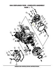
<strong>BAKER</strong> 4 SPEED EXPLODED VIEWSReplica Cast and Chrome styled Kicker Covers<strong>V4</strong>-051013FIGURE 1PAGE 5 | 4 SPEED KICKER COVER EXPLODED VIEW
<strong>BAKER</strong> 4 SPEED EXPLODED VIEWSRatchet Style Top Cover<strong>V4</strong>-051013FIGURE 2PAGE 7 | RATCHET TOP COVER EXPLODED VIEW
<strong>V4</strong>-051013<strong>BAKER</strong> 4 SPEED PARTS DETAIL FIGURE 2ITEM QTY PN DESCRIPTION1 3 / 4 10C50KFC0Z 10-24 X .500” FHCS, Lever2 1 1-26 / 1-27 Shift Lever3 1 ******** Dust Cover4 5 10C150KFCS 10-24 X 1.5” FHCS, Cover5 1 10C125KFCS 10-24 X 1.250” FHCS, Cover6 1 133-4R / 133-4B / 133-4P Cover, Ratchet7 1 158-4GAS Gasket, Ratchet Cover8 1 34498-52 Bushing, Ratchet Carrier9 2 18R37PDO 3/16” X .375” Solid Dowel10 1 132-4-BO Ratchet Carrier11 1 6C43MXF0Z 6-32 X .4375” FHMS12 1 34525-54 Pawl Retainer13 2 6R25PRP0P Roll Pin, 1/16” X .250”14 2 34482-53 Spring, Shifter Pawl15 2 34478-75 Pawl, Center Groove16 1 25C50KCS 1/4-20 X .500” SHCS17 2 LC055G12M Spring, Carrier Return18 1 135-4-BO Stop, Carrier Spring19 1 131-4-HA Backing Plate, Ratchet20 1 10CNMSS 10-24 Nut, Ratchet Cover21 1 134-4 / 160N1-4 Ratchet Shaft22 1 155-4GAS Gasket, Backing Plate23 1 50F37KKCS 1/2-20 X .375” Set Screw24 1 34435-52 Bushing, Ratchet Shaft25 1 128-4 Drum Rod (4.750” Long)26 1 33390-26 Spring, Ratchet Gear27 1 136FL-4 / 137FX-4 / 138N1-4 Ratchet Gear28 1 9R100PCO0P Cotter Pin, 3/32” X 1”29 2 PAPZ0606P10 Permaglide ® Bushing30 1 122FL-4 / 123N1-4 / 124FX-4 Shift Drum31 1 156-4GAS Gasket, Top Cover32 1 121-4R / 121-4B / 121-4P Top Cover33 10 25C100KFCS 1/4-20 X 1” FHCS SS34 1 F-232097 Linear Detent35 1 126-4 Cap, Linear Detent36 2 25C200KFCS 1/4-20 X 2” FHCS SS37 1 33900-59 Neutral Switch*******= COMES WITH # 2PAGE 8 | RATCHET TOP COVER EXPLODED VIEW LEGEND
<strong>BAKER</strong> 4 SPEED EXPLODED VIEWSJockey Style Top Cover<strong>V4</strong>-051013FIGURE 3PAGE 9 | JOCKEY TOP COVER EXPLODED VIEW
<strong>BAKER</strong> 4 SPEED PARTS DETAIL FIGURE 3<strong>V4</strong>-051013ITEM QTY PN DESCRIPTION1 1 1-127 Shoulder Bolt w/Nut2 1 17-0500 Threaded Shift Lever3 1 66808 O-Ring, Buna #0144 1 34430-36-A Bushing, Jockey Top5 1 50F37KKCS 1/2-20 X .375” Set Screw6 1 128-4 Rod, Shift Drum7 1 33390-26 Spring, Shifter Gear8 1 136FL-4 / 138N1-4 Gear, Shift Drum9 1 9R100PCO0P Cotter Pin10 2 PAPZ0606P10 Bushing, Drum Rod11 1 122FL-4 / 123N1-4 Shift Drum12 1 156-4GAS Gasket, Top Cover13 1 159-4R / 159-4B / 159-4P Jockey Top Cover14 10 25C100KFCS 1/4-24 X 1.000” FHCS15 1 F-232097 Linear Detent16 1 126-4 Cap, Linear Detent17 2 25C200KFCS 1/4-24 X 2.000” FHCS18 1 33900-59 Neutral SwitchPAGE 10 | JOCKEY TOP COVER EXPLODED VIEW LEGEND
<strong>BAKER</strong> 4 SPEED EXPLODED VIEWSShift Fork Components; 1965-E84 Case Shown<strong>V4</strong>-051013FIGURE 4PAGE 11 | 4 SPEED SHIFT FORK EXPLODED VIEW
<strong>V4</strong>-051013<strong>BAKER</strong> 4 SPEED PARTS DETAIL FIGURE 4ITEM QTY PN DESCRIPTION1 1 10C25KLH 10-24 X .250” Low Head2 1 35211-91-6N4 Sprocket Nut3 1 23T-64 / 24T-64 Sprocket4 1 33334-4 Spacer, Sprocket5 1 11165A Quad Seal6 1 12044-4B Seal, Transmission Case7+ 2 66808 O-Ring, Buna #148+ 1 108-6EP <strong>Speed</strong>o Plug9+ 1 73753 ¼-20 x .625” BHCS10 1 157-4P <strong>Speed</strong>o Plug, Gear Drive11 1 10C50KBCS 10-24 x .500” BHCS12 1 50F37KKCS ½-20 x .375” Set Screw13 1 34179-KIT Nut w/ Washer Kit14 *** 6750 Shim, Shift Fork15 1 209760 3 rd & 4 th Shift Fork16 *** 6752 Shim Shift Fork17 2 6754 Washer, Shift Fork18 2 34168-39 Hat, Shift Fork19 2 34182-76 Finger, Shift Fork20 1 143-4-ROD Fork Rod; 5.850” Long21 1 209750 1 st & 2 nd Shift Fork***= QUANTITY WILL VARY+= WILL ONLY COME ON 1965-E84 TRANSMISSION CASESPAGE 12| 4 SPEED SHIFT FORK EXPLODED VIEW LEGEND
<strong>BAKER</strong> 4 SPEED EXPLODED VIEWSTransmission Case and Gearset<strong>V4</strong>-051013FIGURE 5PAGE 13 | 4 SPEED TRANSMISSION CASE EXPLODED VIEW
<strong>V4</strong>-051013<strong>BAKER</strong> 4 SPEED PARTS DETAIL FIGURE 5ITEM QTY PN DESCRIPTION1 4 25C75KCS 1/4-20 X .750” SHCS2 1 125-4-BO Retainer Plate3 1 See Page 12 Mainshaft Assembly4 1 144-4-1.25 3M 3 rd Gear Mainshaft5 1 35365-36 Thrust Washer, 3 rd Gear6 1 11067A Retaining Ring7 1 148-4 3/4 Dog Clutch, 3 rd & 4 th Gear8 2 SCE-1612 Caged Needle Bearing9 1 146-4 4M Main Drive Gear10 1 12044-4B Seal, Main Drive Gear11 1 300RRIB Beveled Snap Ring, 3”12 1 6009CE Bearing, Main Drive Gear13 1 36045-76 Case Bushing, Left Side14 2 31R50PDO 5/16” x 1/2” Solid Dowel15 1 36048-76A Case Bushing, Right Side16 *** 120-4R / 120-4B / 120-4P Transmission Case 1965-8516 *** 130-4R / 130-4B / 130-4P Transmission Case 1936-6417 1 292014 Lock Tab Countershaft18 1 292015 Nut, Countershaft19 1 35630-36 End Plate, Countershaft20 1 22H-S05M-CLR Zero Leak Drain Plug21 9 AV9676Z Stud, Side Cover22 5 AV9683Z Stud, Bottom Of Case23 1 See Page 12 Countershaft Assembly24 1 207770 Countershaft25 1 66810 O-Ring, Buna #1626 4+/- AV9686Z Stud, Transmission Case*** = CUSTOMER PREFERENCE; DEPENDS ON YEAR AND FINISH4+/- = WILL COME WITH CASE PN 120-4R / 120-4B / 120-4P ONLYPAGE 14 | 4 SPEED TRANSMISSION CASE EXPLODED VIEW LEGEND
<strong>BAKER</strong> 4 SPEED EXPLODED VIEWSTransmission Gearset<strong>V4</strong>-051013FIGURE 6PAGE 15 | 4 SPEED GEARSET EXPLODED VIEW
<strong>V4</strong>-051013<strong>BAKER</strong> 4 SPEED PARTS DETAIL FIGURE 6ITEM QTY PN DESCRIPTION1 1 168-6N4 Nut, Mainshaft2 1 35050-40 Lock Tab, Mainshaft3 1 6305Z Bearing, Mainshaft4 1 35100-79 Housing, Bearing5 1 145-4-2.50 1M2M 1 st & 2 nd Gear Cluster6 1 ******** Mainshaft7 1 FBNPF-263015Z Split Needle Bearing 3 rd Gear8 1 17-0094 / 17-9160 / 17-9161 <strong>Speed</strong>o Ring Gear9 1 35915-36 Thrust Washer Countershaft10 2 SCE-1212 Caged Needle Bearing11 2 100RRRI Retaining Ring; 1”12 1 140-4-1.25 3C4C 3 rd & 4 th Gear Countershaft13 1 BNH-600-361 Split Needle, 2 nd Gear14 1 141-4-1.70 2C 2 nd Gear Countershaft15 1 129-4 Thrust Washer, 2 nd Gear16 1 35810-36 Retaining Ring, 2 nd Gear17 1 147-4 1/2 Dog Clutch, 1 st & 2nd18 1 139-4 Thrust Washer, 1 st Gear19 1 142-4-2.50 1C 1 st Gear Countershaft20 1 K35X40X13H Needle Bearing, 1 st Gear21 1 --------- Thrust Washer, 1 st Gear******= MAINSHAFT PART NUMBERS: 149-4M/S (1970-E84 Splined M/S), 150-4M/S (1970-E84Tapered M/S), 151-4M/S (1965-69 Tapered M/S), and 152-4M/S (1936-64 Tapered M/S)---------= THRUST WASHER PART NUMBERS: 35883-36 (.095” Thick), 38582-36 (.090”Thick), and 38579-36 (.085” Thick)PAGE 16 | 4 SPEED GEARSET EXPLODED VIEW LEGEND
<strong>BAKER</strong> 4 SPEED SPEED SENSOR INSTRUCTIONSINSTRUCTIONSInstall the transmission per you Factory Service Manual;before you install the starter (electric start applicationsonly; 1965-UP).<strong>V4</strong>-0510131. With the Transmission in the bike frame and InnerPrimary mounted; Install the electronic speedsensor.a. Remove the speed sensor plug on thetransmission ear (rear left side oftransmission).b. Lubricate the speed sensor O-Ring withtransmission oil; install using Blue Loctite ®and torque the bolt to 110-120 in-lbs.2. Fit up the starter to the primary with a couple boltsto hold it into position; do not tighten, you will noticeif using a stock style starter that the housing of thestarter will hit the top of the speed sensor. You willhave to clearance the starter housing for properfitment (figures 7 & 8).3. Using a Sharpie ® mark the area where the startercontacts the speed sensor.4. Using a rat tail file or die grinder remove the materialon the starter housing until the starter clears thespeed sensor. You might have to do a couplechecks and remark the starter to make sure that youare taking enough material for proper fitment (figure8). You should have at least a 1/16” of clearancewhen done (figure 10).5. After starter fits properly continue with yourtransmission installation per your Factory ServiceManual.SHOWING FITMENT BEFORE MODIFICATION | FIGURE 7AREA OF CONCERN, BEFORE MODIFICATION | FIGURE 8STARTING TO TAKE MATERIAL OFF OF MARKED AREA | FIGURE 9 STARTER INSTALLED AFTER MODIFICATION | FIGURE 10PAGE 17 | 4 SPEED TRANSMISSION SPEED SENSOR INSTALL
<strong>V4</strong>-051013<strong>BAKER</strong> 4 SPEED – 1965-69 STOCK MODELSINSTALLATION SUPPORT FOR 1965-69 <strong>BAKER</strong> 4 SPEEDS<strong>BAKER</strong> 4 <strong>Speed</strong>s utilize an early 5 speed spline design forthe main drive gear. Using this design requires a slightlyoffset sprocket to wrap around the modern spacer anddrive gear. On 1965-69 models the stock inner primaryhas a lip which will hit the sprocket before going onto thetransmission all of the way. Following these instructionsand images, modify your stock H-D primary for properfitment. These instructions do not apply for aftermarketinner primaries or belt drive motor plates.Modification of stock 65-69 inner primary• Looking at figure 11 you can see the inner lip thathas to be machined down in order to clear thesprocket and sprocket nut.• Machine down this lip; measuring from the ears onthe primary down; finish machine should be: .560”/ .620” from the ear surface, figure 11. Notice thatthe threaded holes are now exposed on thecasting from machining, figure 12.• Chamfer the inner primary ears on the insideedge, breaking the edge .020/.030 X 45, figure 12.Make sure to test fit the primary onto thetransmission before running. Extra machiningclearance might be needed for proper fitment..560 / .620 DOWN FROM TOPSURFACE OF EARSSTOCK 65 INNER | FIGURE 11CHAMFER EAR EDGESMODIFIED 65 INNER | FIGURE 12• After making sure everything fits properly, usingfour 1/4-20 X .375” set screws plug off thethreaded holes. Apply some pipe thread sealanton the set screws then install from the inside,figure 13• Install the primary per your Factory ServiceManual.INSTALLING SET SCREWS | FIGURE 13PAGE 18 | 1965-69 PRIMARY INSTALLATION
<strong>V4</strong>-051013<strong>BAKER</strong> 4 SPEED TRANSMISSIONSPECIALORDERSA minimum $500 deposit is required with all special orders. Special orders include unique case finishes, unique side doorrequests (i.e.; wrinkle black door or no logo).ALL OTHER ORDERSOrders can be pre-paid using VISA, MasterCard or American Express.Prices shown are F.O.B. Haslett, MI. <strong>BAKER</strong> provides free UPS ground shipping on all retail orders for completetransmissions or transmission kit. UPS air shipment is available upon request. Customer is responsible for air shipmentpremiums.LIMITED WARRANTY<strong>BAKER</strong> Inc. transmission assemblies, transmission kits, and wide tire kits are guaranteed to the original purchaser to befree of manufacturing defects in materials and workmanship for a period of 5 years from the date of purchase or up to50,000 miles - whichever is sooner.If the product is found by <strong>BAKER</strong> to be defective, such products will, at the option of <strong>BAKER</strong>, be replaced or repairedat cost to <strong>BAKER</strong>.In the event warranty service is required, the original purchaser must call or write <strong>BAKER</strong> immediately with the problem.If it is deemed necessary for <strong>BAKER</strong> to make an evaluation to determine whether the transmission assembly ortransmission kit is defective, the entire transmission assembly, whether originally purchased as an assembly or kit, mustbe properly packaged and returned prepaid to <strong>BAKER</strong> with a copy of the original invoice of purchase.If after an evaluation has been made by <strong>BAKER</strong> and a defect in materials and/or workmanship is found, <strong>BAKER</strong> will,at <strong>BAKER</strong> option, repair or replace the defective part of the assembly.Warranty card must be returned within 45 days of purchase to be valid.ADDITIONALWARRANTY PROVISIONSThis limited warranty does not cover labor or other costs or expenses incidental to the repair and or replacement of<strong>BAKER</strong> products. This warranty does not apply if one or more of the following situations is judged by <strong>BAKER</strong> to berelevant: improper installation, accident, modification (including but not limited to use of unauthorized parts), racing, highperformance application, mishandling, misapplication, neglect (including but not limited to improper maintenance), orimproper repair.<strong>BAKER</strong> shall not be liable for any consequential or incidental damages arising out of or in connection with a <strong>BAKER</strong>transmission assembly, transmission kit, swingarm, fender, component or part. Consequential damages shall includewithout limitation, loss of use, income or profit, or losses sustained as the result of injury (including death) to any person orloss of or damage to property.<strong>BAKER</strong> transmissions, transmission kits, and Wide Tire Kits are designed exclusively for use in Harley-Davidson®motorcycles. <strong>BAKER</strong> shall have no warranty or liability obligation if a <strong>BAKER</strong> part is used in any other application.If it is determined that a <strong>BAKER</strong> transmission assembly has been disassembled during the warranty period for anyreason, this limited warranty will no longer apply.PAGE 19 | TERMS
<strong>V4</strong>-051013<strong>BAKER</strong> 4 SPEED TRANSMISSIONThe words Harley, and H-D are registered trademarks and are for reference only. Use of H-D model designations and partnumbers are for reference only. <strong>BAKER</strong> <strong>Drivetrain</strong> has no association with, and makes no claim against, these words,trademarks, or companies.It is the sole responsibility of the user to determine the suitability of this product for his or her use, and the user shallassume all legal, personal injury risk and liability and all other as well as all other obligations, duties and risks associatedtherewith.CUSTOMER SUPPORTFor any installation or service questions, please contact our <strong>BAKER</strong> technical department toll free: 1-877-640-2004.PAGE 20 | DISCLAIMER