DT591 User Manual - Schick Handel
DT591 User Manual - Schick Handel
DT591 User Manual - Schick Handel
- No tags were found...

You also want an ePaper? Increase the reach of your titles
YUMPU automatically turns print PDFs into web optimized ePapers that Google loves.
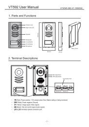
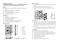
Door Camera - <strong>DT591</strong> <strong>User</strong> <strong>Manual</strong>ONON1 2Parts and functionsThe DT 591 is a special design for the DT 2-wire system:• Full matel cover with backlight nameplate• 4 Door cameras connection• Directly connect 2 separate electronic locks, unlock time controlled by MonitorCamera LensNight View LEDSpeaker176 mmNameNameplateCall ButtonMicrophone90 mm23 mmTerminal Descriptions1 2 3Lock Control Jumper1 2Camera Code DIPMIC adjustmentSPK adjustmentL1 L2 PL S1+ S2+ S-Main Connect PortDT - ENG - 591 - V1 1
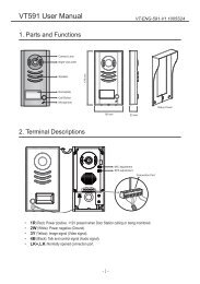
ON1 2CALLUNLOCKTALK/MONIN-USEMENUUnlockON1 2CALLUNLOCKTALK/MONIN-USEMENU• Lock Control Jumper: To configure the electronic lock safety type; set the jumper in 1-2 position for Powerto-Unlocktype(pulse activated electronic lock), set the jumper in 2-3 position for the Power-Off-to-Unlocktype(electromagnetic lock). Remove the jumper if using external power supply for the lock.(the power+ will beconnected to the PL on the Main Connect Port)• Camera Code DIP: To set the code for the door camera, total 4 cameras can be connected in the system; setto 00 for the master camera, set to 10 for the slave 2nd camera, set to 01 for the slave 3rd camera, set to 11 forthe slave 4th camera. Set to 00 if there is only one door camera used in the system.• Main Connect Port: To connect the bus line and the electronic locks.• L1, L2: Connect to the bus line, no polarity.• PL: External lock power input, connect to the power positive(power +).• S1+, S2+: Lock power(+) output, to connect 2 electronic locks.• S-: Lock power(-) output, connect to the power(-) input of electronic locks(only when using the camera to powerthe locks, if using the external power supply for the locks, the S- will not be connected)Inner Power 1 Lock ConnectionThe standard inner power lock connection, use the Camera power to supply the lock, no need for external powersupply. In this way, the Lock Control Jumper and Unlock Mode in the monitor need to be set: for Power-to-Unlocktype electronic lock, set to position 1-2 and Unlock Mode 0(in Monitor, goto Main--> Setup--> Advanced Set-->Information page, then press and hold the Unlock Button for 2 seconds to open the Unlock Mode setting page); forPower-Off-to-Unlock type electromagnetic lock, set to position 2-3 and Unlock Mode 1.1 2 3Jumper position in 1-21 2 3Jumper position in 2-3Unlock Mode: 0Mode: 1L1 L2 PL S1+ S2+ S-Electronic lockSafety Type: Power-on-to-openThe lock consumption must notgreater than 12V 500mA.L1 L2 PL S1+ S2+ S-ElectronMagnetic lockSafety Type: Power-off-to-openThe lock consumption must notgreater than 12V 500mA.--to Monitor+to Monitor+2
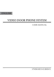
ON1 2ON1 2CALLUNLOCKTALK/MONIN-USEMENUUnlockCALLUNLOCKTALK/MONIN-USEMENUUnlockON1 2ON1 2CALLUNLOCKTALK/MONIN-USEMENUCALLUNLOCKTALK/MONIN-USEMENUInner Power 2 Locks ConnectionDirectly connect 2 electronic locks to the door station and use the Camera power to supply the locks. There are 2separate unlock icons on Monitor for opening each lock. Note that the 2 locks should be the same safety type.1 2 3Jumper position in 1-21 2 3Jumper position in 2-3Unlock Mode: 0Mode: 1L1 L2 PL S1+ S2+ S-Electronic lockSafety Type: Power-on-to-openThe lock consumption must notgreater than 12V 500mA.-lock #2L1 L2 PL S1+ S2+ S-ElectronMagnetic lockSafety Type: Power-off-to-openThe lock consumption must notgreater than 12V 300mA.-lock #2to Monitor+-lock #1to Monitor+-+lock #1+External Power ConnectionUse external power supply to power the electronical locks, in this way, wide range lock from 5V to 48 V electroniclocks can be used in the system. Note that in this case, the Lock Control Jumper is removed in both lock type.1 2 3Jumper removed1 2 3Jumper removedUnlock Mode: 0Mode: 1L1 L2 PL S1+ S2+ S-Electronic lockSafety Type: Power-on-to-openThe lock consumption must notgreater than 48V 1.5A.L1 L2 PL S1+ S2+ S-ElectronMagnetic lockSafety Type: Power-off-to-openThe lock consumption must notgreater than 48V 1.5A.to Monitor+to Monitor+---+Adaptor- +DT - ENG - 591 - V1 3
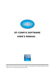
Mounting Without Rain Cover1 2 3 41160-165cm2Mounting With Rain Cover1 2 3 412160-165cmElectronic SpecificationsLock Power supply:12Vdc, 500mA(supplied by system)Power Consumtion:1W in standby, 12W in workingVideo signal:1V p-p 75 ohm CCIRNO, COM exchange contact: Max. 48V dc 1.5AUnlocking time:1 to 9 seconds, set by MonitorWorking temperature:-5ºC +45ºC4