Rover 75 Owner's Handbook - 3rd Edition - Eng - RoverClub-BG.com
Rover 75 Owner's Handbook - 3rd Edition - Eng - RoverClub-BG.com
Rover 75 Owner's Handbook - 3rd Edition - Eng - RoverClub-BG.com
- No tags were found...

Create successful ePaper yourself
Turn your PDF publications into a flip-book with our unique Google optimized e-Paper software.
Owner’s <strong>Handbook</strong>InstruktieboekjeManuel du ConducteurBetriebsanleitungManuale di IstruzioniManual del ConductorManual do Proprietário
Owner’s <strong>Handbook</strong>Publication Part No. RCL 0306ENG - <strong>3rd</strong> <strong>Edition</strong>Published by <strong>Rover</strong> Group After Sales - Technical Communication© <strong>Rover</strong> Group Limited 1999All rights reserved. No part of this publication may be reproduced, stored in a retrieval system or transmitted in any form, electronic, mechanical,recording or other means without prior written permission from <strong>Rover</strong> Group Limited.As part of <strong>Rover</strong> Cars environmental policy, this publication is printed on paper made from chlorine free pulp.
Congratulations on your choice of a <strong>Rover</strong> <strong>75</strong>We very much hope that this handbook, together with the other publicationsincluded in the literature pack, will provide the information you need in order toderive maximum pleasure from owning and driving your new car.For your convenience, the handbook is divided into sections, each dealing with adifferent aspect of driving or caring for the car. Take a little time to read each oneand get to know your new <strong>Rover</strong> as soon as you possibly can.• ‘Before you drive’ - includes seat adjustment, seat belts and heating controlsand deals with everything you need to know in order to settle <strong>com</strong>fortably intothe car before you drive.• ‘Driving controls’ - here the functions and operation of the switches,instruments and driving controls are explained.• ‘Maintenance’ - includes information about the checks that you should carryout on a regular basis.• ‘Emergency information’ - will help to solve some of those unavoidablelittle emergencies that occur from time to time, like replacing bulbs and fuses,or changing a wheel.• ‘Technical Data’ - includes the technical specification for your car.This warning symbol identifies procedures that must be followed precisely, orinformation that must be considered with great care, in order to reduce the riskof personal injury or serious damage to the car.This symbol identifies those features that can be adjusted or disabled/enabled bya <strong>Rover</strong> dealer.An asterisk appearing in the text, identifies features or items of equipment thatare either optional, or are only fitted to some cars in the model range.IMPORTANTThe specification of each <strong>Rover</strong> vehicle will vary according to territorial requirements and alsofrom model to model within the vehicle range. Some of the information published in thishandbook, therefore, may not apply to your vehicle. Contact your dealer if you are in anydoubt.<strong>Rover</strong> operate a policy of constant product improvement and therefore reserve the right to change specifications without notice at any time.Whilst every effort is made to ensure <strong>com</strong>plete accuracy of the information in this handbook, no liabilities for inaccuracies or the consequencesthereof, including loss or damage to property, or injury to persons, can be accepted by the manufacturer or the dealer who supplied thehandbook, except in respect of personal injury caused by the negligence of the manufacturer or dealer.2
Contents1 32BEFORE YOU DRIVEControls ........................................ 4Locks & Alarm .............................. 5Seats ............................................ 17Seat Belts ..................................... 24Airbag SRS .................................. 30Steering Column ......................... 38Mirrors ........................................ 39Windows ..................................... 43Sunroof ....................................... 45Heating & Ventilation ................. 47Interior Equipment ...................... 57Audio System .............................. 65In-Car Telephones ...................... 66Load Carrying ............................. 67Towing ....................................... 71DRIVING CONTROLSInstruments .................................. 72Trip Computer ............................ 76Warning Lights ............................ 79Message Centre ........................... 86Starting & Driving ....................... 95Environmental Driving ................ 99Catalytic Converter ................... 101Automatic Transmission ............. 103Manual Gearbox ........................ 109Fuel System ............................... 110Lights & Indicators ..................... 114Horn ......................................... 120Wipers & Washers ..................... 121Cruise Control .......................... 123Brakes ........................................ 125Traction Control ....................... 130Parking Aid ............................... 13245MAINTENANCEMaintenance ...............................134<strong>Eng</strong>ine Compartment .................139<strong>Eng</strong>ine ........................................143Cooling System ..........................145Brakes ........................................147Power Steering ...........................148Battery .......................................150Washers ......................................154Wipers ........................................155Tyres ..........................................156Cleaning & Vehicle Care ............159EMERGENCY INFORMATIONWheel Changing ........................163Emergency Starting ....................168Vehicle Recovery .......................171Fuses ..........................................174Bulb Replacement ......................179Parts & Accessories .....................191Identification Numbers ...............192TECHNICAL DATATechnical Data ...........................194Index...........................................205
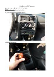
ControlsBEFORE YOU DRIVEControls1 2 3 4 5 6 7 8 9 10 11 12 13H274426 25 2423222120191817 1615141. Passenger airbag SRS2. Audio system3. Clock4. Horn5. Direction indicators6. Instrument panel7. Driver airbag SRS8. Starter switch9. Wiper/washer controls10. Front* and rear fog light switches11. Main lighting switch12. Bonnet release13. Mirror controls14. Window controls15. Boot release16. Headlight adjuster17. Instrument dimmer control18. Cruise control switches*19. Steering column adjustment lever20. Audio controls21. Heating/air conditioning controls22. Switch panel23. Hazard warning light switch24. Interior door lock switch25. Gear lever26. Handbrake4
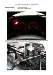
Locks & AlarmLocks & AlarmALARM SYSTEMYour car is fitted with a sophisticated electronic anti-theftalarm and engine immobilisation system. There are also anumber of additional security features, some of which areselectable options. In order to ensure maximum security andoperating convenience, you are strongly advised to gain a fullunderstanding of the features and alternatives available, bythoroughly reading this section of the handbook.1NOTE: FOR MAXIMUMSECURITY ALWAYSSUPERLOCK THE VEHICLEUSING THE REMOTE HANDSET(except when passengers are tobe left inside the car).LockingH2698With the remote handset:1. Shut the doors, bonnet and luggage <strong>com</strong>partment.2. Press the lock (padlock symbol) button once:• all doors are superlocked (see ‘Superlocking’)• perimetric alarm activated (protects the doors,bonnet and boot)• interior space protection activated*3. The direction indicator lights flash three times to confirmthat the car is securely locked and the anti-theft alarmindicator light (in the instrument panel) starts to flash.5
Locks & AlarmWith the key:1. Insert the key and turn the door lock towards the rear ofthe car:• all doors locked (not superlocked)• perimetric alarm activated (protects the doors,bonnet and boot)• NO INTERIOR SPACE PROTECTION2. The direction indicator lights flash three times to confirmthat the car is securely locked and the anti-theft alarmindicator light (in the instrument panel) starts to flash.Operating tip: Locking with thekey will not activate superlocking.UnlockingWith the remote handset:• Press the unlock (<strong>Rover</strong>) button once. This will disarm thealarm and unlock the driver’s door only (see ‘Single pointentry’).• Press the unlock button twice to disarm the alarm andunlock ALL the doors.In either case, the direction indicator lights flash once andthe interior lights illuminate.With the key:• Turn the key in the driver’s door lock towards the front ofthe car to disarm the alarm and unlock the driver’s dooronly (see ‘Single point entry’).• Turn the key twice (or press the interior locking button),to unlock ALL the doors.Using the remote handsetWhile it is not necessary to point the handset at the car, thehandset must be within range when the buttons are pressed.Note that the operating range may vary depending uponhandset battery condition and may sometimes be limited byphysical and geographical factors beyond your control. Froma security point of view, it may not be wise to unlock unlessyou are within a few feet of the car.6
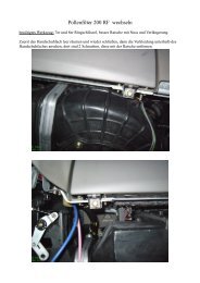
Locks & AlarmSuperlockingProvided all the doors are fully closed, the superlockingfeature is activated automatically whenever the car is lockedusing the remote handset. Superlocking immobilises theinterior door handles, thereby preventing an intruder fromgaining entry by smashing a window and reaching inside thecar to operate the door handles.Anti-theft alarm indicator light1For safety, NEVER useSuperlocking ifpassengers are to remain insidethe car - in an emergency theywould not be able to escape.Also, on cars fitted with interiorspace protection, anymovement from inside the carwould activate the alarm.H27<strong>75</strong>This light provides information about the status of the alarmsystem, as follows:• When the alarm is armed:The light flashes RAPIDLY while the alarm is armingitself. After ten seconds, the light adjusts to a slowerfrequency and continues to flash as an anti-theft deterrentuntil the alarm is disarmed.• When the alarm is partially armed: (mislock)The light flashes SLOWLY for 10 seconds, then flashes asan anti-theft deterrent (as above) until the alarm isdisarmed.• When the alarm has been triggered:If the light flashes after the car is unlocked, this indicatesthat the alarm has been triggered during the driver’sabsence. The light will flash for up to one minute or untilthe starter switch is turned on.7
Locks & Alarm1Interior locking switchH2781This is a personal security feature which allows the driver tolock (or unlock) all the doors from inside the car (whiledriving or with the car stationary). Press the closed padlocksymbol on the switch to lock (the alarm will not be armed),and the open padlock symbol to unlock.NOTE: The locking switch will notoperate the locks if the alarm hasbeen armed.Interior door handles and door sill locking buttonsFrom inside the car, each door can be individually locked bydepressing the appropriate door sill button. However, doorscannot be unlocked by raising the sill button.Use the door handles to unlock, as follows:1. First operation of the door handle unlocks the door.2. Second operation of the door handle opens the door.Speed-related locking*This security feature locks all the doors automatically whenthe road speed exceeds 4 mph (7 km/h).Note that this feature is not selectable by the driver, and thatoperation of the door locks by any other means (interiorlocking switch on the centre console, for example) willdisable the speed-related locking function for the remainderof the journey, or until the starter switch is turned off and onagain.Speed related locking canbe selected or deselectedby a <strong>Rover</strong> dealer.9
Locks & AlarmInterior space protection*Never activate interiorspace protection ifpassengers are to be left insidethe car - any movement willactivate the alarm.H2700Interior space protection (ultrasonics) is designed to protectthe interior of the car from intrusion (entry by a thief througha smashed window, for example). A pair of ultrasonic sensorsmonitor the interior space and activate the alarm if airmovement is detected in the passenger <strong>com</strong>partment.Using the handset: Interior space protection is activatedautomatically whenever the remote handset is used to set thealarm.Key operation: Using the key will NOT activate interiorspace protection.NOTE: Interior space protectioncannot be activated if a door,window or sunroof is open, or ifthe starter switch is turned on.ENGINE IMMOBILISATION<strong>Eng</strong>ine immobilisation is an important aspect of the securitysystem, it is designed to safeguard the vehicle from theft,should the driver forget to lock the doors and prevents theengine from being started unless the GENUINE handset keyis inserted into the starter switch. <strong>Eng</strong>ine immobilisation isautomatic whenever any of the following conditions occur.• Three seconds after the starter switch has been turned off.• If the key is removed from the starter switch.The engine will be re-mobilised automaticallywhenever the genuine handset key is inserted into thestarter switch and turned to the first position.NOTE: If the handset is lost orfails to operate, the emergencykey can be used to re-mobiliseand start the engine.10
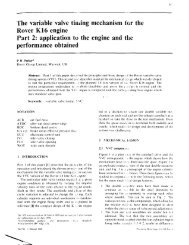
Locks & AlarmREMOTE HANDSET BATTERYThe battery should last for approximately three yearsdependent upon use. Always fit a <strong>Rover</strong> YWK10003 or aPanasonic CR2032 replacement battery (available from a<strong>Rover</strong> dealer).When the battery needs replacing it will be apparent from agradual deterioration in range and performance.On cars fitted with a message centre, a warning icon andmessage will be displayed when the battery needs replacing(see ‘Message centre’).1The handset containsdelicate electroniccircuits and must be protectedfrom impact and water damage,high temperatures andhumidity, direct sunlight andthe effects of solvents, waxesand abrasive cleaners.Battery renewalH26921. Insert the blade of a small flat-bladed screwdriver into theslot at the rear of the handset (see illustration) and prisethe rear of the back upwards.2. Insert the screwdriver blade horizontally into the side ofthe handset and then slide it towards the key. Lift off theback of the handset.3. Use a small flat-bladed screwdriver to prise the batteryfrom its mounting (see illustration), taking care to avoidtouching the circuit board or the metal battery contacts.11
Locks & Alarm4. Fit the new battery, ensuring that correct polarity ismaintained (‘+’ side facing up).5. Press the two halves of the handset firmly together andensure that both halves are fully joined to prevent dirt ormoisture from entering the handset.6. To resynchronise the handset, operate either button fourtimes in quick succession. On the fourth press the doorshould lock or unlock, confirming resynchronisation.The handset is now ready for use.Care point: Finger marks willadversely affect battery life; ifpossible, avoid touching the flatsurfaces of the battery and wipethem clean before fitting.12
Locks & AlarmKEYS AND HANDSETSYou have been supplied with two remote handsets withintegral keys which operate all locks.The keys supplied with your car are programmed to yoursecurity system - they CANNOT be re-programmed and theengine cannot be started without a key programmed to yourcar. If a key is lost or broken, a replacement can only beordered from a <strong>Rover</strong> dealer.If you lose a key, contact your <strong>Rover</strong> dealer; a key reportedlost will be deactivated. If the key is recovered, your <strong>Rover</strong>dealer can have it reactivated.1Keep the spare handsetkey in a safe place - NOTIN THE VEHICLE!NOTE: <strong>Rover</strong> dealers do not stockspare keys, time has to beallowed for replacements to beprogrammed to your securitysystem and then delivered to thedealer.13
Locks & AlarmLUGGAGE COMPARTMENTDo not drive with theluggage <strong>com</strong>partmentopen, as poisonous exhaustgases will enter the car.H2706To open, turn the key clockwise in the lock or, from insidethe car, press the release button in the driver’s footwell. Theluggage <strong>com</strong>partment and interior lights switch onautomatically when the boot lid is opened.The luggage <strong>com</strong>partment is automatically locked when theboot lid is closed.For convenience, with the alarm system armed, the luggage<strong>com</strong>partment can be unlocked and opened USING THEKEY, without activating the alarm (the rest of the car willremain protected and the engine immobilised during thisprocess). The alarm will automatically rearm as soon as theboot lid is closed.Operating tip: The interiorrelease button is not operationalwhen the alarm system is armed.14
Locks & Alarm1CHILD-PROOF LOCKSNEVER leave childrenunsupervised in thevehicle.H2691Move the locking levers on the rear doors down to engagethe child locks.With the child-proof locks engaged, the rear doors cannot beopened from inside the car, thereby avoiding the risk of adoor being opened accidentally while the car is moving.15
Locks & AlarmDOOR LOCKING CUT-OFF SWITCHH2682An inertia switch, operational only with the alarm disarmed,will unlock the doors in the event of an accident or suddenimpact.When the switch operates, the interior lights illuminate untilthe system is reset by pressing the rubber top (arrowed inillustration). In addition, the hazard warning lights flash untilswitched off.The inertia switch is located behind the glovebox and can bereached from underneath by releasing the four fixingssecuring the access cover.The inertia switch also cuts off the fuel supply (see ‘Fuel cut-offswitch’).Always check for fuelleaks before resetting theswitch!16
SeatsSeatsMANUALLY OPERATED FRONT SEATS*Forward/rearward adjustment1Your car is fitted with sideimpact airbags. Refer tothe Airbag SRS section of thishandbook before fitting seatcovers, or carrying out anyrepair or retrimming operationsto the seat or seat covers.H2746Lift the lever and slide the seat into position. Make sure theseat is locked in position before driving.Height adjustment (Driver’s seat only)DO NOT adjust the seatswhile the car is moving.Take care when adjustingthe height of the driver’sseat - a rear seat passenger’sfeet might be<strong>com</strong>e trappedwhen lowering the seatrearwards.H2745Ensure the seat is occupied before adjusting the height. Liftthe lever and apply weight to lower the seat rearwards, orallow the seat to rise forwards, as required.Operating tip: While adjustingthe height, grip the steeringwheel to more accurately controlthe rate of rise and fall.17
SeatsBackrest adjustmentDO NOT allow front seatoccupants to travel withthe seat backs reclined steeplyrearwards. Optimum benefit isobtained from the seat belt withthe backrest angle set toapproximately 25° from theupright (vertical).H2747Rotate the handwheel to adjust.Lumbar support adjustment*H2748Rotate the handwheel to increase or decrease support to thelumbar region of the back.18
Seats1HEAD RESTRAINTSHead restraints are designed to restrain rearward movement ofthe head in the event of an accident or sudden stop - aproperly adjusted head restraint can considerably reduce therisk of neck and head injuries.Head restraint adjustmentNOTE: Where possible, adjust thehead restraint so that the cushionis level with the back of the head- NOT THE NECK!H3248Raise or lower the restraint until the cushion is level with theback of the head.To lower the restraint, depress the button (arrowed) and pushthe restraint downwards. To raise the restraint, pull therestraint upwards without depressing the button.On some models the angle of the restraint can be adjusted.Tilt the restraint to ensure it is as close to the back of the headas possible.To remove the head restraint, depress the button on the lefthand mounting and pull the restraint upwards.19
SeatsPOWER-OPERATED FRONT SEATS*Seat adjustment is available when the starter switch is in thesecond position.If the driver’s seat is equipped with the memory facility, it canalso be adjusted when the starter switch is in the first position,or with a front door open when the starter switch is off.Information on operating the heated front seats* can befound in the ‘Heating & ventilation’ section of the handbook.Your car is fitted with sideimpact airbags. Refer tothe Airbag SRS section of thishandbook before fitting seatcovers, or carrying out anyrepair or retrimming operationsto the seat or seat covers.Forward/rearward adjustmentH2<strong>75</strong>0Push and hold the switch forwards or rearwards to move theseat to the desired position.DO NOT adjust the seatswhile the car is moving.Lumbar support and head restraintsFor information on adjusting lumbar support and headrestraints, please refer to ‘Manually operated front seats’, earlierin this section.20
SeatsSeat cushion angle (Driver’s seat only)1DO NOT adjust the seatswhile the car is moving.H2<strong>75</strong>2aPush the front of the switch up or down to tilt the seatcushion to the desired position.Seat cushion height (Driver’s seat only)H2<strong>75</strong>3Push the switch up or down to raise or lower the cushion.21
SeatsBackrest adjustmentDO NOT allow front seatoccupants to travel withseat backs reclined steeplyrearwards. Optimum benefit isobtained from the seat belt, withthe backrest angle set toapproximately 25° from theupright (vertical).H2<strong>75</strong>4Twist the switch forward or backwards until the desired angleis achieved.22
SeatsDRIVER’S SEAT MEMORY FACILITY*1DO NOT adjust the seatswhile the car is moving.Before activating the seatmemory and lazy seat functions,ensure that the areaimmediately surrounding theseat is clear of obstructions andthat all occupants are clear ofmoving parts.H2<strong>75</strong>5Your car can memorise three different driver seatingpositions. To store the positions in the system memory, thestarter switch must be turned to the first or second position.Adjust the seat to the required position and store the settingsby pressing and holding the memory store switch (‘M’) and,with the memory store switch still depressed, press and releaseone of the pre-set buttons (‘I’, ‘II’ or ‘III’). Finally, release thememory store switch; a single chime will sound to confirmthat the operation was successful.To recall a stored position after the seat has been moved byanother driver, open the driver’s door and press theappropriate memory pre-set button. The seat will return tothe position stored by that memory pre-set, a double chimewill sound to confirm that the operation is <strong>com</strong>plete.Lazy seatsThe lazy seat facility enables the handsets or keys to be usedto recall seat positions, when you unlock the doors.Press and hold the handset unlock button or turn and hold thekey in the unlock position, the driver's seat moves to theposition stored in pre-set 1. An alternative driver's setting canbe programmed using pre-set 2. As before, position the seatand programme pre-set 2 then, when the spare key is used toactivate ‘Lazy seats’, pre-set 2 will be selected.Operating tip: If a pre-set isselected accidentally, stop seatmovement by pressing any of theseat control buttons.NOTE: If the car is in motion, thepre-set will need to be pressedand held for the seat to move.This is to prevent inadvertentoperation of the memorypre-sets, which could cause theseat to move into a position inwhich the driver is unable to drivesafely.23
Seat BeltsSeat BeltsSEAT BELT SAFETYThe seat belts fitted to your car are intended for use by adultsized occupants and must be used by one occupant only.Ensure that all passengers are correctly strapped in at all timesand be sure to observe the following precautions:• DO NOT allow occupants to travel with the seat backsreclined steeply rearwards. Optimum benefit is obtainedfrom the seat belt with the backrest angle set toapproximately 25° from the upright (vertical).• Adjust seat belts to eliminate any slack. Do not pull the beltaway from the body while travelling - to be fully effective,the seat belt must remain in full contact with the body atall times.• Fit the lap strap across the PELVIS (never across theabdomen), ensuring that the diagonal strap passes acrossthe CHEST and SHOULDER without bearing on theneck.• DO NOT wear seat belts over hard, sharp or fragile itemsin clothing, such as pens, keys, spectacles etc.• Ensure that seat belts are not twisted or obstructed in anyway.• Always replace a seat belt assembly that has withstood thestrain of a severe vehicle impact, or if the webbing showssigns of fraying.• Where possible, use the seat belts to secure luggage carriedon the seats - in an accident, loose items can be thrownaround inside the car, causing serious injury.• In most countries, all occupants are required by law towear a seat belt, unless they have been issued with amedical exemption certificate.• During pregnancy, women should wear the lap belt acrossthe hips below the baby, with the diagonal belt passingacross the shoulder, between the breasts and to one side ofthe baby - if in doubt, consult a doctor.The airbag supplementaryrestraint system (SRS) isdesigned to add to the overalleffectiveness of the seat belts. Itdoes not replace them. SEATBELTS MUST ALWAYS BEWORN!24
Seat BeltsSEAT BELTSTo minimise injury in the event of an accident, it isimportant that seat belts are worn correctly. Read theinstructions below and the advice contained under theheading ‘Seat belt safety’ on a previous page.Fastening the belt1Ensure that all seat beltsare worn correctly - animproperly worn seat beltincreases the risk of death orserious injury in the event of acollision.H2731Pull the seat belt steadily over the shoulder and across thechest and, ensuring the webbing is not twisted, insert themetal tongue plate into the appropriate buckle - a ‘click’indicates that the belt is securely locked.Seat belts are designed to bear upon the bony structure of thebody (pelvis, chest and shoulders) and can only be worn safelywith the seats in a near-upright position; DO NOT allow thefront passenger to travel with the seat steeply reclined (see also‘Seating positions’ in the ‘Airbag SRS’ section of thishandbook).NOTE: Do not allow foreignmatter (particularly sugary foodand drink particles) to enter theseat belt buckles - suchsubstances can render thebuckles inoperative.NOTE: Where possible, rear seatpassengers should adjust theirposition to enable the seat beltwebbing to cross the shoulderwithout pressing on the neck.Releasing the beltPress the red button on the seat belt buckle.25
Seat BeltsUpper anchorage height adjustmentTo reduce the likelihood of injury in an accident, the heightof the front seat belt upper anchorage adjusts automatically asthe seat is moved either forwards or backwards. The heightCANNOT BE ADJUSTED MANUALLY!CHILD SEATSChildren are more likely to receive injuries from inflatingairbags than taller occupants (see ‘Airbag SRS’). For thisreason, it is re<strong>com</strong>mended that children should always beseated in the rear of the vehicle, in a child safety seat orrestraint system appropriate to their age and size. The range ofsafety seats approved for use in your car is outlined in the<strong>Rover</strong> accessories brochure, which is available from your<strong>Rover</strong> dealer.For optimum protection, it is re<strong>com</strong>mended that childrenweighing up to 13 kg (29 lb - or approximately 18 months ofage) are restrained in a <strong>Rover</strong> approved rear facing child seatin an outer rear seating position.All infant and child restraint systems are designed to besecured in the car by means of an adult seat belt.When installing and using any infant or child restraint system,always follow the manufacturer’s instructions. Failure toproperly secure the child restraint system can endanger thechild in a collision or sudden stop and cause injury to otherpassengers.NOTE: Accident statistics showthat children are safer whenproperly restrained in the rearseating positions than in thefront.DO NOT install a rearwardfacing child seat in thefront passenger seat - aninflating airbag could impactwith the seat. Failure to followthis advice could result inserious injury, or even death forthe child.The above symbol affixed to the fascia panel of your car,warns against the use of a REAR FACING child seat in thefront passenger seat. This type of child seat could cause seriousinjury to your child in the event of an airbag deployment.26
Seat BeltsSeat belt locking mechanismAll passenger seat belts have a special locking mechanismwhich aids the retention of child seats. The procedure toinstall a child seat is as follows:1. Install the child seat in the car, attach the seat belt andsecure the buckle in accordance with the manufacturer’sfitting instructions.2. Pull on the shoulder section of the belt to unreel all of theremaining webbing to the limit of its travel. This willengage the automatic locking feature, which then acts asa ratchet, only allowing the webbing to retract.3. Allow the seat belt to retract onto the child seat (a‘clicking’ sound will confirm that the ratchet hasengaged), firmly pushing the child seat into the seat.4. Ensure that there is no slack in the seat belt by pullingupwards on the shoulder belt, immediately above thechild restraint. The seat belt should now be locked andthe child seat held firmly in position.Once the child seat is removed and all the seat belt webbingis allowed to retract, the seat belt locking mechanism revertsto normal operation.1NOTE: The automatic lockingmechanism should also be usedwhen securing large items ofluggage to a seat.27
Seat BeltsCARING FOR SEAT BELTSRegularly inspect the webbing for signs of fraying, cuts andwear, also pay particular attention to the condition of thefixing points and adjusters.Avoid contaminating the webbing with polish, oil andchemicals (see ‘Cleaning & vehicle care’).Always replace a seat beltassembly where thewebbing shows signs of fraying.Three tests for checking seat belts1. With the seat belt fastened, give the webbing nearest thebuckle a quick pull - the buckle should remain securelylocked.2. With the seat belt unfastened, unreel the webbing to thelimit of its travel. Check that unreeling is free from snagsand snatches and further check the webbing for visualsigns of wear or fraying.Driver’s seat belt: Allow the webbing to retract,checking that retraction is smooth, continuous and<strong>com</strong>plete.Passenger seat belts: Allow the webbing to retractapproximately 200 mm (8 in), then give the tongue platea quick forward pull - the mechanism must lockautomatically and prevent further unreeling. Allow thewebbing to retract a further 200 mm and repeat theprocess. Finally, allow the belt to retract fully and pull thewebbing out slightly to check that the lockingmechanism is disabled.3. With the webbing half unreeled, hold the tongue plateand give it a quick forward pull - the mechanism mustlock automatically and prevent any further unreeling.If a seat belt should fail any of these tests, contact your dealerimmediately.28
Seat BeltsSEAT BELT PRE-TENSIONERSThe seat belt pre-tensioners activate in conjunction with theairbag SRS to provide additional protection in the event of asevere frontal, rear or side impact on the vehicle (see ‘AirbagSRS’). The pre-tensioners automatically retract the seat belts.This reduces any slack in both the lap and diagonal portionsof the belts, thereby reducing forward movement of the beltwearer in the event of a severe collision, helping to protectthe occupants in most crash conditions.The airbag SRS warning light on the instrument panel, willalert you to any malfunction of the seat belt pre-tensioners(see ‘Airbag SRS warning light’).If the pre-tensioners have been activated, the seat belts willstill function as restraints, and must be worn in the event thatthe vehicle remains in a driveable condition.Disposing of vehiclesIf you sell your car, be sure to inform the new owner that thevehicle is fitted with pre-tensioners, and make the new owneraware that the pre-tensioners must be examined and replacedby qualified personnel after a period of 15 years.If your car is to be scrapped, unactivated pre-tensioners arepotentially very dangerous and must be safely deployed in acontrolled environment by qualified personnel, before it isscrapped.1The seat beltpre-tensioners will onlybe activated once and thenMUST BE REPLACED by a <strong>Rover</strong>dealer. Failure to replace thepre-tensioners will reduce theefficiency of the car’s frontrestraint systems.NOTE: The seat beltpre-tensioners will NOT beactivated by minor impacts.NOTE: After any impact, alwayshave the seat belts andpre-tensioners checked and, ifnecessary, replaced by a <strong>Rover</strong>dealer.29
Airbag SRSAirbag SRSAIRBAG SRSThe airbag SRS providesADDITIONAL protection ina severe impact only. It does notreplace the need to wear a seatbelt.H2773The airbag SRS (supplementary restraint system) incorporatesfront and side airbags for both the driver and front seatpassenger.Provided the front seat occupants are correctly seated, withseat belts properly worn, the airbags will provide additionalprotection to the chest and facial areas in the event of the carreceiving a severe frontal impact, and to the side of the bodyfacing the impact, if a severe side collision occurs.Side head impact protection (where fitted) will affordadditional protection to the side of the head facing the impact,in the event of a severe side collision.The front airbags are located in the centre pad of the steeringwheel and in the fascia panel above the glovebox. Side airbagsare positioned in the backrest padding on the outward side ofboth front seats. The side head impact protection airbags (iffitted) are situated behind the roof lining and front pillarfinishers (where shown).NOTE: Inflation and deflation ofthe front and side airbags takesplace very quickly and will notprotect against the effects ofsecondary impacts that mayoccur.Do not allow a front seatpassenger to obstruct theoperation of the airbag byplacing feet, knees or any otherpart of the person, or any otherobjects in contact with, or inclose proximity to, an airbagmodule.30
Airbag SRSTo ensure correct deployment of the airbags, it is essential thatobstructions are not allowed to intervene between an airbagand the occupant. The following are examples of the type ofobstructions that could either, impede correct operation ofthe airbags, or jeopardise personal safety in the event of anairbag deployment:• Accessories attached to or obscuring an airbag cover,including the roof lining, front pillar and ‘B’ post finishersand the part of the front seat containing the side airbag orthe pillar between front and rear doors.• Items of hand luggage, or other objects placed on an airbagcover.• Feet, knees or any other part of the anatomy in contactwith, or in close proximity to, a front airbag cover.• Items on the shelf below the front passenger airbag that arelikely to impede airbag operation in the event of animpact.• Head, arms or any part of the anatomy in contact with, orin close proximity to, a side airbag.• Items of clothing or cushions draped over the part of thefront seat containing the airbag or hanging from the grabhandle attached to the roof.• Non-approved seat covers fitted over a front seat (inparticular, be aware that seat covers approved for other carswill NOT be suitable for <strong>Rover</strong> <strong>75</strong>). If in doubt, seekadvice from a <strong>Rover</strong> dealer.Seating positionsIn order to provide optimum protection in the event of asevere impact, it is necessary for the airbags to deploy withconsiderable speed.An inflating airbag can cause facial abrasions and other injuriesif the occupant is too close to the airbag at the time of itsdeployment.1DO NOT attach or positionitems on, or close to theroof lining or front pillar and ‘B’post finishers, or to an airbagcover (steering wheel centrepad or fascia panel), whichcould interfere with the inflationof the airbag or, if the airbaginflates, be propelled inside thecar causing injury to theoccupants.To minimise the risk ofaccidental injury frominflating airbags, seat beltsshould be correctly worn at alltimes. In addition, both driverand front seat passenger shouldadjust their seat to provide themaximum practical distancefrom the front airbags, and alsoensure that a gap is maintainedbetween the upper torso and theside of the vehicle, to enableunobstructed inflation of theside airbags.31
Airbag SRSHOW THE AIRBAG SRS WORKSIn the event of a collision, the airbag control unit monitorsthe rate of deceleration or acceleration induced by thecollision, to determine whether the airbags should bedeployed.Operation of the airbag SRS is dependent entirely on the rateat which the car’s passenger <strong>com</strong>partment changes speed as aresult of a collision. The circumstances affecting differentcollisions (vehicle speed, angle of impact, type and size ofobject hit, for example), vary considerably and will affect therate of acceleration or deceleration accordingly.It follows, therefore, that significant superficial damage canoccur without the airbags deploying or, conversely, that arelatively small amount of structural damage may cause theairbags to be deployed.Airbags will only deploy when they are required tosupplement the restraining force of the seat belts.In the case of a severe frontal collision, both front airbags willbe deployed. In the case of a severe side collision, only theside airbag and side head impact protection airbag on theimpact side of the vehicle will inflate. However, there mayalso be impact conditions whereby one set of side and bothfront airbags deploy at the same time, or where front and sideairbags respond separately as a result of a secondary impactoccurring after the initial collision has taken place.NOTE: The airbag SRS is notdesigned to operate as a result ofrear collisions, minor frontal orside impacts, or if the caroverturns; nor will it operate as aresult of heavy braking or drivingover bumps and potholes.NOTE: The seat beltpre-tensioners will be activated inall situations which result in frontor side airbag deployment.32
Airbag SRS1An inflating airbag cancause facial abrasionsand other injuries. Minimise therisk of injury by ensuring thatfront seat occupants arewearing their seat belts and areseated correctly, with the seatas far back as is practical.H2774Airbag inflation is virtually instantaneous and occurs withconsiderable force, ac<strong>com</strong>panied by a loud noise. The inflatedbag, together with the seat belt restraint system, limit themovement of a front seat occupant, thereby reducing the riskof injury to the head and upper torso.When an airbag inflates, a fine powder is released. This is notan indication of a malfunction, however, the powder maycause irritation to the skin and should be thoroughly flushedfrom the eyes and any cuts or abrasions of the skin. Afterinflation, front and side airbags deflate immediately (side headprotection airbags deflate slowly). This provides a gradualcushioning effect for the occupant and also ensures that thedriver’s forward vision is not impaired.NOTE: After inflation, someairbag <strong>com</strong>ponents are hot - DONOT touch until they have cooled.33
Airbag SRSSide airbagsNOTE: The manufacture andmaterials of the seat are critical tothe performance of the airbag.For this reason, non-approvedseat covers must NEVER befitted, and it is re<strong>com</strong>mended thatany repair or replacement to thefront seats be carried out by a<strong>Rover</strong> dealer (see ’Serviceinformation’).H2761Side airbags are designed to protect the thorax region of thetorso and will only deploy in the event of a severe side impact.They will NOT inflate as a result of frontal or rear impactsonly.In the event of a severe side collision, the airbag on the impactside of the car breaks through the seat covering, rapidlyinflating to form a cushion between the occupant and the sideof the car. The airbag on the non-impact side of the car willnot be deployedNote that a part of the outer side of the seat trim (identifiedby the woven ‘airbag’ label) is specially constructed to enablethe airbag to deploy.Ensure that a gap ismaintained between theupper torso and the side of thevehicle, to enable unobstructedinflation of the side airbags.34
Airbag SRSSide head impact protection*Side head impact airbags are designed to protect the head inthe event of a severe side impact only. They will NOT inflateas a result of frontal or rear impacts.The side head impact protection modules are located behindthe roof lining and front pillar finisher, above the doors. In theevent of a severe side collision, the airbag pushes out frombehind the roof lining and front pillar finisher as it inflates.The side head impact airbag remains inflated for longer thanthe other airbags, to provide additional head protection in theevent of a secondary impact.Airbag SRS warning lightA warning light, mounted on the instrument panel, will alertyou to any malfunction which might prevent the airbag SRSand seat belt pre-tensioners from operating correctly in theevent of an impact. The system should always be checked bya dealer if any of the following symptoms occur:• The warning light fails to illuminate when the starterswitch is turned to the second position.• The warning light fails to extinguish within approximatelyfour seconds after the starter switch is turned to the secondposition.• The warning light illuminates while the car is beingdriven.1NOTE: For the side head impactairbags to deploy correctly, theroof lining and front pillar trimmust be undamaged and fittedcorrectly. Any damage or suspectfitting should be referred to a<strong>Rover</strong> dealer for examination.NOTE: After the starter switch isturned to the second position, thesystem’s diagnostic control unitchecks its own memory and thewarning light bulb for faults. If afault is found, the warning lightwill not extinguish after the 4second period.35
Airbag SRSCHILD SEATSIt is re<strong>com</strong>mended that children should always be seated inthe rear of the vehicle, in a child safety seat or restraint systemappropriate to their age and size (see ‘Seat belts’).NOTE: Accident statistics showthat children are safer whenproperly restrained in the rearseating positions than in thefront.If it is necessary for a child is to travel in the front, it is essentialthat the vehicle seat is set fully rearwards and that the child isseated in a FRONT FACING child safety seat, whichprevents any part of the child’s head <strong>com</strong>ing into closeproximity with the side airbag (note the warning label shownabove).DO NOT install a rearwardfacing child seat in thefront passenger seat - aninflating airbag could impactwith the seat. Failure to followthis advice could result inserious injury or even death forthe child.36
Airbag SRSSERVICE INFORMATIONAfter 15 years from the initial date of registration (orinstallation date of a replacement airbag SRS), some<strong>com</strong>ponents will need to be replaced by a <strong>Rover</strong> dealer, whoshould stamp and sign the appropriate page of the ServicePortfolio book once the work has been <strong>com</strong>pleted.In addition, ALWAYS contact your <strong>Rover</strong> dealer if;• the airbag inflates.• the front or side of the vehicle is damaged (even if thecorresponding airbag has not inflated).• any part of the airbag module covers show signs ofdeterioration or damage.The <strong>com</strong>ponents of the airbag SRS are sensitive to electricaland physical interference; it is re<strong>com</strong>mended that youALWAYS seek the assistance of a <strong>Rover</strong> dealer to carry outany of the following:• Removal or repair of any wiring or <strong>com</strong>ponent in thevicinity of the airbag SRS <strong>com</strong>ponents (yellow wiringharness), including the steering wheel, steering column,front seats, fascia and instrument panel.• Installation of electronic equipment such as a mobilephone, two-way radio or in-car entertainment system.• Attachment of accessories to, or modification of, the frontor side of the vehicle.• Removal, replacement, or retrimming of a front seat orseat cover.1DO NOT service, repair,replace, modify or tamperwith any part of the airbag SRS,or wiring in the vicinity of anairbag SRS <strong>com</strong>ponent; thiscould cause the system toactivate, resulting in personalinjury.Disposing of the vehicleIf you sell your vehicle, be sure to inform the new owner thatthe vehicle has an airbag SRS and make the new owner awareof the airbag module replacement date, shown in the ServicePortfolio book.If the vehicle is to be scrapped; uninflated airbags arepotentially very dangerous and must be safely deployed in acontrolled environment by qualified personnel, before avehicle is scrapped.37
Steering ColumnSteering ColumnSTEERING COLUMN ADJUSTMENTDO NOT attempt to adjustthe height or angle of thesteering wheel while the car isin motion. This is extremelydangerous.H2674Adjust the angle and height of the steering column to suityour driving position:1. Fully release the locking lever.2. Hold the steering wheel in both hands and tilt thesteering column up or down to move the wheel into themost <strong>com</strong>fortable position.3. Pull or push the steering wheel closer to, or further awayfrom, your body.4. Once a <strong>com</strong>fortable driving position has been selected,pull the locking lever fully up to lock the steering columninto its new position.Operating tip: If it is difficult tomove the steering column into anew position, disengage thesteering lock by turning thestarter switch to the first positionand align the front wheelsstraight ahead.38
MirrorsMirrorsPOWER-OPERATED DOOR MIRRORS21NOTE: Objects viewed in exteriormirrors may appear further awaythan they actually are.1 13H32491. Mirror selection switches2. Mirror glass adjustment switch3. Mirror fold switch*Mirror glass adjustment• With the starter switch turned to the second position, pressthe appropriate switch to select the left or right mirror.• Press the appropriate side of the switch to tilt the mirrorglass up/down/left or right.Heating elementsThe door mirrors have integral heating elements whichdisperse ice or mist from the glass. The heating elementsoperate continuously while the starter switch is in the secondposition.39
MirrorsMirror folding*The body of each door mirror is designed to fold flat againstthe side of the car on impact. The mirrors can also be foldedback manually towards the side windows into a ‘park’ positionto enable the car to negotiate narrow openings.H3250On some cars the ‘park’ position can be achieved electrically,as follows:With the starter switch turned on, press the mirror fold switch(see illustration on previous page); both mirrors will fold backtowards the side window. Press the switch a second time toreturn the mirrors to their normal position. If one mirror isaccidentally knocked out of position, a single press of theswitch will resynchronise both.Operating tip: Note that theswitch can be operated for up to40 seconds after the starterswitch has been turned off.40
Mirrors1INTERIOR REAR-VIEW MIRRORAutomatic mirror*NOTE: The dipping function ofboth mirrors helps to reduceglare from the headlights offollowing vehicles at night.H2770The interior mirror is equipped with a light sensor (arrowed)which activates the automatic dipping function.Manual mirror*NOTE: In some circumstances,the view reflected in a ‘dipped’manual mirror can confuse thedriver as to the precise locationof following vehicles. Rememberto take additional care!H2676Move the lever at the base of the mirror forward to ‘dip’ themirror. Normal visibility is restored by pulling the lever backagain.41
MirrorsSUN VISOR VANITY MIRRORThe driver’s vanitymirror* should only beused when the car is stationaryH2666Pivot the sun visor downward to use the vanity mirror. Onsome models, the vanity mirror has a cover and is illuminatedwhen the cover is raised. Close the cover to extinguish thelights.42
WindowsWindowsPOWER-OPERATED WINDOW CONTROLS21Accidental closing of apower-operated windowon fingers, hands or on anyother vulnerable parts of thebody can result in seriousinjury.1435H2688Driver’s door consoleThe switches on the driver’s door operate the following:1. Right hand front window.2. Left hand front window.3. Right hand rear window*.4. Left hand rear window*.5. Rear window isolation switch*.Operating the windowsThe electric windows can be operated when the starter switchis in the first or second position and for up to 40 seconds afterthe starter switch is turned off (provided neither front door isopened in the meantime).Push the switch down to lower, and lift the switch up to raisethe window. The window will stop moving as soon as theswitch is released (unless the ‘one-touch’ feature is active).Rear window isolation switch*Press the switch to isolate the rear window controls (anindicator light in the switch illuminates), press again to restoreindependent control.NOTE: The front and rearpassenger windows can also beoperated by individual windowswitches, mounted on each door.The rear windows will onlyoperate if the isolation switch isnot activated.NOTE: ENSURE children are keptclear when raising or lowering awindow.NOTE: ISOLATE the rear windowswitches when carrying children.43
Windows‘One-touch’ downBy briefly pressing and then releasing a switch (within half asecond), a window can be opened at a single touch. Windowmovement can be stopped at any time by pressing the switchagain.‘One-touch’ up*On some models, the driver's door has a ‘one-touch’ upfacility which acts in the same way as ‘one-touch’ down.Window movement can be stopped at any time by pressingthe switch again.‘Anti-trap’ function*The ‘anti-trap’ function is a safety feature which prevents thedriver's window from fully closing if an obstruction is sensed- if this happens the window will open slightly to allow theobstruction to be removed.NOTE: The ‘anti-trap’ function isfitted to cars whenever the‘one-touch’ up option is fitted tothe driver's window.44
SunroofSunroofSUNROOF OPERATION*1Accidental closing of asunroof on fingers, handsor any vulnerable part of thebody, can result in seriousinjury.H2707The sunroof can be operated when the starter switch is in thefirst or second position and for up to 40 seconds after thestarter switch is turned off (provided the driver’s door is notopened in the meantime).The sunroof opens and closes in two separate phases, asfollows:• To TILT the roof:With the sunroof either open or closed, press and releasethe central portion of the sunroof button. The sunroof willautomatically close (if open) and then tilt open. Sunroofmovement can be stopped at any time by pressing the tiltbutton for a second time. Push the sunroof switch forwardsto close the roof.• To OPEN the roof:Push the sunroof switch rearwards, releasing when thesunroof is in the desired position. Push the switch forwardsto close the sunroof.NOTE: DO NOT allow passengersto extend any part of their bodiesthrough the sunroof aperturewhile the car is moving - injuryfrom flying debris, branches oftrees or other obstructions couldoccur.NOTE: ENSURE the sunroof isnot obstructed when opening orclosing. ALWAYS close thesunroof when the car is to be leftunattended.45
Sunroof‘One-touch’ operationFirmly push the switch rearwards and release (the switch willbe felt to click into position), the sunroof will fully open. Pushthe switch firmly forwards and release to fully close thesunroof at a single touch. Sunroof movement can be stoppedat any time by briefly pressing the centre of the switch.‘Anti-trap’ functionThe anti-trap function is a safety feature which prevents thesunroof from closing fully if there is an obstruction. If anobstruction is detected, the sunroof will open slightly to allowthe object to be removed.NOTE: The anti-trap feature doesnot function when the roof isclosing from a tilt open position.Sunroof blindWith the sunroof closed, the sunroof blind can be opened andclosed manually, but will retract automatically when thesunroof is opened.46
Heating & VentilationHeating & VentilationHEATING & VENTILATION1Care point: Keep the air grille inthe rear window shelf uncoveredto enable air flow through thewhole of the interior.H2782The heating and ventilation system provides fresh or heatedair to the interior of the car from the air intake grille in frontof the windscreen.Air outlets are provided to the windscreen, face and feet - thelocation of those vents is shown in the illustration above - andto rear seat passengers from ducts beneath the front seats.Information concerning the operation of the heating andventilation system, as well as the air conditioning, appears onthe pages that follow.Cars fitted with Automatic Temperature Control (ATC) areequipped with an additional outlet which supplies unheatedor cooled air to the rear of the passenger <strong>com</strong>partment.Care point: Always keep the airintake grille clear of obstructionssuch as leaves, snow or ice.Care point: Do not obstruct thevents beneath the front seats.47
Heating & VentilationControl panel1 2 3H27714 5 61. Air temperature control• BLUE: Unheated air• RED: Heated air2. Air distribution controlFace level vents only.Foot and face level vents.NOTE: When distributing air tothe face level vents, they must beFULLY open to ensure bestperformance.Foot level vents.Foot level, windscreen and side window vents.Windscreen and side window vents.3. Blower switchTurn the switch clockwise to increase the blower speed.4. Recirculated air supply buttonPress to operate (the indicator light in the switchilluminates). With this button pressed, the heaterrecirculates the air already inside the car, preventing theentry of traffic fumes.Press again to switch off.If the air conditioning is switched on, air recirculationwill remain active until fresh air is selected, or until theair conditioning is switched off.NOTE: With the blower switchedoff, the volume of air entering thevehicle is dependent on drivingspeed alone.NOTE: Leaving the system inrecirculation mode can cause thewindscreen to mist. If thishappens, switch off recirculationand turn the controls tomaximum demisting.48
Heating & VentilationWith air conditioning switched off (and on cars notequipped with air conditioning), air recirculation willautomatically switch off after 4 minutes operation. Thisreduces the risk of misting windows. To override thistimed feature, press and hold the recirculation button for2 seconds (until the light in the switch flashes) - but notethat the function must then be switched off manually.5. Air conditioning switch*With the engine running, press to operate. The indicatorlight in the switch illuminates when the air conditioningis switched on.In addition, note that air recirculation is activatedautomatically whenever the air conditioning is switchedon as an aid to more efficient cooling of the car’s interior.In conditions of high humidity, slight screen misting maybe experienced when the air conditioning is firstswitched on. This is not a fault, misting will clear after afew seconds once the system is in operation.6. Rear screen demisterThe demister will only function with the enginerunning. Press to operate; the indicator light in theswitch illuminates whenever the demister is on andextinguishes when the demister is turned off.If the exterior temperature is below 10° C (50° F), thedemister will switch on automatically and operate for aperiod of 20 minutes before switching off. However, ifthe exterior temperature is greater than 10° C (50° F),the demister will not switch on automatically, but willrespond to any manual operation by switching offautomatically after 12 minutes.1NOTE: The air conditioning willnot operate without the enginerunning nor when the blowerswitch is turned to position ’O’.NOTE: Because the systemdehumidifies the air supplied toit, surplus water is produced andexpelled via drain tubes beneaththe car. This may result in a smallpool of water forming under thecar when stationary and is not acause for concern.Care point: The heating elementson the inside of the rear screenare easily damaged. DO NOTscrape or scratch the glass. DONOT stick labels over the heatingelements.49
Heating & VentilationOperating adviceThe following procedures will enable you to gain maximumbenefit from the heating and ventilation system:To achieve maximum demisting/defrosting• Select ‘windscreen’ on the air distribution control.• Turn the air temperature control to the RED segment.• Turn the blower switch to ‘IV’.To achieve maximum heating• Turn the air distribution control to foot level vents.• Turn the air temperature control to the RED segment.• Select ‘IV’ on the blower switch (increase as required).To achieve maximum ventilation• Turn the air distribution control to face level vents andensure the vents are open.• Turn the air temperature control to the BLUE segment.• Select ‘IV’ on the blower switch (adjust as required).• Switch on air conditioning (where fitted).NOTE: As the heater system usesheat from the engine to warm theair, full heating is not availableuntil the engine reaches itsnormal operating temperature.Face level ventsH2733Rotate the thumbwheel down to close or up to open thevents. Direct the air flow by moving the control in the centreof the louvres up or down, or from side to side.Operating tip: To increase outputfrom the centre face vents, shutthe outer vents.When carrying rear seat passengers, direct air from the outervents towards the front seat occupants and use the centrevents to direct air towards the rear seat passengers.50
Heating & Ventilation1Heater bypass controlH2861Air supply from the face level vents is further controlled bythe heater bypass control in the centre of the fascia panel.The purpose of this feature is to enable cooler air to bedirected towards the face at those times when the heater isrequired to provide hot air in order to keep the interior of thecar warm - particularly useful during winter. The bypass iscontrolled by turning the thumbwheel:• towards the BLUE spot to open the bypass.• towards the WHITE spot to close the bypass.If the air distribution control is set to foot, screen or windowvents:• Heater bypass closed - all air flow is prohibited.• Heater bypass open - unheated (fresh) air supply only.If the air distribution control is set to face or foot and face vents:• Heater bypass closed - heated air supply (temperature asheater setting).• Heater bypass open - a blend of heated and unheated air(which has bypassed the heater) providing a cooler output.51
Heating & VentilationParticle/pollen filter/odour filter*A particle filter will help to keep the car interior free frompollen and dust. To remain fully effective, the filter should bereplaced every 2 years or 30,000 miles (50,000 km), at thetime of a oil service or inspection.The particle filter can be <strong>com</strong>bined with an odour filter tohelp inhibit the smell of traffic fumes. The <strong>com</strong>bined filterrequires replacement every 12 months or 15,000 miles(25,000 km).52
Heating & Ventilation1AUTOMATIC TEMPERATURE CONTROL(ATC)*TEMPH2734aAuto modeIn brief• Press the ’AUTO’ button for fully automatic operation.• Press the temperature control switches to select therequired temperature (see ‘Temperature control’) - atemperature of 22° C (72° F) is re<strong>com</strong>mended.• Let the automatic temperature control system do the rest.The air conditioning system features automatic temperatureand air distribution control, which is programmed to maintainoptimum levels of <strong>com</strong>fort within the car in all but the mostsevere climatic conditions.While the controls can be adjusted manually to satisfyindividual requirements, allowing the system to functionautomatically (in Auto mode) is by far the simplest method ofoperation for the owner and is preferable in most operatingconditions.In Auto mode, air temperature, air distribution and blowerspeeds are adjusted automatically to achieve and thenmaintain the desired temperature.Both the air distribution and blower controls can be operatedindependently to override the automatic setting. In this case,the relative symbols will move outside the enclosed area ofthe display, to indicate that they are no longer controlledautomatically.NOTE: An enclosed area in thecentre of the display will show‘AUTO’, together with thetemperature, air distribution andblower symbols.Operating tip: For ATC tofunction correctly, all windows(and sunroof) should be closedand the air intake must be freefrom obstructions (ice, snow,leaves and other debris). Inaddition, the solar sensorcentrally positioned on the top ofthe fascia panel must not becovered.NOTE: In Auto mode, following acold start at low exteriortemperatures, the blower speedwill not increase until the enginecoolant temperature has startedto rise.53
Heating & VentilationTemperature controlOperate the rocker switches on either side of the display to setthe required temperature for the corresponding side of thepassenger <strong>com</strong>partment (left hand switch for the left side ofthe car, and right hand switch for the right side). The systemwill not achieve temperatures on the passenger side of the carthat are more than 5° C (9° F) greater or less than thetemperature set for the driver's side.Temperatures above 28° C (82° F) and below 16° C (61° F)cannot be set. Above or below these maximum and minimumsettings ‘HI’ or ‘LO’ will appear in the display.NOTE: The temperatures shownon the display are targettemperatures only and are notreflective of any specifictemperature measured within theinterior of the car.DefrostPress the button at the beginning of a journey toclear frost or mist (the indicator in the switchilluminates and the defrost symbol, along with the blowersymbol appears in the display).The defrost facility automatically activates the following:• The most efficient heater settings to clear the windscreenand front side windows.• The heated rear screen - for a maximum of 20 minutes.Press the button again to cancel defrost and restore theoriginal settings, or press ‘Auto’ to go straight into Automode.Economy modePress the ‘ECON’ button to operate (the displayshows ‘ECON’).In economy mode, the air conditioning <strong>com</strong>pressor isswitched off and the system functions as a conventionalheating and ventilation system. This reduces the load on theengine, thereby reducing fuel consumption.The air distribution, blower and recirculation controls can beoperated independently.Pressing the 'ECON' button a second time will switch the airconditioning on, and return the system to Auto mode.NOTE: In economy mode, it maynot be possible for the system toalways maintain a <strong>com</strong>fortabletemperature.54
Heating & VentilationBlower controlUse the control to adjust the blower speed. Pressthe ‘+’ symbol to increase, and the ‘-’ symbol todecrease blower speed. The display will show a number ofsegments which represent the blower speed (0 - 6 segments).When no segments are showing, the blower fan is notoperating. However, note that the blower speed can only bereduced to zero in economy mode.Air distribution controlPress the button to adjust. Air distribution changessequentially with each press of the control, asfollows:Face level vents only.1NOTE: If the air distribution andblower controls are operatedindependently, the system maynot be able to achieve or maintainthe required temperaturesettings.NOTE: For optimum <strong>com</strong>fort,ensure all the vents are open andthat the slider in the centre ofeach vent is in its centralposition.Foot and face level vents.Foot level vents.Foot level, windscreen and side window vents.Windscreen and side window vents.A further operation of the control returns to the start of thesequence.RecirculationThe air recirculation feature can be used to prohibitthe entry of air from outside the car, recirculatingthe air inside the car instead. This is useful to prevent theentry of traffic fumes.The feature also significantly influences the dehumidifyingand cooling performance of the air conditioning system.Therefore, in Auto mode, air recirculation is controlledautomatically to enable the air conditioning system to achieveits optimum performance.To operate recirculation manually, press the switch (theindicator in the switch illuminates). Note that if ECON modehas been selected, or the air conditioning is off, recirculationwill switch off automatically after 4 minutes. To override thistimed feature, press and hold the recirculation button for 2seconds (a double bleep will sound).NOTE: Prolonged recirculationcan cause the windows to mist.55
Heating & VentilationHeated rear screenThe heated rear screen will switch on automaticallyfor 20 minutes if the engine is started when theoutside temperature is less than 10° C (50° F).The heated rear screen will also operate automatically inassociation with the automatic temperature control.To operate manually, press the switch (the indicator in theswitch illuminates). The heated rear screen has two pre-setoperation times, which are dependant on the outsidetemperature:• If the outside temperature is less than 10° C (50° F), theheated rear screen will operate for 20 minutes beforeswitching off automatically.• If the outside temperature is 10° C (50° F) or greater, theheated rear screen will operate for 12 minutes beforeswitching off.NOTE: The heated rear screen willnot operate unless the engine isrunning.Care point: The heating elementson the inside of the rear screenare easily damaged. DO NOTscrape or scratch the glass. DONOT stick labels over the heatingelements.Temperature conversionPress the switch to convert the temperature displayto or from Fahrenheit or Centigrade.On/off buttonPress to switch on and off. When switching on,note that the system automatically recalls the modeand control settings that were last used.Heated seats*Press the switch to operate (the indicator light inthe switch illuminates) - press again to switch off.When operating, the heating elements in the seat willfunction intermittently in order to reach and then maintain atemperature within a predetermined range of 33° C to 45° C.NOTE: Seat heaters consumeconsiderable power from thebattery. For this reason theyshould only be operated when theengine is running.56
Interior Equipment1Interior EquipmentFRONT COURTESY AND MAP READINGLIGHTSH26<strong>75</strong>Manual operationPress the appropriate switch to turn the courtesy or mapreading lights on, press again to turn off.The front courtesy light switch (arrowed) will also operate therear courtesy lights.Automatic operationCourtesy light illumination occurs automatically wheneverthe car is unlocked, when a door or the boot lid is opened orwhen the starter switch is turned off providing the headlightshave been illuminated during the previous 30 seconds. Thelights remain illuminated for 20 seconds after the doors areclosed, or until the starter switch is turned on.After driving, the courtesy lights will fade and then extinguish20 seconds after the last door is closed, or as soon as the car islocked.NOTE: If a door or the boot is leftopen for longer than 16 minutes,a ‘time-out’ function willextinguish the interior lightsautomatically to prevent thebattery from discharging.‘Permanent off’If necessary, the automatic illumination features describedabove can be switched off, as follows:Press and hold the courtesy light switch for a full 5 seconds.The interior lights (including the boot light) will flash andthen extinguish. Automatic operation is now suppressed(manual operation is still available). To restore automaticoperation, repeat the above process (i.e. press and hold thefront courtesy light switch for a further 5 seconds).57
Interior EquipmentREAR COURTESY AND MAP READING LIGHTSH2677The rear courtesy lights will illuminate and extinguishautomatically in conjunction with the front courtesy lights.Press the appropriate switch to illuminate the relevant mapreading light - press again to switch off.GLOVEBOXH2690Lift the lever to open.The glovebox light illuminates automatically whenever theglovebox is opened and extinguishes when the glovebox isclosed.58
Interior Equipment1CLOCK11 12110 2938 46 5H2678To adjust the time, use a ball point pen or similar probe toadvance or put back the time, using the right or left handbuttons at the bottom of the clock bezel.NOTE: The clock will need to bereset if the battery has beendisconnected.59
Interior EquipmentCIGAR LIGHTERONLY hold the cigarlighter by the handle.H2737aWith the starter switch turned on, press the cigar lighter coverto open. Press the lighter in to heat up; when it has reachedthe correct temperature, it will partially eject and can then bewithdrawn for use.The cigar lighter cover will not close again until it has beenallowed to open fully.Care point: DO NOT plugaccessories into the cigar lightersocket (an auxiliary power socketis available as an accessory -consult your <strong>Rover</strong> dealer).60
Interior EquipmentASHTRAYSFront ashtray1Ashtrays are fire hazards -DO NOT use for wastepaper or other <strong>com</strong>bustiblematerials.H2730Press the leading edge of the ashtray to open.To empty the front ashtray, press the tray eject catch (seeinset) and lift the inner tray from the surround.Rear ashtrayH2721Press the button to open.To empty the rear ashtray, hold the inner tray by the sides andcarefully pull out.61
Interior EquipmentCUBBY BOXH2697Lift the release catch (arrowed) to open the lid. The cubbybox is designed to securely hold tapes or <strong>com</strong>pact discs.NOTE: If an auxiliary powersocket is fitted to the vehicle, itwill be located in the cubby box.REAR ARM REST STOWAGEH2718Lift catch (arrowed) to open. Stowage spaces are provided fora pen, memo pad and cup rests for use when the car isstationary. Space is also provided for the optional first aid kit.62
Interior EquipmentCUP HOLDERSFront cup holder*1The cup holder should notbe used while the car is inmotion.H2720aPress the passenger side panel to open.Rear cup holder*H2729Press the front of the cup holder to open.63
Interior EquipmentREAR SUNBLIND*NOTE: The rear sunblind helpsreduce rear seat passengerdis<strong>com</strong>fort from sun glare.H2779Press to raise or lower the blind.SUN VISOREnsure that passengersare warned to keep clearof the sunblind while it is beingoperated.H2668To shield your eyes from the sun, fold the visor down fromthe roof; the visor can be used to shield the upper part of thewindscreen or the side window, as required.64
Audio System1Audio SystemREMOTE AUDIO CONTROLSH2724Volume controlLift or press down to increase or decrease volume.Mode select controlPress to change to tape or <strong>com</strong>pact disc play, or to return toradio tuner mode. The mode change will only be effected ifa tape or disc has been loaded.Search controlLift or press down to change to the next or previous radiostation on the selected waveband.During tape or CD play, lift the control to move forward tothe next track, or press down to return to the start of thecurrent track. Operate the control repeatedly to moveforward or back through several tracks at a time.NOTE: Full operating instructionsfor any audio equipment fitted asstandard to your car, arecontained in the ‘Audio &Navigation System’ book in theliterature pack.NOTE: On some cars (thoseequipped with a high-linenavigation unit), a single, briefoperation of the search control(either up or down), will activatea change of pre-set.CD autochanger*The CD autochanger is located in the glovebox. Fulloperating instructions are contained in the ‘Audio &Navigation System’ book in the car literature pack.65
In-Car TelephonesIn-Car TelephonesIN-CAR TELEPHONESYour car uses a number of electronic systems designed toprovide you with maximum <strong>com</strong>fort, safety and economy.These systems may be affected by the use of non-approvedmobile <strong>com</strong>munication equipment inside the car. However,the use of an external aerial will greatly reduce the likelihoodof this occurrence.For your safety, always note the following precautions beforefitting or using an in-car telephone, or any electricalequipment:• Only use an installation kit incorporating an aerial externalto the vehicle.• Ensure that the installation is carried out by a <strong>com</strong>petentinstaller.• Refrain from operating a mobile phone fitted with its ownaerial inside the car - the electromagnetic field radiated bythe phone may interfere with the car’s electrical systems.Refrain from operateing atelephone fitted with itsown aerial inside the car (seemain text).Using any hand-heldappliance while drivingcan be dangerous. Always stopthe car before making a call andensure the telephone isswitched off while you aredriving.66
Load CarryingLoad CarryingFOLDING THE REAR SEATS*DO NOT carry unsecured equipment, tools or luggage thatcould move, causing personal injury in the event of anaccident, or emergency manoeuvre - where possible, use theseat belts to secure luggage carried on seats.1DO NOT carry objects onthe rear shelf - they couldbe<strong>com</strong>e dangerous projectilesin the event of an accident.Ensure that the rear seatbackrests are securelylatched in the upright positionwhen the seat is in use andwhen loads are carried in theluggage area behind.H2742To increase luggage space, press either of the release catches(see top inset) and fold the seat backrest forward.Note that only one of the backrest release catches needs to bedepressed in order to fold the seat.‘Latch secure’ indicatorsThe release catches pop up when the rear seat is foldedforward, revealing a red band around the catch.When returning the seat to the upright position, ensure thatthe catches drop back into the backrest and that the red band(arrowed in lower inset) is no longer visible - this confirmsthat the backrest is secure.Care point: When returning theseats to the upright position,ensure that the seatbelts are nottrapped.67
Load CarryingCARRYING LONG LOADS*Ensure that all long loadswhich project into thepassenger <strong>com</strong>partment aresecurely restrained.H2725On some models, a fold down hatch is fitted in the middle ofthe rear seat. This enables longer loads to be carried at thesame time as two rear passengers.To open the hatch, press down the catch (see inset) and foldthe hatch cover forwards onto the rear seat.Carrying heavy loadsLuggage carried in the boot will shift position in the event ofan accident or sudden stop. Always ensure heavy items areplaced as low and as far forward as possible, preferably pushedagainst the rear seat squab.68
Load CarryingROOF RACKS & TOW BARSTo ensure absolute safety, only fit accessories that have beendesigned and tested for your car. Your <strong>Rover</strong> dealer willprovide details of approved tow bars and roof racks.Roof racksThe total load must NEVER exceed that given in ‘Technicaldata’, and must include the weight of the roof rack within theload.Tow barsThe permissible maximum towing weight, the maximum rearaxle weight and towing hitch downward load and themaximum towing hitch overhang, are given in ‘Technicaldata’. In the interest of safety, these must not be exceeded.The re<strong>com</strong>mended and approved tow bar mounting pointsare shown later in this section.1Only fit towingaccessories and roofracks that have been approvedby <strong>Rover</strong>, because damage tothe car may occur. Anunre<strong>com</strong>mended tow barelectrical connection, forexample, may permanentlydamage the main lightingswitch.A loaded roof rack canreduce the stability of thecar, particularly when corneringand encountering cross winds.All loads should be evenlydistributed and secured withinthe periphery of the roof rack.69
Load CarryingTow bar mounting pointsThe following information locating the mounting points isfor reference only and does not include details of the tow barinstallation process.The tow bar is attached tothe vehicle body NOT thechassis and fitment requiresspecialised skills andknowledge, it is thereforeessential that only a tow barapproved for use with the <strong>Rover</strong><strong>75</strong> is fitted and that it is fitted byqualified personnel.H3001The illustrations show the bumper assembly removed in orderto show the tow bar mounting points.• The upper inset shows the centre and left-side mountingpoints - the right-side mounting points are symetricallyopposite to those on the left side.• The lower inset shows the additional left-side mountingpoints on the underside of the car (underside mountingpoints on the right-side are similar).If a towing hitch with a detachable tow bar is fitted, alwaysdetach the tow bar when the car is not being used for towing.The mounting pointsshown are for theinstallation of an approved towbar - no other means ofattaching a tow bar should beused.70
TowingTowingTOWING A TRAILERH2712It is the driver’s responsibility to ensure that car and trailer areloaded and balanced so that the <strong>com</strong>bination is stable when inmotion. When preparing your car for towing, pay carefulattention to the trailer manufacturer’s re<strong>com</strong>mendations andalso follow the guidelines below:• Ensure that the car tyre pressures are correct for towingand that the trailer tyre pressures are as re<strong>com</strong>mended bythe trailer manufacturer.• Check the operation of trailer brakes and lights.• For maximum stability, ensure that loads are properlysecured and unable to shift position during transit. Also,position loads so that most of the weight is placed close tothe floor and, where possible, immediately above or closeto the trailer axle(s).• After loading the trailer, check that the weight on the towhitch point (this is also called the draw-bar loading weight,or nose weight), does not exceed 100 kg.• Where the load weight can be divided between trailer andtow vehicle, loading more weight into the vehicle willgenerally improve the stability of the <strong>com</strong>bination.• The car maximum rear axle weight and maximum grosstrain weight (see ‘Technical Data’) must not be exceeded,when the trailer is attached and any passengers or luggageare in place inside the car. For high trailer weights, thismay require passengers and/or luggage to be removedfrom the car.1NOTE: Towing regulations varyfrom country to country. It is veryimportant to ensure that nationalregulations governing towingweights and speed limits areobserved (refer to the relevantnational motoring organisationfor information). The maximumpermissible towed weightsquoted in ‘Technical Data', referto the car's design limitationsand NOT to any specific territorialrestriction.Care point: DO NOT use the rearlashing point for towingpurposes - serious damage to thecar may result.NOTE: Ensure that the grossvehicle weight and maximumrear axle weight are notexceeded.71
InstrumentsDRIVING CONTROLSInstrumentsINSTRUMENT PANEL1 2 3 41234570 905011080 100 120 140 160180603020040220 13020240KM/H100150MPHH27605 6Diesel model illustrated1. Temperature gauge2. Tachometer3. Speedometer4. Fuel gauge5. Total distance and trip recorder (odometer)6. Trip recorder reset buttonTemperature gaugeThis gauge indicates the temperature of the engine coolant.As the engine warms up, the pointer will rise to the mid-pointof the gauge, where it should remain while the engine isoperating at its normal temperature.If the pointer reaches the RED mark (red indicator light inthe gauge illuminates), the coolant is too hot and severeengine damage could result; stop the car as soon as safetypermits and seek qualified assistance.TachometerIndicates engine speed in revolutions per minute (x 1000). Toprotect the engine from damage, NEVER allow thetachometer pointer to remain in the RED sector of the gaugefor prolonged periods.SpeedometerIndicates road speed in miles per hour and/or kilometres perhour.72
InstrumentsFuel gaugeThe pointer falls to zero when the starter switch is turned off,but quickly rises to show the level of fuel in the tank whenthe switch is turned to the second position.An indicator light in the fuel gauge will illuminate when thefuel level is low (approximately 9 litres remaining) - if thelight illuminates, refuel at the earliest opportunity.Total distance and trip recorder (odometer)The digital display indicates the total distance travelled by thecar and the trip recorder distance for individual journeys.Trip recorder reset buttonPress to return the trip recorder to zero.2Never allow the car to runout of fuel - the resultantmisfire could damage thecatalytic converter.Operating tip: With the starterkey removed or turned to the offposition, press the trip recorderreset button to check the totaldistance travelled and fuel gauge.Both the trip recorder and the fuelgauge return to the ‘off’ stateafter 30 seconds.73
InstrumentsTRIP RECORDER24 5H2793 313The instrument panel features an LCD display located at thebottom centre which provides information about thefollowing functions:1. Digital odometer2. Trip recorder3. Service interval display4. Gear display (automatic transmission only)5. External temperatureDigital odometerWhen the engine is switched off (starter switch in the offposition), the display remains in the standby mode. Pressingthe trip recorder reset button will cause the total mileage andthe last recorded trip distance to be displayed forapproximately 30 seconds. The fuel gauge will also show thecurrent level in the fuel tank.When the starter switch is turned to the first position, thedisplay illuminates to show the total distance travelled, the lastrecorded trip distance and the external temperature.When the starter switch is turned to the second position, thetrip recorder can be reset for a new journey by briefly pressingthe trip recorder button.74
InstrumentsService interval displayThis shows the distance remaining before the next oil serviceor inspection is due. When the starter switch is initially turnedto the second position, the service type and remainingdistance are displayed for approximately four seconds, afterwhich the display reverts to show the odometer, trip recorderand external temperature readings.Three types of service information can be notified to thedriver:1. Distance until next oil service is due.2. Distance until next inspection is due.3. Brake fluid change is due (clock symbol).For detailed information about the service interval display,refer to ‘Routine servicing’ in the ‘Maintenance’ section.2NOTE: After the <strong>com</strong>pletion ofeach service, the dealer will resetthe distance display, to<strong>com</strong>mence the countdown to thenext service.Gear display (automatic transmission only)This shows the current gear lever position and transmissionmode. Sport mode is indicated by an ‘S’ and snow mode isindicated by a snowflake symbol. An automatic gearbox faultis indicated by the letters ‘EP’ (Emergency Programme)appearing.External temperature displayThis is displayed when the starter switch is in the first orsecond position (except during the initial four secondwarm-up period). The external temperature mode can beswitched between °C or °F by waiting until the car isstationary and then pressing and holding the trip recorderreset button while, turning the starter switch off at the sametime.DO NOT alter the externaltemperature readingwhile driving - the starter switchmust NEVER be turned off whilethe car is in motion.<strong>75</strong>
Trip ComputerTrip ComputerTRIP COMPUTER* - FUNCTION SELECTIONH2802The trip <strong>com</strong>puter utilises the message centre on the highlineinstrument pack only and provides valuable information toassist the driver to calculate fuel stops, journey times anddistances.When the starter switch is in the second position, the differenttrip <strong>com</strong>puter functions can be selected by pressing the buttonon the end of the left-hand column stalk. Repeated pressingof the button causes the display to scroll through thefollowing possible selections.• Trip distance 2• Distance to tank empty (‘range’)• Average fuel consumption• Average speed• Overspeed (speed limit)By pressing and holding the button for longer than 2 seconds,the selected display can be reset (not ‘range’).76
Trip Computer2When a trip <strong>com</strong>puter feature is selected, it will be displayeduntil switched off or until another trip <strong>com</strong>puter feature isselected. However, note that the message centre is also usedto display warning messages and these will automaticallyoverride the trip <strong>com</strong>puter display (see ‘Warning messages’ laterin this section).Trip distanceThe trip <strong>com</strong>puter has a second trip recorder ‘trip distance 2’,that provides an additional distance record to the standard triprecorder.Distance to tank empty (‘range’)This function is automatic and displays the remaining distanceyou can travel before the fuel gauge reads empty. Thedistance will change when the car is refuelled.The ‘range’ calculation is based on a <strong>com</strong>bination of currentdriving style, and the fuel consumption recorded by the<strong>com</strong>puter during the previous few minutes.NOTE: The distance to tankempty cannot be reset manually.Average fuel consumptionThis function is automatic and indicates the average fuelconsumption since the last time the trip <strong>com</strong>puter was reset(average fuel consumption is calculated by dividing thedistance travelled by the amount of fuel used). Theconsumption value can be reset at any time to begincalculating new consumption values for a particular journeyor driving conditions.Average speedThis function is automatic and indicates the average speedsince the last time it was reset (average speed is calculated bydividing the actual distance travelled by the accumulated timein which the starter switch has been turned on).The average speed can be reset at any time to begincalculating a new average speed value for a particular journeyor driving condition.77
Trip ComputerOverspeed (‘Speed limit’)*The overspeed warning function is an aid to keeping withinspeed limits set by the driver. Press and hold the trip <strong>com</strong>puterbutton to increase the set speed by increments of 5 mph (5km/h). Whenever the set speed is exceeded an audiblewarning will sound and the set speed will be displayed in themessage centre.Once a speed has been set, the warning can be turned on oroff by BRIEFLY pressing the trip reset button (this will notreset the trip meter).Warning messagesA warning message will override the trip <strong>com</strong>puter display. Ifa warning message is received while the trip <strong>com</strong>puter is inuse, the trip feature will be replaced by the warning message.Pressing the trip <strong>com</strong>puter button (on the end of the left-handcolumn stalk) will return the display to the trip <strong>com</strong>puterfeature that was active before the warning message wasreceived.If the fault responsible for the warning message continues toexist, the trip <strong>com</strong>puter will time out every 20 seconds andthe warning message will be displayed again.78
Warning Lights2Warning LightsWARNING LIGHT POSITION AND OPERATION3 2 1 3H2791The standard instrument panel features two main clusters ofwarning lights, one situated in the centre of the pack (1) andthe other located at the upper centre of the instrument pack(2).On cars featuring a message centre, the message centre displayreplaces the upper cluster of warning lights (2) and is used todisplay relevant warnings (see ‘Message Centre’), trip <strong>com</strong>puterfunctions (see ‘Trip Computer’) and Navigator navigationsystem functions* (see separate book).The location of all other warning lights, including directionalindicators (3) and gauge positioned warning lights (low fuellevel and high engine coolant temperature), are the same forboth the standard instrument panel and the panel withmessage centre included.Direction indicators - GREENThe left and right direction indicators (3) arerepresented by directional arrows located at the topof the instrument panel. The warning lights flash in time withthe left or right direction indicator lights whenever they areoperating.If the hazard warning lights are operated, both warning lightswill flash together.If either warning light flashes very rapidly, this means that oneof the direction indicator lights is not operating.NOTE: Only failure of the front orrear directional indicator lightswill cause the warning lights toflash more rapidly than fornormal operation. Failure of aside repeater light will have noeffect on the warning light flashfrequency.79
Warning LightsCENTRE CLUSTER WARNING LIGHTSH2<strong>75</strong>9Low oil pressure - REDIlluminates as a bulb check when the starter switchis turned to the second position and extinguisheswhen the engine is started. If the light remains on, orilluminates continuously when driving, serious enginedamage could occur; stop the car as soon as safety permits andSWITCH OFF THE ENGINE IMMEDIATELY. Seekqualified assistance before driving.ABS - YELLOWIlluminates for approximately 2 seconds as a bulband system check when the starter switch is turnedto the second position. If the light does not extinguish, thena fault has occurred with the ABS system and you shouldconsult your <strong>Rover</strong> dealer at the earliest opportunity.If an ABS fault occurs while driving, the ABS warning lightwill be illuminated and ABS operation will be suspended butnormal braking will still be available. Consult your <strong>Rover</strong>dealer at the earliest opportunity.Main beam - BLUEIlluminates when the headlights are switched tomain beam.80
Warning Lights2Check engine - YELLOW (petrol models only)This warning light is used to indicate faults detectedby the engine management system. The ‘Checkengine’ indicator illuminates as a system check when thestarter switch is turned to the second position and shouldextinguish when the engine is started.If an engine operation or emissions problem occurs while thecar is being driven, the ‘Check engine’ indicator willilluminate.If ‘Check engine’ illuminates, and the car drives normally:Contact your local dealer to arrange a service appointment atyour earliest convenience - YOU MAY STILL DRIVE THECAR.If ‘Check engine’ flashes and/or the car does not drivenormally: Avoid high speeds and seek immediate assistancefrom your dealer.Handbrake & brake system - REDThis warning light will illuminate forapproximately 3 seconds as a bulb check wheneverthe starter switch is turned to the second position. Subsequentillumination may indicate a fault with the braking system suchas brake system fluid loss, handbrake on or electronic brakeforce distribution failure.For handbrake operation, the light illuminates when thehandbrake is applied and extinguishes when it is fully released.If the warning light remains illuminated five seconds after thehandbrake has been released, a fault with the braking systemis indicated - check the brake fluid level (see ‘Maintenance’). Ifthe light continues to illuminate, stop the car as soon as safetypermits and seek qualified assistance urgently.Battery charging - REDThe light illuminates as a bulb check when thestarter switch is turned to the second position andextinguishes as soon as the engine is running. If the lightremains on, or illuminates when driving, a fault with thebattery charging system is indicated. Seek qualified assistanceurgently.81
Warning LightsCruise Control - YELLOWIlluminates when cruise control is active andextinguishes when cruise control is cancelled.Airbag SRS - REDThe light illuminates when the starter switch isturned to the second position and extinguishes afterabout four seconds. If the light illuminates at any other timeor stays permanently lit at start up, an airbag restraint systemfault has been detected, seek qualified assistance urgently.Seat belt warning - REDThe light illuminates for approximately fiveseconds when the engine is started as a reminder tothe driver to ensure that all occupied seat belts are securelyfastened.NOTE: In some markets the lightwill fail to extinguish until theseat belts are fastened.82
Warning Lights2UPPER CENTRE CLUSTER WARNING LIGHTS -(standard instrument panel only)H3253Front fog lights* - GREENThe front fog warning light is illuminatedwhenever the front fog lights are switched on.Door open - REDIlluminates when any of the doors (including theboot and bonnet) are not fully closed. DO NOTdrive the vehicle with the light illuminated.Brake pad wear - YELLOWThis warning light is illuminated to alert the driverthat the brake pads are worn and need to beserviced.Low engine coolant - RED (diesel models only)This warning light illuminates for 20 seconds if theengine coolant drops below a pre-determinedlevel. If this occurs, top-up the coolant at theearliest opportunity. If the light illuminates again within ashort period of time, seek qualified assistance.Trailer light failure* - YELLOWThis warning light only functions when a towedvehicle has been electrically connected to the car’sexterior lighting circuit using the dedicated socket. Thewarning light will be illuminated if a bulb failure has beendetected on the towed vehicle.83
Warning LightsBulb failure - YELLOWThis warning light illuminates if a bulb failure isdetected on an exterior light whenever the relevantcircuit has been switched on (eg. brake lights, headlights,sidelights etc.). Check which light is not operating andreplace the bulb.Note that failure of the following exterior lights will not bedetected:• High mounted stop light• Front fog lights*• Reversing lights• Side repeater lightsGlow plugs - YELLOW (diesel models only)Illuminates when the starter switch is turned to thesecond position. When the engine is cold, wait forthe light to extinguish before starting.Traction control - YELLOWOn cars equipped with the standard instrumentpanel (no message centre), the light flashes whilethe traction control system is operating (cars equipped with amessage centre, feature a traction control message, whichappears for a minimum of 4 seconds).The light also illuminates for approximately 3 seconds as abulb check when the starter switch is turned on andilluminates continuously whenever traction control ismanually disabled. If there is a fault with the system, thewarning light will remain illuminated even when the car isstationary. In this case you should seek qualified assistance atthe earliest opportunity.84
Warning Lights2<strong>Eng</strong>ine malfunction - YELLOW (diesel models only)Illuminates as a bulb check when the starter switchis turned to the second position. Also illuminates asa warning while driving if an engine malfunction is detected.If this occurs, the car can still be driven, but engine power willbe reduced. Drive with extra care (eg. when overtaking).Seek qualified assistance as soon as possible.Rear fog guard light - YELLOWIlluminates when the rear fog guard lights areswitched on.Low washer fluid - YELLOWIlluminates when the washer fluid level in thewasher reservoir is low. Top up washer reservoir.Overspeed - RED (market option)Illuminates when the car’s road speed exceeds 120km/h.85
Message CentreMessage CentreMESSAGE CENTRE DISPLAY*On instrument packs that incorporate a message centre,information concerning various aspects of the car’s status isdisplayed by a <strong>com</strong>bination of icons and words in the displayat the upper centre of the instrument panel.Bonnet open - REDA large vehicle icon showing the bonnet openwith the words ‘BONNET OPEN’ isdisplayed for approximately 4 seconds. If thebonnet has not been closed within the timeout period, thedisplay is replaced by a small icon showing the bonnet andboot in the open condition. Close the bonnet securely beforeattempting to drive the car.Boot open - REDA large vehicle icon showing the boot openwith the words ‘BOOT OPEN’ is displayedfor approximately 4 seconds. If the boot hasnot been closed within the timeout period, the display isreplaced by a small icon showing the bonnet and boot in theopen condition. Close the boot securely before attempting todrive the car.86
Message Centre2Bonnet/boot open - REDSmall icon used to warn that the bonnet orboot is still open after the main warningdisplay has timed out. Close the bonnet/bootsecurely before attempting to drive the car.Door open - REDA large vehicle icon showing the relevantdoor opened with the words ‘DOOR OPEN’is displayed. If more than one door is openduring the status check, this will be shown on the display. Ifthe display extinguishes (timed-out) before the open door isclosed, the display is replaced by a small icon showing all fourdoors in the open condition. Close any open doors beforeattempting to drive the car.Door open - REDSmall icon used to warn that a door or doorsare still open after the main warning displayhas timed-out. Close all doors securely beforeattempting to drive the car.Dipped beam fail - YELLOWA large vehicle icon with a dipped headlightwith the message ‘DIPPED BEAM FAIL’ isdisplayed. The icon shows a dipped beamheadlight on the left or right hand side of the car inaccordance with the side suffering the bulb failure. Themessage will be displayed for approximately 4 seconds afterselection of dipped beam headlights. Replace the failed bulb.Main beam fail - YELLOWA large vehicle icon with a main headlightwith the message ‘MAIN BEAM FAIL’ isdisplayed. The icon shows a main beamheadlight on the left or right hand side of the car inaccordance with the side suffering the bulb failure. Themessage will be displayed for approximately 4 seconds afterselection of main beam headlights. Replace the failed bulb.87
Message CentreSidelight fail - YELLOWA large vehicle icon with an active sidelightwith the message ‘SIDE LIGHT FAIL’ isdisplayed. The icon shows a sidelight on thesame side of the car as the bulb failure. The message will bedisplayed for approximately 4 seconds after selection of thelighting circuit. Replace the failed bulb.Tail light fail - YELLOWA large vehicle icon with an active tail lightwith the message ‘TAIL LIGHT FAIL’ isdisplayed. The icon shows a tail light on thesame side of the car as the bulb failure. The message will bedisplayed for approximately 4 seconds after selection of thelighting circuit. Replace the failed bulb.Brake light fail - YELLOWA large vehicle icon with an active brake lightwith the message ‘BRAKE LIGHT FAIL’ isdisplayed. The icon shows a brake light on thesame side of the car as the bulb failure. The message will bedisplayed for 4 seconds approx. after pressing the brake pedaland the bulb failure being detected. Replace the failed bulb.NOTE: Failure of the highmounted stop lamp bulb will notbe detected or displayed on themessage centre.Indicator fail - YELLOWA large vehicle icon with an active directionindicator with the message ‘INDICATORFAIL’ is displayed. The icon shows the rightor left hand side location of the direction indicator which hasfailed (but will not show whether the indicator is at the frontor rear). The message will be displayed for approximately 4seconds after selecting the direction indicators and the bulbfailure being detected. Replace the failed bulb.Fog light fail - YELLOWA large vehicle icon with an active fog lightwith the message ‘FOG LIGHT FAIL’ isdisplayed. The icon shows the relevantlocation of the fog light which has failed (front or rear and leftor right side). The message will be displayed for 4 secondsafter operating the fog lights. Replace the failed bulb.88
Message Centre2Number plate light fail - YELLOWA large vehicle icon with an active numberplate light with the message ‘NO. PLATELIGHT’ is displayed. The message will bedisplayed for approximately 4 seconds after turning on theside or headlights. Replace the failed bulb.Bulb failure - YELLOWIlluminates when the lights are switched onand a bulb failure is detected. The message‘BULB FAILURE’ is also displayed. Afterapproximately 4 seconds the message changes to a small icon.NOTE: A number plate lightfailure is only detected if bothbulbs have failed.NOTE: A summary of bulbfailures is shown when the starterswitch is turned off.Lights on - YELLOWThe icon is displayed with the message‘LIGHTS ON’. In addition, an audiblewarning chimes if the door is opened with thelights still switched on. The message and icon are displayed for10 seconds before reverting to an icon without text. The iconwill be switched off after 1 minute if no further action istaken.Rear fog guard lights on - YELLOWThe icon is displayed with the message‘REAR FOG ON' when the rear fog guardlights have been selected. The message is firstdisplayed as a large icon for 4 seconds, after which it reducesto a small icon while the lights remain on.Low fuel level - YELLOWThis icon is displayed in addition toillumination of the low fuel warning light inthe fuel gauge when fuel in the fuel tank isdown to the reserve level. The icon is displayed with themessage ‘LOW FUEL’ and illuminates for 4 seconds. Refuelat the earliest opportunity.89
Message CentreHigh engine coolant temperature - REDThis message is displayed in addition toillumination of the high coolant temperaturewarning light in the temperature gauge,whenever the engine coolant rises to its maximum operatingtemperature. The icon is displayed with the message‘ENGINE OVERHEAT’.Low engine coolant - RED (diesel models only)This icon is displayed with the message ‘LOWCOOLANT’ for 20 seconds if the enginecoolant drops below a pre-determined level. Ifthis occurs, top-up the coolant at the earliest opportunity. Ifthe message appears again within a short period of time, seekqualified assistance.ABS System failure - YELLOWThis message is displayed together with thewarning light in the centre cluster of theinstrument panel when an ABS system faulthas been detected. The icon is displayed with the message‘ABS FAULT’.If an ABS fault occurs while driving, the ABS warning lightilluminates and ABS operation will be suspended. Howevernormal braking will still be available. Consult your <strong>Rover</strong>dealer at the earliest opportunity.No battery charge warning - REDThis message is displayed (together with thededicated warning light in the centre cluster ofthe instrument panel) when a battery chargingproblem has been detected. The icon is displayed with themessage ‘CHARGE FAULT’. The message is only displayedwhen the engine has been running at over 400 rev/min formore than 5 seconds, and is displayed for as long as thecondition exists.90
Message Centre2Low oil pressure - REDThis message is displayed (together with thededicated warning light in the centre cluster ofthe instrument panel) when engine oilpressure is dangerously low and liable to result in enginedamage. The icon is displayed with the message ‘LOW OILPRESSURE’. The message is only displayed when theengine has been running at greater than 400 rev/min for morethan 5 seconds, and is displayed for as long as the conditionexists. Stop the car as soon as safety permits and SWITCHOFF THE ENGINE IMMEDIATELY. Seek qualifiedassistance before driving.Seat belt warning - REDThis message is displayed (together with thededicated warning light in the centre cluster ofthe instrument panel) when the engine isstarted, as a reminder to the driver to ensure that all occupiedseat belts are securely fastened. The icon is displayed with themessage ‘SEAT BELT PLEASE’.Brake pad low - YELLOWThis icon is displayed with the message‘BRAKE PADS LOW’ and alerts the driverthat the brake pads are worn and need to beserviced. The message and large icon are displayed for 4seconds, after which time a small icon is displayed for as longas the condition exists. Have the brake pads checked and/orreplaced.Brake fluid/Electronic brake distribution failure -REDThis message is displayed (together with thededicated warning light in the centre cluster ofthe instrument panel) to alert the driver of abrake system failure. The icon is displayed continuously whilea fault exists, with the message ‘BRAKE FAULT’ appearingfor 4 seconds. Check the brake fluid level (see ‘Maintenance’).If the warning continues to illuminate, seek qualifiedassistance urgently.91
Message CentreAirbag SRS malfunction - REDThis message is displayed (together with thededicated warning light in the centre cluster ofthe instrument panel) to alert the driver of aSRS system failure. The icon appears with the message‘AIRBAG FAULT’ for 4 seconds, but is not displayed duringthe initial start-up procedure. If this warning appears, theairbag/SRS system will not be fully operational, seek qualifiedassistance urgently.Check engine - YELLOW (petrol models only)This warning icon is used to indicate faultsdetected by the engine management system. Ifan engine operation or emissions problemoccurs while the car is being driven, the icon is displayed withthe message ‘CHECK ENGINE’.If ‘Check engine’ illuminates, and the car drives normally:Contact your local dealer to arrange a service appointment atyour earliest convenience - YOU MAY STILL DRIVE THECAR.If ‘Check engine’ illuminates and the warning light alsoflashes (see ‘Warning lights’) and/or the car does not drivenormally: Avoid high speeds and seek immediate assistancefrom your dealer.<strong>Eng</strong>ine malfunction - YELLOW (diesel models only)This warning icon illuminates with themessage ‘CHECK ENGINE’ if an enginemalfunction is detected while driving. If thisoccurs, the car can still be driven, but engine power will bereduced. Drive with extra care (when overtaking, forexample) and seek qualified assistance as soon as possible.Traction control operation/malfunction - YELLOWThe warning illuminates for approximately 4seconds while traction control is operating andilluminates continuously while tractioncontrol is manually disabled. The icon is displayed with themessage ‘TRACTION CONTROL’. If the warning stayson, a fault with the system is indicated; seek qualifiedassistance.92
Message Centre2Trailer light fail* - YELLOWThis warning message only functions when atowed vehicle has been electrically connectedto the car’s exterior light circuit using thededicated socket. The warning message will be displayed if abulb failure has been detected on the towed vehicle. The iconis displayed with the message ‘BULB FAILURE’.Low washer fluid level - YELLOWDisplayed when the fluid level in the washerreservoir is low. The icon is displayed with themessage ‘LOW WASHER FLUID’ for 4seconds when it is initially activated, and also at start up andshut down. Top up washer reservoir.Glow plug operation (Diesel only) - YELLOWDisplayed at start up when the starter switch isin the second position until the glow plugtemperature has been reached. The icon isdisplayed with the message ‘GLOW PLUG ON’. Do not startthe engine until the warning message has been extinguished.Fuel cut-off (inertia) switch - YELLOWDisplayed if the inertia switch has tripped. Theicon is displayed with the message ‘INERTIASWITCH’. The car will not start until theinertia switch has been reset (see ‘Fuel System’).Handset (key) battery low - REDDisplayed if the instrument pack detects thatthe handset battery is low. The icon isdisplayed with the message ‘KEY BATTERYLOW’. Replace the handset battery at the earliestopportunity.93
Message CentreLow battery mode - YELLOWDisplayed when the battery voltage is less than10V and extinguishes when the batteryvoltage rises above 11V. The display isextinguished during engine cranking and for a further fiveseconds after cranking. The icon is displayed with the message‘LOW BATTERY’. If the message remains illuminatedrecharge battery or seek qualified assistance.<strong>Eng</strong>ine disabled - YELLOWDisplayed if the engine has been disabled(immobilised - see ‘Locks and Alarm’). Theicon is displayed with the message ‘ENGINEDISABLED’.94
Starting & Driving2Starting & DrivingSTARTER SWITCH01 23Once the steering lock isengaged, it is impossibleto steer the car. DO NOT removethe key or turn the starter switchoff while the car is in motion.H2685The starter switch is located to the right of the steeringcolumn and uses the following sequence of key positions tooperate the steering lock, electrical circuits and starter motor:Position O• Key can be removed• Steering is locked.• Most lighting circuits are operational, including sidelights,headlights and hazard warning lights.Position 1• Steering unlocked.• Individual electrical equipment and accessories can now beoperated.Position 2• All instruments, warning lights and electrical circuits areoperational.Position 3• Starter motor operates - release the key immediately theengine starts (the key will automatically return to thesecond position).The operation of some electrical functions will beinterrupted during engine cranking.NOTE: On automatic models,gear selector position ‘P’ or ‘N’must be selected before theengine will start.95
Starting & DrivingUnlocking the steeringAfter inserting the key, a small movement of the steeringwheel while turning the starter switch to the first position willhelp to disengage the steering lock.Locking the steeringAfter removing the key, turn the steering wheel towards thekerb until the lock engages.PETROL MODELSStarting the engine1. Check that the handbrake is on and that the gear lever isin neutral (‘P’ or ‘N’ for automatic transmission).2. Switch off all unnecessary electrical equipment(including the air conditioning).3. Turn the starter key to the third position and release thekey as soon as the engine has started.DO NOT press the accelerator pedal while starting and DONOT operate the starter for more than 15 seconds at a time.If the engine fails to start, switch off and wait for at least 10seconds before trying again.What to do if the engine fails to start, or starts but willnot continue running:• Press the accelerator pedal half way down while operatingthe starter. DO NOT operate the starter for more than 15seconds and release the accelerator as soon as the enginestarts.• If the engine still fails to start, operate the starter again, thistime fully depressing the accelerator pedal to clear theengine of excess fuel. Ensure the starter motor is notoperated for more than 15 seconds and release theaccelerator as soon as the engine starts.• DO NOT pump the accelerator pedal during starting.Never start or leave theengine running in anunventilated building - exhaustgases are poisonous andcontain carbon monoxide,which can causeunconsciousness and may evenbe fatal.NOTE: Continued use of thestarter will not only discharge thebattery, but may damage thestarter motor and the catalyticconverter.Care point: Catalytic converterscan be damaged if the wrong fuelis used, or if an engine misfireoccurs. Before starting theengine, you should be aware ofthe precautions detailed under‘Catalytic converter’.96
Starting & DrivingDIESEL MODELSStarting the engine1. Check that the handbrake is applied and that the gearlever is in neutral (‘P’ or ‘N’ for automatic transmission).2. Switch off all unnecessary electrical equipment(including the air conditioning).3. Insert the key and turn the starter switch to the secondposition. Wait until the glow plug warning lightextinguishes.4. Turn the key to the third position to operate the startermotor; DO NOT press the accelerator pedal duringstarting and release the key as soon as the engine isrunning.If the engine stalls, you MUST turn the starter switch fully offbefore turning the starter switch back to the second position.Then wait until the glow plug warning light goes out beforeattempting to restart; the engine will not start after stalling byturning the starter switch from the second position.In temperate climates, DO NOT operate the starter switchfor longer than 5 seconds; if the engine fails to start, switch offand wait for 10 seconds before re-using the starter.2Never start, or leave theengine running, in anunventilated building - exhaustgases are poisonous andcontain carbon monoxide,which can causeunconsciousness and may evenbe fatal.NOTE: Continued use of thestarter will not only discharge thebattery, but may damage thestarter motor and the catalyticconverter.Care point: Catalytic converterscan be damaged if the wrong fuelis used, or if an engine misfireoccurs. Before starting theengine, you should be aware ofthe precautions detailed under‘Catalytic converter’.Precautions• The diesel engine must not be run above fast idlespeed until the oil pressure warning lightextinguishes. This will ensure that the engine andturbo-charger bearings are properly lubricatedbefore being run at speed.• ALWAYS allow the engine to idle for 10 secondsbefore switching off.97
Starting & DrivingALL MODELSCold climatesIn temperatures of -10° C (14° F) and below, engine crankingtimes will increase. As the starter motor may need to operatefor longer, it is essential that all unnecessary electricalequipment is switched off while cranking.Warming upIn the interest of fuel economy, it is advisable to drive the carsoon after starting. Remember that harsh acceleration, orlabouring the engine before the normal operationaltemperature has been reached, can damage the engine.Operating tip: When startingmanual transmission vehicles infreezing condition or when thebattery is in a low state of charge,depress the clutch before startingand hold it down until the engineis running.ParkingAfter bringing the car to a stop, ALWAYS apply thehandbrake and select neutral (‘P’ for automatic transmission),before releasing the foot brake and switching off the engine.Towing - switching offAfter periods of strenuous towing (particularly at high altitudeor in hot weather), it is good practice to allow the engine toidle for a few minutes before switching off. This will enablethe engine cooling system to continue operating for a whilein order to reduce underbonnet heat.RUNNING-INThe engine, gearbox, brakes and tyres need time to ‘bed-in’and adjust to the demands of everyday motoring. During thefirst 600 miles (1,000 km), it is essential that you drive withconsideration for the running-in process and heed thefollowing advice:• Do not allow the engine to exceed 3,000 rev/min in anygear.• Do not operate at full throttle in any gear.• Do not allow the engine to labour in any gear.• Avoid heavy braking where possible.After the running-in distance has been <strong>com</strong>pleted, enginespeeds can be gradually increased.98
Environmental Driving2Environmental DrivingPROTECTING THE ENVIRONMENTEnvironmental issues are increasingly influencing our lives,and the motor car is sometimes seen as a major source of airpollution.In a great many respects, however, criticism of the car and itsmanufacturer is misplaced, for few industries have done moreto reduce pollution than the motor industry. <strong>Rover</strong> is noexception. Your new <strong>Rover</strong> <strong>75</strong> has been designed with thelatest technology in order to minimise the environmentalimpact of exhaust emissions. Even so, any further reductionin emissions is in everyone’s interest and, to this end, there area number of ways in which you, the owner, can also make acontribution.Starting the engineAlthough it is a <strong>com</strong>mon perception that cars should be‘warmed up’ before being driven, this is not the case.The majority of poisonous emissions are producedimmediately following a cold start and in the period while theengine is warming up. Because the car warms up much fasterwhile it is being driven, it is less harmful to the environmentto drive away immediately after starting rather than to allowthe engine to idle.Driving styleThe way in which you drive your car has a significant bearingon environment pollution, as well as affecting the amount offuel you use:• Avoid full throttle accelerationSteady, rather than rapid, acceleration uses considerablyless fuel, reduces exhaust pollutants and also minimises thewear to mechanical <strong>com</strong>ponents.• Avoid driving at maximum speedFuel consumption, exhaust emissions and noise levels allincrease significantly at high speeds. For example,travelling at 60 mph (100 km/h) uses up to 20 per cent lessfuel than driving at 70 mph (112 km/h).99
Environmental Driving• Do not drive in a low gear for longer than necessaryDriving in lower gears uses more fuel and creates morenoise. Change up to a higher gear as soon as possible,provided it does NOT cause the engine to labour.• Drive smoothlyAnticipating obstructions and slowing down well inadvance, avoids the need for unnecessary acceleration andharsh braking. A smooth driving style not only reduces fuelconsumption, but can reduce the emission of poisonousgases by two thirds or more.• Switch off the engine when waiting in trafficWhen it is obvious that the car will be stationary for severalminutes or more, and provided it is safe to do so, switchoff the engine. The impact on the environment of startingthe engine again will be less than the effect of allowing theengine to idle for 45 seconds or more.Maintenance• Have the car regularly servicedRegular servicing from a qualified technician will ensureoptimum fuel economy and minimise exhaust pollutants,as well as effectively extending the service life of the car.• Check the tyre pressures regularlyUnder-inflated tyres increase the rolling resistance of thecar which, in turn, increases fuel consumption. Over orunder-inflated tyres wear out more rapidly and also have adetrimental effect on the car’s handling characteristics.• Do not carry unnecessary loadsThe additional weight of unnecessary loads wastes fuel,especially in stop/start conditions where the car isfrequently required to set off from stationary.• Remove roof racksThe additional air resistance created by roof racks andcarriers increase drag and waste fuel (an unladen roof rackcan increase fuel consumption by as much as 2 mpg (0.3l/100km).100
Catalytic ConverterCatalytic ConverterCATALYTIC CONVERTER2Exhaust temperatures canbe extremely high, do notpark on ground where<strong>com</strong>bustible materials such asdry grass or leaves could <strong>com</strong>einto contact with the exhaustsystem - in dry weather a firecould result.H2716The exhaust system incorporates a catalytic converter, whichconverts poisonous exhaust emissions from the engine intoenvironmentally less harmful gases.Catalytic converters are easily damaged through improperuse, particularly if the wrong fuel is used, so be sure to takenotice of the following precautions to minimise the chance ofaccidental damage.Fuel• Use ONLY fuel re<strong>com</strong>mended for your car.• Never allow the car to run out of fuel - this could cause amisfire which could damage the catalyst.Starting• Do not continue to operate the starter after a few failedattempts, seek qualified assistance.• Do not operate the starter if an engine misfire is suspectedand do not attempt to clear a misfire by pressing theaccelerator pedal.• Do not attempt to push or tow start the car.101
Catalytic ConverterDriving• Do not overload or excessively ‘rev’ the engine.• Do not switch off the engine when the car is in motionwith a drive gear selected.• Consult your dealer if you think your car is burning toomuch oil, as this will progressively reduce catalystefficiency.• If a misfire is suspected, or the car lacks power whiledriving, provided the engine has reached its normaloperating temperature, it may be driven SLOWLY (at riskof catalyst damage) to a <strong>Rover</strong> dealer.• Do not run the engine with a spark plug or lead removedor use any device that requires an insert into a spark plug.• Do not drive on terrain likely to subject the underside ofthe car to heavy impacts.NOTE: Any engine misfire, loss ofengine performance or enginerun-on, could seriously damagethe catalytic converter. For thisreason, it is vital that unqualifiedpersons do not tamper with theengine and that regularmaintenance is carried out by a<strong>Rover</strong> dealer in accordance withthe service interval plan in theService Portfolio book.102
Automatic Transmission2Automatic TransmissionGEAR SELECTORH2738The automatic transmission features a five speed gearbox withthree manually selectable modes (Normal (economy), Sportand Snow mode).The selector lever is fitted with a spring loaded catch,designed to minimise the possibility of accidental selection ofthe ‘P’ (Park) and ‘R’ (Reverse) positions from other drivegears or the accidental selection of a gear too low for the car’sroad speed. To release the catch, press and hold the triggermounted in the handle of the selector lever (arrowed inillustration) while moving the lever.The following gear changes will be inhibited unless thetrigger is used:• ‘P’ to ‘R’• ‘D’ to ‘4’• ‘4’ to ‘3’• ‘3’ to ‘2’• ‘N’ to ‘R’• ‘R’ to ‘P’NOTE: A light on the selectordisplay and a number or letter onthe trip recorder display,identifies the selected gearposition.Do not press the triggerwhen changing gear,except when necessary.103
Automatic TransmissionSelector lever positions• ‘P’ ParkIn this position the transmission is locked to prevent thecar from rolling away. Select ONLY when the car isstationary and with the handbrake applied.• ‘R’ ReverseSelect ONLY when the car is stationary.• ‘N’ NeutralUse this position when the car is stationary and the engineis to idle for a short period (eg. at traffic lights).• ‘D’ DriveSelect for all normal driving; fully automatic gear changingoccurs on all five forward gears, according to road speedand accelerator position.• ‘4’ (1st, 2nd, <strong>3rd</strong> and 4th gears)Automatic gear changing is limited to the lower four gearsonly; use this position for town driving and on windingcountry roads.• ‘3’ (1st, 2nd and <strong>3rd</strong> gears)Automatic gear changing is limited to the lower threegears only; use this position in congested traffic conditions.This position also provides moderate engine braking fordescending slopes.• ‘2’ (1st and 2nd gears)Automatic gear changing is limited to first and secondgears only; use when driving up steep gradients and fornegotiating very narrow, twisting roads. This position alsoprovides more pronounced engine braking for descendingsteep slopes.Always leave the car withthe gear selector in ’P’(Park) position when parked.104
Automatic Transmission2Using the automatic transmissionThe following information is important - particularly fordrivers who are unused to driving cars with automatictransmission.• Before starting the engine, ensure that both foot brake andhandbrake are applied.• After starting the engine, KEEP BOTH BRAKESAPPLIED before and whilst moving the selector lever tothe required drive position.• Keep the brakes applied until you are ready to move - an‘automatic’ will tend to creep forward (or backward)without throttle application, as soon as the brakes arereleased.• Never 'rev' the engine while selecting a drive gear, orwhile the car is stationary with a drive gear selected - an‘automatic’ will move immediately the accelerator pedal ispressed.Gear change speedsWith ‘D’ selected, the road speeds at which gear changes takeplace will vary according to the position of the accelerator:minimum acceleration will result in gear changes at low roadspeed, while larger throttle openings will cause the gearbox todelay gear changes until faster road speeds have been reached(thereby increasing the rate of acceleration).With practice, gear changes can be made to occur at a widerange of road speeds depending on accelerator position.‘Kick-down’To provide rapid acceleration for overtaking, push theaccelerator pedal to the full extent of its travel in a single,quick movement (this is known as ‘kick-down’). Up to acertain speed, this will cause an immediate downshift into thelowest appropriate gear, followed by rapid acceleration. Oncethe pedal is relaxed, normal gear change speeds will resume(dependent upon road speed and accelerator pedal position).105
Automatic TransmissionMODE SWITCHH2<strong>75</strong>6The automatic gearbox has three driver-selectable operatingmodes, Normal (economy), Sport and Snow. When thestarter switch is turned on, the transmission automaticallyselects the Normal (economy) mode.Normal (economy) modeNormal mode is suitable for all day to day driving andoptimises fuel consumption and exhaust emissions. Toreturn to Normal mode after selecting either of the othermodes, push the switch towards the front of the car.Sport modePull the switch towards the rear of the car to select (‘S’appears in the trip recorder display). With Sport modeselected, the gearbox is more responsive to accelerator pedalmovement - downshifts occur earlier and upshifts are delayedto make optimum use of the engine's power whileaccelerating.Operating tip: Select sport modewhen increased engineacceleration is required, or whennegotiating long inclines, butnote that driving in sport modewill increase fuel consumption.Snow modePress down on the centre of the switch to select (asnowflake symbol appears in the trip recorder display).Select Snow mode when moving from rest on loose orslippery surfaces (the car will move off in second gear andsubsequently upshift at lower speeds, thereby reducing thepossibility of wheel spin).106
Automatic TransmissionAUTOMATICALLY SELECTED MODESThe transmission control system automatically selectsdifferent gear change modes, listed below, designed to suit avariety of driving conditions.• Hill ascent, trailer and high altitude modeA suitable gear change pattern is selected to countermomentum loss, caused by the more frequent gearchanging which can occur when climbing hills, or whentowing a trailer or caravan. This gear change pattern is alsoselected at high altitudes to <strong>com</strong>bat low engine torque.• Hill descent modeUnless some form of braking is applied, vehicles willnaturally increase speed while travelling down hill. Onmost automatic vehicles, this results in the highest gearbeing selected, thereby reducing engine braking to aminimum.On <strong>Rover</strong> <strong>75</strong> however, the hill descent mode providesengine braking by causing the transmission toautomatically change to a lower gear on steep downhillgradients, provided the following criteria occur:• Road speed exceeds 19 mph (30 km/h).• Foot brake is applied for at least one second.• Accelerator pedal is fully released.• Cruise control modeWhen cruise control (if fitted) is activated, a suitable gearchange pattern is selected which is less sensitive to throttlechanges. This reduces the amount and frequency of gearchanges, providing a smoother ride.2NOTE: Automatically selectedmodes cannot be selected by thedriver and will not operate ifSport or Snow mode areselected.NOTE: Hill descent mode iscancelled when the throttle isreapplied.107
Automatic Transmission• Cold start modeIn very cold conditions the automatic transmission willstay in the lower gears for longer, to help the engine reachits normal operating temperature more quickly. This willhelp to improve overall fuel economy and driveability, andreduce emissions.• High coolant temperature modeIn high ambient temperatures during extreme loadconditions, it is possible for the engine and the gearbox tooverheat. At a certain temperature, the transmission willselect a gear change pattern designed to aid the coolingprocess, whilst enabling the gearbox to continueperforming normally in high temperatures.• Smooth change mode<strong>Eng</strong>ine torque is reduced during gear changes, creating amuch smoother ride.• Automatic neutral mode (diesel models only)To improve fuel economy and reduce emissions, thetransmission automatically selects neutral from a drive gearif the vehicle is stationary and the brake is applied. Thedrive gear will automatically reselect when the brake isreleased.108
Manual Gearbox2Manual GearboxGEAR LEVERH2667The gear positions are indicated on the gear lever knob.Synchromesh is provided on all gears (including reverse). Inthe neutral position, the gear lever is spring loaded to restnaturally in the centre of the gate between <strong>3rd</strong> and 4th gears.Precautions while driving• Do not rest your hand on the gear lever while driving -pressure from your hand may cause premature wear to thegear selector mechanism.• Do not rest your foot on the clutch pedal when driving -excessive wear to the clutch will result.• Do not hold the car stationary on a hill by slipping theclutch. This will wear out the clutch. Always use thehandbrake.109
Fuel SystemFuel SystemFUEL FILLERH2717Fuel filler flapThe fuel filler flap is located on the rear right-hand wing andis linked to the central door locking system. With the carunlocked, push on the right-hand side of the flap to open.Fuel filler capUnscrew the filler cap anti-clockwise and allow any pressureinside the tank to escape, before removing the cap.Stow the filler cap where shown in the illustration.NOTE: The fuel flap is locked onlywhen the car is locked using thehandset (locking the car with thekey or interior locking switch willnot secure the fuel flap).SAFETY ON THE FORECOURTAlways take care when refuelling:• Switch off the engine.• Do not smoke or use a naked flame.• Avoid spilling fuel.• Do not overfill the tank.Petroleum gases arehighly inflammable and,in confined spaces, are alsoextremely explosive.110
Fuel SystemTYPE OF FUELPetrol enginesThe RON value (octane rating) and type of petroleum(unleaded or leaded) available at garage forecourts, will varyin different parts of the world. For example, in most Europeancountries 95 RON unleaded fuel is readily available, but inother parts of the world fuel supplies may be limited to leadedor lower octane fuels only.Before a new car is delivered to the first owner, the engine istuned to suit the fuel supplies <strong>com</strong>monly available in themarket in which the car is to be purchased. However, if thecar is later exported to a different country, or is used to travelbetween different territories, you should be aware that theavailable fuel supplies may not be <strong>com</strong>patible with the enginespecification. If in doubt, consult a <strong>Rover</strong> dealer for advice.The RON value quoted alongside is a MINIMUMrequirement for the United Kingdom and most Europeanmarkets and can be safely exceeded.IN AN EMERGENCY (and only if the correct fuel isunavailable), lower octane rated fuel can be used for verylimited periods of moderate, low speed motoring, providedengine ‘knocking’ does not occur.Diesel enginesThe quality of diesel fuel can vary in different countries andonly clean, good quality fuel should be used. It is importantthat the sulphur content of diesel fuel does not exceed 0.3%.In Europe, all supplies should be within this limit, but in otherparts of the world, you should check with your supplier.2Petrol fuel specification: 95RON unleaded petrol to EN 228specification.Diesel fuel specification: Goodquality diesel fuel to EN 590specification.111
Fuel SystemFUEL FILLINGAlways fill the tank SLOWLY, until the filler nozzleautomatically cuts-off the fuel supply. DO NOT attempt tofill the tank beyond this point, or spillage could result due toexpansion of the fuel.Petrol enginesThe filler tube is designed to accept a narrow filler nozzle, ofthe type found on pumps that deliver ONLY unleaded fuel.A flap lies across the filler neck; insert the nozzle sufficientlyto fully open the flap before filling.Use only there<strong>com</strong>mended fuel!Serious damage to the catalyticconverter will occur if the wrongfuel is used.Care point: DO NOT fully fill thetank if the vehicle is to be parkedin direct sunlight, or highambient temperature - expansionof the fuel could cause spillage.Diesel enginesThe diesel fuel filling system on garage forecourts, is designedto fill at a maximum of 45 litres (10 gallons) per minute. Useof <strong>com</strong>mercial vehicle diesel pumps with a higher fill rate,may result in premature pump cut-off and fuel spillage.Empty fuel tankNever allow the car to run out of fuel - the resultant misfirecould destroy the catalytic converter. In the event of the fueltank running dry:• Petrol engine: Start the engine carefully after refuelling. Ifthe engine runs unevenly, switch off and contact your<strong>Rover</strong> dealer before attempting to restart the engine.• Diesel engine: The fuel system will prime automatically andthe engine can be started.112
Fuel SystemFUEL CUT-OFF SWITCH2ALWAYS check for fuelleaks before resetting thefuel cut-off switch.H2682The fuel cut-off switch is a safety device which, in the eventof a collision or sudden impact, automatically cuts off the fuelsupply to the engine.When the switch operates, the interior lights illuminate untilthe system is reset by pressing the rubber top of the cut-offswitch (arrowed in illustration). In addition, the hazardwarning lights flash until switched off.The fuel cut-off switch is located behind the glovebox andcan be reached from underneath by removing the fourcross-head screws securing the access cover. The switch mustbe reset before the engine can be started.See also ‘Door locking cut-off switch’ under ‘Locks & Alarm’.113
Lights & IndicatorsLights & IndicatorsLIGHTING SWITCH12NOTE: If the lights (other thanparking lights and headlightcourtesy delay) are left on afterthe starter switch has beenturned off, a warning chime willsound when the driver’s door isopened, until either the lights areturned off, or the door is closed.H2714Side, tail and instrument panel lightsTurn the lighting switch to the first position.HeadlightsWith the starter switch turned to the second position, turn thelighting switch to the second position.To illuminate the driveway after stopping the engine, theheadlight courtesy delay feature can be operated as follows:Having stopped the car, turn the starter switch off BEFOREturning off the lighting switch. The headlights will thenremain illuminated for approximately 30 seconds. (If the lightswitch is turned off before the starter switch is turned toposition ‘0’, the feature will not operate).If necessary, the courtesy delay can be cancelled at any timeduring the 30 seconds by turning the starter switch on andthen off again.Operating tip: If a tail light bulb isdefective, the correspondingbrake light will illuminate as asubstitute tail light until thedefective bulb is replaced. Notethat on car’s equipped with amessage centre, bulb failures areidentified on the instrument paneldisplay.114
Lights & Indicators2FOG LIGHTS21Fog lights should ONLY beused when visibility isseverely restricted - other roadusers could be dazzled in clearconditions.H2792Rear fog guard lightsPress the switch (1) to switch on and off; the warning light inthe instrument panel will illuminate when the fog lights areon. The lights will operate when the starter switch is in thesecond position, and when:• The headlights are switched on.• The sidelights and front fog lights (if fitted) are switchedon.Operating tip: Both the rear andfront fog lights are switched offautomatically when the mainlighting switch or the starterswitch are turned off, and willneed to be reselected when thestarter switch is turned back on.Front fog lights*Press the switch (2) to switch on and off; the warning light inthe instrument panel will illuminate when the fog lights areon.The lights operate only with the starter switch in the secondposition and the headlights or sidelights switched on.115
Lights & IndicatorsHAZARD WARNING LIGHTSH2732Press to operate. All the direction indicators and directionindicator warning lights will flash together. Use only in anemergency to warn other road users when your car is causingan obstruction or is in a hazardous situation. Remember toswitch off before driving away.116
Lights & IndicatorsDIRECTION INDICATOR LEVER2Take care not to dazzleon<strong>com</strong>ing vehicles whendriving using main beamheadlights.H2681Direction indicatorsMove the lever down to indicate a LEFT turn, or up toindicate a RIGHT turn. The indicators will cancelautomatically once a turn has been <strong>com</strong>pleted.The corresponding GREEN warning light in the instrumentpanel will flash in time with the direction indicators.Headlight main and dipped beamPull the lever fully towards the steering wheel to changeheadlight beams (the BLUE warning light in the instrumentpanel illuminates when the headlights are on main beam).Headlight flashTo briefly flash the main beams on and off, pull the lever partway towards the steering wheel and then release.Operating tip: Hold the directionindicator lever half way up ordown to indicate a lane change.Operating tip: Main beamselection is cancelledautomatically whenever thelighting or starter switches areturned off.117
Lights & IndicatorsParking lightsThe near or off-side tail lights and side lights can be switchedon independently for parking purposes, as follows:With the starter switch turned off, move the directionindicator lever fully DOWN to switch on the left handparking lights. Move the direction indicator lever fully UP toilluminate the right hand parking lights.To cancel the parking lights, return the direction indicatorlever to the off position.INSTRUMENT DIMMER CONTROLH2713Rotate the control up to increase and down to decreaseinstrument illumination. The instrument dimmer alsocontrols the illumination of switches, audio system, messagecentre, trip <strong>com</strong>puter and the satellite navigation system (iffitted).NOTE: Instrument and switchillumination will automaticallydim when the sidelights areswitched on.118
Lights & Indicators2HEADLIGHT BEAM HEIGHT ADJUSTERH2715The angle of the dipped beams is affected by the distributionof passenger and luggage weight within the car. It is importantthat the headlights are adjusted to ensure that the point atwhich they meet the road surface provides adequateillumination ahead of the vehicle, without dazzling other roadusers.Using the following load conditions as a guide, adjust theheadlights by rotating the adjuster wheel (see inset):• Position ‘0’Driver only, or driver plus a front seat passenger.• Position ‘1’Up to all the seats occupied plus an evenly distributed loadin the boot.• Position ‘2’Driver only, plus an evenly distributed load in the boot.These loading definitions assume that all loads will be withinthe limits of the maximum permissible axle and vehicleweights119
HornHornHORNH2726To operate, press either of the horn switches set into thesteering wheel pad.120
Wipers & Washers2Wipers & WashersWIPER CONTROLS321H2680The wipers and washers will only operate when the starterswitch is in the first or second position.Single wipePull the lever down and release (if the lever is held down, thewipers will operate at high speed until the lever is released).Intermittent wipePush the lever up to the first position.Operating tip: If the road speeddrops below 5 mph (8 km/h)while the wipers are operating,they will slow to the next slowestoperating mode; ie. Fast wipe tonormal wipe, normal wipe tointermittent. This facility can bemanually overridden by changingthe wipe setting.Normal speed wipePush the lever up to the second position.Fast speed wipePush the lever up to the third position.Variable delay - intermittent wipeRotate the switch to vary the delay between wipes. The delaywill also vary according to road speed - any increase in speedwill decrease the delay.Auto-parkIf the starter switch is turned off while the wipers areoperating, the wipers will continue operating until the parkedposition is reached.Auto-park can be selectedor deselected by a <strong>Rover</strong>dealer.121
Wipers & WashersRain sensor*Some cars are equipped with an optical rain sensor fitted tothe inside of the windscreen behind the rear view mirror. Thesensor is able to detect varying amounts of dirt and water onthe outside of the windscreen. With the wiper control set toIntermittent Wipe, the variable delay will be adjustedautomatically according to the information supplied by therain sensor.If the sensor detects constant rain, the wipers will operatecontinuously at normal speed wipe.IMPORTANT• DO NOT operate the wipers on a dry screen.• In freezing or very hot conditions, ensure that the bladesare not frozen or stuck to the glass before being operated.• In winter, remove snow or ice from around the arms andblades, including the wiped area of the screen.WINDSCREEN WASHERSPull the lever towards the steering wheel - the washersoperate immediately. After a short delay, the wipers will<strong>com</strong>mence operating in conjunction with the washers, bothfunctions continuing until the lever is released.Note that the wipers continue operating for a further threewipes after the lever is released.If the washers fail to deliver the screen wash solution (dirt orice may have blocked the jets), release the lever immediately.This will prevent the wipers from operating, and theconsequent risk of visibility being impaired by dirt smearingacross the unwashed windscreen.The number of wipes canbe adjusted to either 2 or 4by a <strong>Rover</strong> dealer.HEADLIGHT WASHERS*When the headlights are illuminated, the headlight washersoperate automatically in conjunction with every fifthoperation of the windscreen washers.122
Cruise Control2Cruise ControlCRUISE CONTROL*H2689Cruise control enables the driver to maintain a constant roadspeed without using the accelerator pedal. This is particularlyuseful for motorway cruising, or for any journey where aconstant speed can be maintained for a lengthy period.Operating tip: Use of ‘sport’mode on automatic gearboxvehicles is not re<strong>com</strong>mendedwhen cruise control is selected.The following precautions must be observed whenusing cruise control:• DO NOT attempt to use cruise control when usingreverse gear.• DO NOT use cruise control on winding or slippery roadsurfaces, or in traffic conditions where a constant speedcannot easily be maintained.• On petrol engine vehicles, DO NOT rest your foot underthe accelerator pedal while cruise control is engaged - yourfoot could be<strong>com</strong>e trapped.• ALWAYS switch off the master switch when you nolonger intend to use cruise control.123
Cruise ControlTo operate cruise controlThe cruise control system has three switches; a master switchon the centre console and two control switches marked‘SET+’ and ‘RES’ mounted on the steering wheel.1. Press the master switch (the switch indicator light and thewarning light in the instrument panel illuminatewhenever cruise control is operating).2. Accelerate until the desired cruising speed is reached.This must be above the system's minimum operationalspeed of 28 mph (45 km/h) and below the maximumoperating speed of 125 mph (200 km/h).3. Lift the ‘SET+’ switch to set the road speed in the systemmemory. Cruise control will now maintain that speedwithout the need to use the accelerator pedal.With cruise control operating, speed can be increased bynormal use of the accelerator eg. for overtaking. When theaccelerator is released, road speed will return to the selectedcruising speed. On diesel engine cars, cruise control will bedisengaged if the accelerator is used for longer than 30 seconds- lift the ‘RES’ switch to re-engage.NOTE: The set speed held in thecruise control memory, will becancelled when either the cruisecontrol master switch or thestarter switch is turned off.To increase the set cruising speedLift and hold the ‘SET+’ switch - the car will accelerateautomatically. Release the switch as soon as the desired speedhas been reached.Alternatively, the set speed can be increased incrementally by‘tapping’ the ‘SET+’ switch. Each operation of the switchwill increase the speed by approximately 1 mph (1.5 km/h).Disengaging cruise controlCruise control will automatically disengage if the brake orclutch pedals are depressed, or if ‘N’ (neutral) is selected on anautomatic gearbox. Cruise control can also be disengaged byoperating the ‘RES’ switch.To re-engage cruise control at the previously set speed,operate the ‘RES’ switch.124
BrakesBrakesFOOT BRAKEFor added safety, the hydraulic braking system operatesthrough dual circuits. If one circuit should fail, the other willcontinue to function, but increased brake pedal travel, greaterpedal pressure, and longer stopping distances will beexperienced.In the event of a brake failure where only one circuit isoperational, the car should be brought to a halt as soon astraffic conditions safely allow. DO NOT continue driving -seek qualified assistance.Servo assistanceThe braking system is servo assisted, but ONLY while theengine is running. Without servo assistance greater brakepedal effort is necessary to safely control the car, resulting inlonger stopping distances. Always be aware of the following:• NEVER allow the car to freewheel with the engine turnedoff.• ALWAYS take particular care when being towed with theengine turned off.If the engine should stop for any reason while driving, bringthe car to a halt as quickly as traffic conditions safely allow,and DO NOT pump the brake pedal lest the braking systemlose any remaining servo-assistance available.Electronic brake force distributionYour car is equipped with Electronic Brake force Distribution(EBD), which, in order to maintain braking efficiency,automatically proportions the distribution of braking forcesbetween front and rear axles, under all load conditions.For example; under light loads EBD applies less effort to therear brakes in order to maintain vehicle stability; however ifthe car is heavily laden or towing, then more effort will beapplied to the rear brakes.The EBD system incorporates a monitoring system, whichchecks that all electrical <strong>com</strong>ponents are in working orderwhen the starter switch is turned on and also at frequentintervals while the car is being driven. The EBD monitoringsystem is linked to the brake system warning light on theinstrument panel. If this light illuminates while driving, or2NOTE: DO NOT rest your foot onthe brake pedal while driving; thismay overheat the brakes, reducetheir efficiency and causeexcessive wear.Operating tip: Driving throughwater or even very heavy rainmay adversely affect brakingefficiency. Dry the brakingsurfaces by intermittent lightapplication of the foot brake, afterfirst ensuring that you are at asafe distance from other roadusers.NEVER move the carwithout the enginerunning because brake servoassistance may not beavailable. The brakes will stillfunction, but more pedalpressure will be required tooperate them.125
Brakesremains illuminated for more than three seconds after thestarter switch is turned on, there is a fault with the brakingsystem, and EBD may not be available. If this occurs, stop thecar as soon as safety permits and seek qualified assistanceimmediately. DO NOT drive the car with the brake systemwarning light illuminated.Brake padsBrake pads require a period of bedding in. For the first 500miles (800 km), you should avoid situations where heavybraking is required.Remember that regular servicing is vital to ensure that all thebrake <strong>com</strong>ponents are examined for wear at the correctintervals, and changed when required to ensure long termsafety and optimum performance.Brake pad wear indicatorThe road wheels are fitted with brake pad wear sensors. Whena brake pad wears to a predetermined point, the sensoractivates the instrument panel warning light/display. Thewarning will remain active until the worn brake pad isreplaced.Brake system warning lightThe warning light on the instrument panel shouldilluminate for about 3 seconds as a bulb checkwhenever the starter switch is turned to the second position,and also illuminate whenever the handbrake is applied(provided the starter is switched to the second position).If the warning light illuminates while driving, or fails toextinguish when the handbrake is fully released, a fault withthe braking system is indicated. This may be caused by a leakin the hydraulic system or low fluid level in the reservoir orfailure of the electronic brake force distribution system. DONOT continue driving - stop the car as soon as safety permitsand seek qualified assistance.If the brake warning lightilluminates while driving,bring the car to a halt as soon astraffic conditions and safetypermit and seek qualifiedassistance before continuing.126
BrakesHANDBRAKE2DO NOT drive with thehandbrake applied, orapply the handbrake while thecar is in motion; this couldresult in loss of control, preventthe anti-lock braking systemfrom functioning correctly, andmay even cause damage to therear brakes.H2693The handbrake operates on the rear wheels only. To apply thehandbrake, pull the lever up. Always apply the handbrakeFULLY whenever you park the car.To release, pull the lever up slightly, depress the button(arrowed in illustration) and fully lower the lever. Thewarning light on the instrument panel will extinguish whenthe handbrake is fully released.When parking on a steep slope, do not rely on the handbrakealone to hold the car. On manual gearbox models, leave thecar parked with the gearbox in a low forward gear whenfacing uphill and in reverse gear when facing downhill. Onautomatic gearbox models, selection of ‘P’ (park) will lock thetransmission and, together with the handbrake, prevent thecar from rolling away.127
BrakesANTI-LOCK BRAKESThe purpose of the anti-lock braking system (ABS) is toprevent the wheels from locking while braking, therebyenabling the driver to retain steering control of the car.Under normal braking conditions, (where sufficient roadsurface friction exists to reliably bring the car to a halt withoutthe wheels locking), ABS will not be activated. However,should the braking force exceed the available adhesionbetween the tyres and the road surface causing the wheels tolock (on slippery roads, for example), then ABS willautomatically <strong>com</strong>e into operation.This will be recognisable by a rapid pulsation felt through thebrake pedal.IMPORTANT• The fact that a car is fitted with ABS must nevertempt the driver into taking risks that could affecthis/her safety or that of other road users. In allcases, it remains the driver’s responsibility to drivewithin normal safety margins, having dueconsideration for prevailing weather and trafficconditions.ABS cannot over<strong>com</strong>e thephysical limitations ofstopping the car in too short adistance, cornering at too high aspeed, or the danger ofaquaplaning, i.e. where a layerof water prevents adequatecontact between the tyres andthe road surface.128
BrakesBraking in an emergencyIf an emergency situation occurs, the driver should apply fullbraking effort even when the road surface is slippery. Theanti-lock braking system will constantly monitor therotational speed of the wheels and vary braking pressure toeach according to the amount of traction available. This willensure that the wheels do not lock and that the car is broughtto a halt in the shortest possible distance for the prevailingroad surface conditions.No matter how hard you brake, you should be able tocontinue steering the vehicle as NORMAL.However, always remember that anti-lock braking operatesonly AFTER the driver has already lost control. ABS cannotreliably <strong>com</strong>pensate for driver error or inexperience.ABS Warning lightThe ABS incorporates a monitoring system, whichchecks that all the electrical <strong>com</strong>ponents are inworking order as soon as the starter switch is turned on, andalso at frequent intervals during a journey.The warning light on the instrument panel is an importantpart of this system. The light should illuminate forapproximately 2 seconds when the starter switch is turned tothe second position and then extinguish.If the warning light fails to extinguish or illuminates whiledriving, a fault has been detected by the self-monitoringsystem and full ABS control may not be available. If thisoccurs, consult your dealer at the earliest opportunity.2DO NOT pump the brakepedal at any time; this willinterrupt operation of the ABSand may increase brakingdistance.NOTE: On soft surfaces such aspowdery snow, sand or gravel,the braking distance required bythe anti-lock braking system maybe greater than for non-ABSbraking, even though improvedsteering would be experienced.This is because the natural actionof locked wheels on soft surfacesis to build up a wedge of surfacematerial in front which assists thecar to stop.NOTE: The normal (non-ABS)braking system remains fullyoperational and is not affected bypartial or full loss of the ABS.However, braking distances mayincrease.129
Traction ControlTraction ControlELECTRONIC TRACTION CONTROL*The purpose of electronic traction control is to aid traction,thereby helping the driver to maintain control of the car insituations where one or both of the driving wheels arespinning (for example, if one wheel is on ice and the other ontarmac).The traction control system monitors the driving speed ofeach wheel individually. If spin is detected on one wheel, thesystem automatically brakes that wheel, transferring torque tothe opposite, non-spinning, wheel. If both wheels arespinning, the system will reduce engine speed in order toregulate wheel rotation until traction is regained.NOTE: The individual wheelbraking feature of the tractioncontrol system will not operate atroad speeds above 62 mph (100km/h). The engine torquereduction feature continues tofunction up to the car’s maximumspeed.Manual overrideOperating tip: When driving withsnow chains fitted, it isre<strong>com</strong>mended that tractioncontrol be disabled.H2786aTraction control is entirely automatic in operation. However,the system can be manually overridden by pressing thetraction control disable switch (see illustration). The systemwill then remain disabled until the switch is pressed a secondtime, or until the starter switch is turned off.130
Traction Control2Warning lightOn cars equipped with the standard instrumentpanel (no message centre), the light flashes while thetraction control system is operating (cars equipped with amessage centre, feature a traction control message, whichappears for a minimum of 4 seconds).The light also illuminates as a bulb check (for approximately3 seconds) when the starter switch is turned on andilluminates continuously whenever traction control ismanually disabled. If there is a fault with the system, thewarning light will fail to extinguish and remain illuminatedeven when the car is stationary. In this case you should seekqualified assistance at the earliest opportunity.131
Parking AidParking AidPARKING AID*5 feet (1.5m)14in (35cm)The parking aid is notinfallible. It is forguidance only! The sensors maynot be able to detect certaintypes of obstruction, eg. narrowposts or small objects no morethan a few inches wide, smallobjects close to the ground,objects above the level of theboot and some objects with darknon-reflective surfaces.H2772a2 feet (60cm)The parking aid system is designed to help the driver reverseinto parking places.Four ultrasonic sensors, situated in the rear bumper, scan anarea behind the car searching for obstructions. If anobstruction is detected, the sensors calculate its distance fromthe rear of the car and <strong>com</strong>municate this information to thedriver by sounding warning chimes.It is important to remember that the system is no more thanan AID to parking. It is not foolproof in operation, nor is it asubstitute for observation and personal judgement.Care point: Keep the sensors freefrom dirt and ice, either of whichwill impair performance.Care point: When washing thecar, avoid aiming high pressurewater jets directly at the sensorsfrom close range.132
Parking AidParking aid in operationWith the starter switch turned to the second position, theparking aid operates automatically whenever reverse gear isselected and is switched off as soon as reverse is deselected.When reverse is selected a short ‘bleep’ will sound to confirmthat the system is working (Note that a one second delay willoccur before the ‘bleep’ sounds).While reversing:• If no obstruction is sensed, the warning chime will remainsilent.• If an obstruction is located within the 5 feet (1.5 m) rangeof the rear parking aid sensors or 2 feet (60 cm) of thecorner sensors, the warning <strong>com</strong>mences chiming. As thecar moves closer to the obstruction, the chimes aretransmitted more rapidly.• Once the obstruction is within 14 inches (35 cm) of therear bumper, the chimes merge into a continuous warningtone.• If the distance between the car and an obstruction to theside of the car remains unchanged for over three seconds,the parking aid will switch off.Operating tip: Reduce the radiovolume while reversing - loudaudio sounds may ‘drown’ thewarning chimes.2NOTE: If a longer, higher pitched,sound is emitted (for a durationof 5 seconds) when reverse gearis selected, this indicates a faultwith the system - contact yourdealer for assistance.NOTE: In the case of carsequipped with factory fittedtowing equipment, the parkingaid will not operate while acaravan or trailer is hitched to thecar.133
MaintenanceMAINTENANCEMaintenanceROUTINE SERVICINGThe safety, reliability and performance of your car willdepend partly on how well it is maintained.Maintenance is the owner’s responsibility and you mustensure that owner maintenance operations, oil services,inspections and brake fluid and coolant changes are carriedout when required and according to the manufacturers’re<strong>com</strong>mendations.Oil services and inspectionsThe service interval display in the instrument panel shows thenext service type (Oil Service or Inspection) and the distanceremaining before the next service is due. This display appearsfor 4 seconds every time the starter switch is initially turnedto the second position.The distance display <strong>com</strong>mences at 15,000 miles andprogressively reduces in increments of 25 miles as the car isdriven, until zero is reached. The relevant service should becarried out after 12 months or as soon as the distance displayshows zero (whichever is the sooner). After the <strong>com</strong>pletion ofeach service, the servicing dealer will reset the distance displayto 15,000 miles.While the oil services and inspections have nominal distanceand time-related intervals of 15,000 miles or 12 months, bymeasuring fuel consumption the car’s monitoring system isalso able to assess the owner’s driving style and the type ofmotoring to which the car is subjected. These additionalfactors will affect the point at which the service should becarried out.For example, a car subjected predominantly to short journeymotoring, will consume more fuel, resulting in a more rapiddeterioration of the engine oil. In this case, the servicedistance indicator will reduce more rapidly, reaching zeroafter the car has travelled as few as 11,000 or 12,000 miles.Conversely, the driver of a car used mainly for longmotorway journeys, driving carefully and within the speedlimit, may well find that the service distance indicator doesnot ‘zero’ until the car has exceeded 15,000 miles.NOTE: Because the serviceinterval display reduces inincrements of 25 miles, it ispossible to undertake a shortjourney without triggering anymovement from the display.NOTE: If a service is not carriedout (or the dealer fails to reset thedisplay), the distance indicator,having reached zero, will thenstart to accumulate, but withminus values, indicating thedistance by which a service isoverdue.134
Maintenance3Service PortfolioThe Service Portfolio book includes a Service Recordsection, which enables a record to be kept of all the oilservices and inspections that are carried out on the car. Thissection of the book also provides a facility for the dealer torecord brake fluid and coolant changes, as well as the fittingof replacement airbag modules and seat belt pre-tensioners.Ensure your dealer signs and stamps the book after each oilservice and inspection.Brake fluid replacementThe brake fluid requires replacement every two years,irrespective of the distance the car has travelled. Normally, thebrake fluid change indicator on the instrument panel will<strong>com</strong>mence illuminating (for four seconds every time thestarter switch is initially turned to the second position) as soonas each two year period has elapsed. However, if animpending oil service or inspection falls due within a periodof up to 180 days prior to the brake fluid change be<strong>com</strong>ingdue, then the indicator will illuminate earlier. This will enablethe dealer to <strong>com</strong>bine the brake fluid change with the oilservice or inspection, thereby avoiding the need for anadditional dealer visit.Note that brake fluid replacement will be an additional cost.Coolant replacementThe engine coolant (anti-freeze and water solution) needs tobe replaced every four years regardless of the distance the carhas travelled. Your <strong>Rover</strong> dealer will replace the coolant atthe scheduled oil service or inspection nearest to theconclusion of each four year period, to avoid the need for anadditional dealer visit.Note that coolant replacement will be an additional cost.135
MaintenanceEMISSION CONTROLYour car is fitted with emission and evaporative controlequipment designed to meet specific territorial and legalrequirements. You should be aware that unauthorisedreplacement, modification or tampering with this equipmentby an owner or motor vehicle repairer could be unlawful andsubject to legal penalties.In addition, engine settings must not be tampered with. Thesehave been established to ensure that your car <strong>com</strong>plies withstringent exhaust emission regulations. Incorrect enginesettings may adversely affect exhaust emissions, engineperformance and fuel consumption, as well as causing hightemperatures, which could result in damage to the catalyticconverter and the engine.136
MaintenanceOWNER MAINTENANCEIn addition to the routine services and inspections referred topreviously, a number of simple checks must be carried outmore frequently. You can carry out these checks yourself andadvice is given on the pages that follow.Daily checks• Operation of lights, horn, direction indicators, wipers,washers and warning lights.• Operation of seat belts and brakes.• Look for fluid deposits underneath the car that mightindicate a leak.Weekly checks• <strong>Eng</strong>ine oil level.• Coolant level.• Brake fluid level.• Power steering fluid level.• Screen washer fluid level.• Tyre pressures and condition.• Operate air conditioning (if fitted).3Care point: The engine oil levelshould be checked morefrequently if the car is driven forprolonged periods at highspeeds.Care point: Any significant orsudden drop in fluid levels, oruneven tyre wear, should bereported to a dealer withoutdelay.SPECIAL OPERATING CONDITIONSIf your car is frequently used in dusty conditions, or operatedin extreme climates where sub-zero or very high ambienttemperatures are normal, more frequent attention may needto be paid to servicing requirements. Contact a <strong>Rover</strong> dealerfor advice.137
MaintenanceSAFETY IN THE GARAGEIf you need to carry out maintenance, observe the followingsafety precautions at all times:• Keep your hands and clothing away from drive belts andpulleys.• If the car has been driven recently, DO NOT TOUCHexhaust and cooling system <strong>com</strong>ponents until the enginehas cooled.• DO NOT TOUCH electrical leads or <strong>com</strong>ponents whilethe engine is running, or with the starter switch turned on.• NEVER leave the engine running in an unventilated area- exhaust gases are poisonous and extremely dangerous.• DO NOT work underneath the car with the wheelchanging jack as the only means of support.• Ensure sparks and naked lights are kept away from theengine <strong>com</strong>partment.• Wear protective clothing, including, where practicable,gloves made from an impervious material.• Remove metal wrist bands and jewellery before workingin the engine <strong>com</strong>partment.• DO NOT allow tools or metal parts of the car to makecontact with the battery leads or terminals.Poisonous fluidsFluids used in motor vehicles are poisonous and should not beconsumed or brought into contact with open wounds. Theseinclude; battery acid, anti-freeze, brake and power steeringfluid, petrol, diesel, engine oil and windscreen washeradditives. Obey all instructions printed on labels andcontainers.Cooling fans may<strong>com</strong>mence operating afterthe engine is switched off, andcontinue operating for a numberof minutes. Keep clear of allfans while working in the engine<strong>com</strong>partment.Care point: Prolonged contactwith engine oil may cause seriousskin disorders, includingdermatitis and cancer of the skin.Wash thoroughly after contact.It is illegal to pollutedrains, water courses orsoil. Use authorised wastedisposal sites to dispose of usedoil and toxic chemicals.138
ROVER<strong>Eng</strong>ine Compartment<strong>Eng</strong>ine CompartmentBONNET OPENINGDO NOT drive with thebonnet retained by thesafety catch alone.31H267921. From inside the car, pull the bonnet release handle.2. Lift the bonnet safety catch lever and raise the bonnet.Closing the bonnetLower the bonnet. When the bonnet is approximately 6inches (150 mm) from its closed position, push down evenlyusing the palms of both hands on the leading edge of thebonnet on either side of the radiator grill.After closing the bonnet, check that the lock is fully engagedby attempting to lift the front edge of the bonnet. This shouldbe free from all movement.139
<strong>Eng</strong>ine CompartmentUNDERBONNET LOCATIONS1.8 petrol engines12 3While working in theengine <strong>com</strong>partment,always observe the safetyprecautions listed under ‘Safetyin the garage’ on a previouspage.654H27801. Brake reservoir (black cap)2. Power steering reservoir (black cap)3. Cooling system reservoir4. <strong>Eng</strong>ine oil filler (yellow cap)5. <strong>Eng</strong>ine oil dipstick (yellow)6. Washer reservoir (blue cap)140
<strong>Eng</strong>ine Compartment2.0 & 2.5 petrol engines1 2 33While working in theengine <strong>com</strong>partment,always observe the safetyprecautions listed under ‘Safetyin the garage’ on a previouspage.654H27091. Brake reservoir (black cap)2. <strong>Eng</strong>ine oil dipstick (yellow)3. <strong>Eng</strong>ine oil filler (yellow cap)4. Cooling system reservoir5. Power steering reservoir (black cap)6. Washer reservoir (blue cap)141
<strong>Eng</strong>ine CompartmentDiesel engines1 2 3While working in theengine <strong>com</strong>partment,always observe the safetyprecautions listed under ‘Safetyin the garage’ on a previouspage.654H27101. Brake reservoir (black cap)2. <strong>Eng</strong>ine oil filler (yellow cap)3. <strong>Eng</strong>ine oil dipstick (yellow)4. Cooling system reservoir5. Power steering reservoir (black cap)6. Washer reservoir (blue cap)142
<strong>Eng</strong>ine<strong>Eng</strong>ineENGINE OILCheck the oil level weekly, or whenever you fill up with fuel.Ideally the oil level should be checked with the engine hotand the car resting on level ground.Oil specificationPetrol engines: 10W/40 engine oil meeting ACEA A2.Note that for 1.8 petrol engine cars only, ACEA A1 oils canalso be used and that this specification may improve fueleconomy.Diesel engines: 10W/40 or 15W/40 engine oil meeting bothACEA A3 and ACEA B3 specifications.Oils manufactured to the above specifications are suitable foruse in temperatures between -20°C to +30°C (if climatictemperature falls outside these limits, seek advice from yourdealer).3Operating tip: Check the oil levelwhen you fill up with fuel (refuelfirst, then check the oil - this willallow time for the oil to drain intothe sump before you check thelevel).NOTE: Mixing oil additives withthe engine oil is notre<strong>com</strong>mended and could damagethe engine.Oil level check & top-upProlonged contact withengine oil may causeserious skin disorders,including dermatitis and cancerof the skin. Wash thoroughlyafter contact.MAXMAXMINMINH2673Petrol engines143
<strong>Eng</strong>ineMAXMINH2672Diesel engines1. Withdraw the dipstick and wipe the blade clean.2. Slowly insert the dipstick and withdraw again to checkthe level, which should NEVER be allowed to fall belowthe lower mark on the dipstick.3. To top-up, remove the oil filler cap and add oil tomaintain a level between the upper and lower marks onthe dipstick. As a general guide, if the level on thedipstick is:• nearer to the upper mark than the lower, add no oil.• nearer to the lower mark than the upper, add half alitre of oil.• at or below the lower mark, add one litre of oil.4. Wait for five minutes and then recheck the level, addingmore oil if necessary - DO NOT OVERFILL!5. Finally, ensure the dipstick and filler cap are replaced.Care point: Take care to avoidspilling engine oil onto a hotengine - a fire may result!Care point: Check the engine oilmore frequently if the car isdriven at high speeds forprolonged periods.Driving the car with theengine oil level ABOVEthe upper mark, or BELOW thelower mark on the dipstick, willdamage the engine.144
Cooling SystemCooling SystemCOOLANT CHECK & TOP-UPThe coolant level should be checked weekly when thecooling system is cold and with the car resting on levelground.Remove the filler cap to check the level of the coolant. Thelevel marking can only be viewed through the filler neck (seeillustration).If it is necessary to remove the filler cap before the system hasfully cooled, loosen the cap slowly, allowing the air pressureto escape gradually before removing the cap <strong>com</strong>pletely.3DO NOT remove thereservoir cap when thecooling system is hot - escapingsteam or water could causeserious injury.Care point: DO NOT add rustinhibitors or other additives tothe coolant - these may not be<strong>com</strong>patible with the coolant orengine <strong>com</strong>ponents.H2687If the level is below the ‘MAX’ mark, top-up with a 50% mixof water and ethylene glycol based anti-freeze (containing nomethanol) with Organic Acid Technology (OAT) corrosioninhibitors (see ‘Anti-freeze’).If the coolant level falls appreciably during a short period,suspect leakage or overheating and arrange for your dealer toexamine the car.Ensure the cap is tightened fully after top-up is <strong>com</strong>pleted.Care point: When topping-up,avoid spillage on body panels -anti-freeze will damage paintedsurfaces.Care point: Take care not to spillantifreeze onto a hot engine - afire may result.145
Cooling SystemANTI-FREEZEAnti-freeze contains important corrosion inhibitors. Theanti-freeze content of the coolant must be maintainedbetween 50% and 60% all year round (not just in coldconditions). To ensure that the anti-corrosion properties ofthe coolant are retained, the anti-freeze content should bechecked by your dealer once a year and the coolant<strong>com</strong>pletely renewed every four years, regardless of distancetravelled.The specific gravity of a 50% anti-freeze solution at 20° C(68° F) is 1.0<strong>75</strong> and protects against frost down to -36° C(-33° F).Coolant specificationUse ONLY a 50% mix of water and Havoline Extended LifeCoolant (XLC), or any ethylene glycol based anti-freeze(containing no methanol) with Organic Acid Technology(OAT) corrosion inhibitors.In an emergency - and only if this type of anti-freeze isunavailable - top-up the cooling system with clean water, butbe aware of the resultant reduction in frost protection. DONOT top-up or refill with other anti-freeze formulations. Ifin doubt consult a <strong>Rover</strong> dealer.IMPORTANT: Cooling System draining and re-filling areservice operations that require detailed product knowledgeand should only be carried out by qualified personnelaccording to the processes described in the workshop manual.Anti-freeze is poisonousand can be fatal ifswallowed - keep containerssealed and out of the reach ofchildren. If accidentalconsumption is suspected, seekmedical attention immediately.Prevent anti-freeze from<strong>com</strong>ing into contact withthe skin or eyes. If this occurs,rinse immediately with plenty ofwater.146
BrakesBrakesBRAKE FLUIDThe level of fluid in the brake reservoir may fall slightlyduring use, as a result of brake pad wear and will need to betopped-up from time to time. If there is any appreciable dropin level over a short period, consult your dealer. DO NOTdrive if the fluid level is below the minimum mark onthe reservoir.Brake fluid must be <strong>com</strong>pletely replaced every two years.Check & Top-up3Brake fluid is highly toxic -keep containers sealedand out of the reach of children.If accidental consumption ofbrake fluid is suspected, seekmedical attention immediately.Prevent brake fluid<strong>com</strong>ing into contact withthe skin or eyes. If this occurs,rinse immediately with plenty ofwater.H2708Remove the detachable mesh panel on the driver’s side of thecar to access the brake fluid reservoir. The fluid level can beseen through the reservoir neck and should be maintained asclose to the ‘MAX’ mark as possible. DO NOT allow thelevel to drop below the ‘MIN’ mark.Wipe the cap clean to prevent dirt from entering thereservoir. Unscrew the cap and top-up the reservoir to the‘MAX’ mark using a re<strong>com</strong>mended fluid.Use only new fluid from a sealed container (old fluid fromuncapped containers or fluid previously bled from the systemwill have absorbed moisture, and adversely affect brakingperformance).Fluid specification: AP NewPremium Super DOT 4 brakefluid, or Castrol Universal DOT 4brake fluid.Care point: Take care not to spillbrake fluid onto a hot engine - afire may result.Care point: Brake fluid willdamage painted surfaces. Soakup any spillage with an absorbentcloth immediately and wash thearea with a mixture of carshampoo and water.147
Power SteeringPower SteeringPOWER STEERING FLUIDIf the power steering is operating correctly, there will be littleor no requirement to top-up the reservoir. Any frequent orregular need to top-up the fluid should be investigated by aqualified dealer.If the fluid has dropped below the lower level mark,top-up the reservoir BEFORE starting the engine, ordamage to the steering pump could result.Under no circumstances should the car be driven with thefluid level below the lower mark on the dipstick, or if a rapidor significant loss of fluid is detected. However, if it can beestablished that fluid loss is slow, then the reservoir may betopped-up to the upper level mark to enable the car to bedriven a short distance to the nearest dealer for examination.If power steering fluidshould <strong>com</strong>e into contactwith the skin or eyes, rinseimmediately with plenty ofwater.Power steering fluid ishighly toxic - keepcontainers sealed and out of thereach of children. If accidentalconsumption of fluid issuspected, seek medicalattention immediately.148
Power SteeringCheck & Top-up3Fluid specification: Use any fluidto Dexron III specification. Fluidsmanufactured to thisspecification are suitable for usein temperatures between -20° Cto +30° C (if climatic temperaturefalls outside these limits, seekadvice from your dealer).H2683Check the fluid level every week. The engine should beswitched off with the system cold and the front wheels in thestraight ahead position before the level is checked.Wipe the filler cap clean to prevent dirt from entering thereservoir. Remove the filler cap and, using a clean lint-freecloth, wipe the dipstick clean. Refit the cap fully and removeagain to check the fluid level. If necessary, top-up with a fluidmeeting Dexron III specification until the level is betweenthe upper and lower marks on the dipstick (see illustration).DO NOT OVERFILL!NOTE: The colour of <strong>com</strong>mercially available power steeringfluids may differ from that used to fill the system duringmanufacture. This is not a cause for concern.Care point: Take care not to spillpower steering fluid onto a hotengine - a fire may result.Care point: Power steering fluidwill damage painted surfaces.Soak up any spillage with anabsorbent cloth immediately andwash the area with a mixture ofcar shampoo and water.149
BatteryBatteryBATTERY MAINTENANCEH2743To access the battery, unclip and remove the battery cover asshown in illustration.The battery is designed to be maintenance free, so topping-upis unnecessary. On the top of the battery there is a batterycondition indicator (arrowed in illustration). Examine theindicator periodically to check the battery’s condition. Whenthe indicator shows:• GREEN - the battery is in a good state of charge.• DARK (turning to black) - the battery needs charging.• CLEAR (or light yellow) - the battery must be replaced.Do not charge the battery or jump start the car with thebattery in this condition.Operating tip: If necessary, cleanthe top of the battery to ensure aclear view of the conditionindicator. Use a torch if naturallight is poor.Operating tip: If the indicatorshows clear or yellow, tap theindicator with a screwdriver todisperse any air bubbles - if theindicator colour is unchanged,the battery must be replaced.150
BatteryBattery safetyBatteries contain sulphuric acid, which is both corrosive andpoisonous. If spillage occurs:• On clothing or the skin - remove any contaminatedclothing immediately, flush the skin with large amounts ofwater, and seek medical attention urgently.• In the eyes - flush with clean water immediately for at least15 minutes. Seek medical attention urgently.• Swallowing battery acid can be fatal unless IMMEDIATEaction is taken - seek medical attention urgently.Battery disconnection and removalBefore disconnecting or removing the battery, disarm thealarm, and ensure that the starter switch and all electricalequipment is turned off.Remove any metal wristbands and jewellerybefore working in the engine<strong>com</strong>partment.3Care point: NEVER run theengine with the batterydisconnected, or disconnect thebattery while the engine isrunning.H2787Disconnect the negative (‘-’) cable first and then the positive(‘+’) cable (when reconnecting, connect the positive cablefirst and then the negative cable).Do not allow the batteryterminals or cables tomake contact with tools or metalparts of the car.151
BatteryRemove the battery clamping plate retaining bolt; this willrelease the battery retaining strap and enable the clampingplate to be removed (see inset in illustration).Use the attached carrying handles (if fitted) to lift the batteryfrom the car.Battery replacementOnly fit a replacement battery of the same type andspecification as the original - other batteries may differ in sizeand shape or have different terminal positions, which couldcause damage to the battery, leaking acid, or fire.When replacing, ensure the battery is fitted the right wayround, with the terminal posts facing towards the left side ofthe car.Make sure both the battery clamping plate and retaining strapare fitted securely; this will prevent the battery from movingin the event of an accident or sudden stop.Finally, ensure the retaining strap does NOT cover the gasvent holes at each end of the battery (the front facing venthole is identified with an arrow in the previous illustration).Care point: Keep the batteryupright at all times - damage willbe caused if the battery is tiltedmore than 45°.Care point: DO NOT reverse thepolarity of the battery - theelectrical system may bedamaged if the battery leads areconnected to the wrongterminals.Used batteries arehazardous to theenvironment, and should berecycled. If in doubt seek adviceabout disposal from a <strong>Rover</strong>dealer or your local authority.152
BatteryBattery chargingAs the battery ages, it may not retain its charge as effectivelyas when it was new. Cars that are used infrequently, or areused excessively for short journey motoring, or operation incold climates, may need the battery to be charged regularly.Always check the battery condition indicator before charging.Batteries generate explosive gases, contain corrosive acid andproduce levels of electric current sufficient to cause seriousinjury. While charging, always heed the followingprecautions.• Before charging, disconnect and remove the battery fromthe car - charging the battery with the cables connectedmay damage the car’s electrical system.• Make sure the battery charger leads are securely clampedto the battery terminals BEFORE switching on the batterycharger. Do not move the leads once the charger isswitched on.• While charging, shield your eyes, or avoid leaning over thebattery.• Keep the area around the top of the battery well ventilated.• Do not allow naked lights near the battery (batteriesgenerate inflammable hydrogen during and after charging).• The battery will be charged sufficiently once the batterycondition indicator shows GREEN. When charging isfinished, switch off the battery charger BEFOREdisconnecting the leads from the battery terminals.After charging, leave the battery for one hour beforereconnection to the car - this will allow time for explosivegases to disperse, thereby minimising the risk of fire orexplosion.3DO NOT charge the batteryif it is suspected of beingfrozen.DO NOT attempt to chargethe battery if the batterycondition indicator is clear orlight yellow.DO NOT charge the batteryif it is connected to the car- this may seriously damage thecar’s electrical system.NOTE: The battery will takelonger to charge in a coldenvironment.153
WashersWashersWINDSCREEN WASHER TOP-UPDO NOT use an anti-freezeor vinegar/water solutionin the washer reservoir -anti-freeze will damage paintedsurfaces, while vinegar candamage the windscreen washerpump.H2684The windscreen washer reservoir supplies both front screenwasher jets and headlight washer jets (where fitted).Check the reservoir level every week. To ensure propercleaning of the windscreen and to prevent freezing in coldweather, top-up with a mixture of water and a proprietarybrand of screenwash. Preferably mix the re<strong>com</strong>mendedquantities of water and screenwash in a separate containerbefore topping-up the system, and always follow theinstructions on the container.Note that body panels may suffer discoloration as a result ofscreenwash spillage. Take care to avoid spillage, particularly ifan undiluted or high concentration of screenwash is beingused. If spillage occurs, wash the affected area immediatelywith water.WASHER JETSThe windscreen washer jets are set during manufacture andshould not need adjusting. However, if adjustment is evernecessary, insert a needle into the jet orifice and lever gentlyto position each jet so that the spray is directed towards thecentre of the windscreen.Should any jet be<strong>com</strong>e obstructed, insert a needle or thinstrand of wire into the orifice to clear the blockage.Some Screenwashproducts areinflammable, particularly ifhigh or undiluted concentrationsare exposed to sparks. Do notallow screenwash to <strong>com</strong>e intocontact with naked flames orsources of ignition.Operating tip: Operate thewashers periodically to checkthat the nozzles are clear andproperly directed.HEADLIGHT WASHERS*The spray jets are set during manufacture and should not needto be adjusted.154
WipersWipersWIPER BLADESGrease, silicon and petrol based products impair the blade’swiping capability. Wash the wiper blades in warm soapywater and periodically check their condition.If signs of hardness or cracking in the rubber are found, or ifthe wipers leave streaks or unwiped areas on the screen, thenthe wiper blades should be replaced.3Care point: Clean the windscreenregularly with an approved glasscleaner and ensure the screen isthoroughly cleaned before fittingreplacement wiper blades.Replacing the wiper bladeH2719Lift the wiper arm away from the windscreen and set theblade at 90° to the arm as shown. Disconnect the blade bypushing in the locking tab (arrowed in inset), setting the bladeat 45° to the arm and sliding the blade down the arm.Fitting a replacement blade is a reversal of this process;position the new blade assembly on the wiper arm and slidethe blade fully towards the hooked end of the arm until itlocks in place. Check that the blade is securely locked beforereturning the wiper assembly to the windscreen.Only fit replacement wiper blades that are identical to theoriginal specification.Operating tip: Only replace onewiper blade at a time - alwaysleave one wiper assembly intactto act as a guide while replacingthe other.NOTE: The wiper blade on thedriver’s side is equipped with ananti-lift airfoil.155
TyresTyresCARING FOR YOUR TYRESAlways drive with consideration for the condition of thetyres, and regularly inspect the tread and side walls for any signof distortion (bulges), cuts or wear.The most <strong>com</strong>mon causes of tyre failure are:• Bumping against kerbs• Driving over deep potholes in the road• Driving with under or over-inflated tyresTyre pressuresCorrectly inflated tyres will ensure that you enjoy the best<strong>com</strong>bination of tyre life, ride <strong>com</strong>fort, fuel economy and roadhandling.Under-inflated tyres wear more rapidly, can seriously affectthe car’s road handling characteristics and fuel consumption,as well as increasing the risk of tyre failure. Over-inflated tyresgive a harsher ride, wear unevenly and are more prone todamage.Check the pressures (including the spare wheel) at least everyweek, when the tyres are cold - be aware that it only takes amile (1.6 km) of driving to warm up the tyres sufficiently toaffect the tyre pressures.Air pressure naturally increases in warm tyres; if it is necessaryto check the tyres when they are warm (after the car has beendriven for a while), you should expect the pressures to haveincreased between 4 and 6 lbf/in 2 . In this circumstance,NEVER let air out of the tyres in order to match there<strong>com</strong>mended pressures.The re<strong>com</strong>mended pressures for cold tyres are shown in‘Technical Data’ later in the handbook.Care point: If possible, protecttyres from contamination by oil,grease, fuel and other automotivefluids.DEFECTIVE TYRES AREDANGEROUS! Do not driveif any tyre is damaged, isexcessively worn, or is inflatedto an incorrect pressure.Care point: Keep the valve capsscrewed down firmly - theyprevent dirt from entering thevalve. Check the valve for leaks(listen for a tell-tale hissing)when you check the tyrepressure.156
Tyres3Tyre wear indicatorsH2703Tyres fitted as original equipment have wear indicatorsmoulded into the tread pattern at several points around thecircumference. When the tread has worn down to 1.6 mm,the indicators will <strong>com</strong>e to the surface of the tread pattern,producing the effect of a continuous band of rubber across thewidth of the tyre.The indicators provide warning that there is insufficient treadremaining to provide good traction, particularly on wet roads,and that the tyres no longer <strong>com</strong>ply with legislation requiringa minimum tread depth of 1.6 mm.For safety, a tyre MUST be replaced as soon as a wearindicator be<strong>com</strong>es visible.Care point: If tyre wear is uneven(on one side of the tyre only) orbe<strong>com</strong>es abnormally excessive,the wheel alignment should bechecked by your dealer.157
TyresPunctured tyresYour car is fitted with tubeless tyres, which may not leak ifpenetrated by a sharp object, provided the object remains inthe tyre. If you are aware of this occurring, reduce speedimmediately and drive with caution until the spare wheel canbe fitted.A puncture of this kind will eventually cause the tyre to losepressure, which is why regular (and frequent) checking of tyrepressures is important. Punctured or damaged tyres must bepermanently repaired or replaced as soon as possible. DONOT DRIVE WITH A PUNCTURED TYRE!Replacement tyresWheel rims and tyres are matched to suit the handlingcharacteristics of the car. Changing the specification of awheel or tyre can adversely affect the car’s handling and,ultimately, your own safety in emergency road situations.To be safe, ONLY fit replacement tyres that are identical tothe original specification shown in ‘Technical Data’ later in thishandbook. In addition, ensure that the load and speed ratingsshown on the side wall of each tyre are the same as those ofthe original equipment. Contact your <strong>Rover</strong> dealer forfurther information or assistance.Always have replacement wheels and tyres balanced beforeuse.DO NOT replace wheelswith any type other thangenuine <strong>Rover</strong> parts.Alternative wheels, which donot meet original equipmentspecifications may adverselyaffect the car’s drivingcharacteristics and should notbe fitted.SNOW CHAINSUnsuitable snow chains could damage the tyres, wheels,suspension, brakes or bodywork of your car. Only fit snowchains to cars that have been equipped with 195/65 R15 tyreson 6J wheels, and only fit chains that have beenre<strong>com</strong>mended by a <strong>Rover</strong> dealer and approved by <strong>Rover</strong> foruse on your car.In use, always observe the following precautions:• Fit snow chains to the front wheels only.• Always adhere to the snow chain fitting and retensioninginstructions and the speed limitations for varying roadconditions.• DO NOT exceed speeds of 30 mph (50 km/h).DO NOT fit unapprovedsnow chains - this coulddamage brake <strong>com</strong>ponents.Care point: Avoid tyre damageand excessive chain wear byremoving snow chains whendriving on snow free roads.158
Cleaning & Vehicle CareCleaning & Vehicle CareWASHING YOUR CAR3Some high pressurecleaning systems willpenetrate door, window andsunroof seals, and damage lockmechanisms. DO NOT aimwater jets directly at<strong>com</strong>ponents that might beeasily damaged.H2669In order to preserve the paint finish on your car, pleaseobserve the following care points:• DO NOT use hot water to wash the car.• DO NOT use detergents or washing up liquid.• In hot weather, DO NOT wash the car in direct sunlight.• When using a hose, DO NOT aim the water directly atwindow, door or sunroof seals, or through wheel aperturesonto the brake <strong>com</strong>ponents.If the car is particularly dirty, use a hose to flush grime and gritfrom the bodywork, prior to washing. Then, wash the carusing cold or lukewarm water containing a good quality washand wax shampoo. Always use plenty of water to ensure thatgrit is flushed from the surface and not ground into thepaintwork. After washing, rinse the bodywork with cleanwater and dry off with a chamois leather.Cleaning the undersideFrom time to time, but particularly during winter monthswhen salt has been used on the roads, use a hose to wash theunderside of the car. Flush away accumulations of mud andthoroughly clean those areas where debris can easily collect(wheel arches and panel seams, for example).DO NOT use a highpressure hose to clean theengine <strong>com</strong>partment - damageto the car’s electronic systemsmay occur.159
Cleaning & Vehicle CareRemoving tar spotsUse white spirit to remove tar spots and stubborn grease stainsfrom the paintwork. Then wash the area immediately withsoapy water to remove all traces of the spirit.Body protectionAfter washing, examine the paintwork for damage. Treatpaint chips and scratches with a <strong>Rover</strong> paint touch-up pencil.If the damage has revealed bare metal, use a coloured primerfirst, then apply the correct colour base coat and finish offwith a lacquer pencil, if appropriate. Carry out this treatmentafter washing but before polishing or waxing.More extensive damage to paint or bodywork must berepaired in accordance with the manufacturer’sre<strong>com</strong>mendations. Failure to do this will invalidate theAnti-Corrosion Warranty. If in doubt, ask your <strong>Rover</strong> dealerfor advice.Polishing the paintworkOccasionally treat the paint surface with an approved polishcontaining the following properties:• Very mild abrasives to remove surface contaminationwithout removing or damaging the paint.• Filling <strong>com</strong>pounds that will fill scratches and reduce theirvisibility.• Wax to provide a protective coating between the paint andthe elements.Wiper bladesWash in warm soapy water. DO NOT use spirit or petrolbased cleaners.Care point: DO NOT use carpolish containing coarseabrasives - these will remove thepaint film and damage the glossfinish.Care point: If possible, avoidapplying polish or wax productsto window glass and rubberseals.160
Cleaning & Vehicle CareWindows and mirrorsRegularly clean all windows, inside and out, using anapproved glass cleaner.Windscreen: In particular, clean the outside of the screen withglass cleaner after washing the car with wash and waxproducts, and before fitting new wiper blades.Rear screen: Clean the inside with a soft cloth, using a side toside motion to avoid damaging the heating elements. DONOT scrape the glass or use abrasive cleaning <strong>com</strong>pounds -this will damage the heating elements.Mirrors: Wash with soapy water. Use a plastic scraper toremove ice. DO NOT use abrasive cleaning <strong>com</strong>pounds ormetal scrapers.3Care point: DO NOT scrape oruse abrasive cleaners on theinside of the rear screen - this willdamage the heating elements.161
Cleaning & Vehicle CareCLEANING THE INTERIORPlastic materialsClean plastic-faced materials with diluted upholstery cleaner,then wipe with a damp cloth.Care point: DO NOT polishdashboard <strong>com</strong>ponents - theseshould remain non-reflective.Carpet and fabricsClean with diluted upholstery cleaner - test a concealed areafirst.LeatherClean leather trim with warm water and a non-detergentsoap. Dry and polish the leather with a dry, clean, lint-freecloth.Airbag module coversTo prevent damage to the airbag SRS, the steering wheelcentre pad and the area of the dashboard containing thepassenger airbag should ONLY be cleaned sparingly with adamp cloth and upholstery cleaner.Care point: DO NOT use petrol,detergents, furniture creams orpolishes as cleaning agents.DO NOT allow these areasto be flooded with liquidand DO NOT use petrol,detergent, furniture cream orpolishes.Instrument pack, clock, audio system and navigationdisplaysClean with a dry cloth - DO NOT use cleaning fluids orsprays.Seat beltsExtend the belts, then use warm water and a non-detergentsoap to clean. Allow the belts to dry naturally; DO NOTretract them or use the car until they are <strong>com</strong>pletely dry.Care point: DO NOT usebleaches, dyes or cleaningsolvents on seat belts.162
Wheel Changing4EMERGENCY INFORMATIONWheel ChangingSPARE WHEEL AND TOOLSNOTE: The spare wheel suppliedwith your car will vary accordingto model specification: spacesaver steel, or regulation steel.H27231. Remove the carpeted panel from the floor of the boot.2. Remove the tool kit. This <strong>com</strong>prises: jack, jack handle,wheel wrench, front towing eye and alloy wheel lockingwheel bolt removal tool*.3. Unscrew the spare wheel clamp and lift the wheel fromthe well in the boot floor.NOTE: If a space saver sparewheel is supplied with your car,remove the spacer (fitted beneaththe spare wheel clamp) beforestowing a full size road wheel.163
Wheel ChangingCHANGING A WHEELIf possible, choose a safe place to stop away from the mainthoroughfare. Always ask your passengers to get out of the carand wait in a safe area away from other traffic.Before changing a wheel, ensure the front wheels are in thestraight ahead position, apply the handbrake and engage 1stgear (select ‘P’ for automatic gearbox cars). Observe thefollowing precautions:• Ensure the jack is positioned on firm, level ground;NEVER on soft ground, or over metal gratings ormanhole covers. DO NOT place additional materialbetween the jack and the ground, this may jeopardise thesafety of the jacking operation.• If jacking on a slope, place chocks at the front and rear ofthe wheel diagonally opposite the one to be removed.• NEVER jack the car with passengers inside or with acaravan or trailer connected!Removing the wheel trim (steel wheels only)NOTE: Switch on the hazardwarning lights to alert other roadusers.Care point: When refitting thewheel trim, ensure that the valvestem is located between valvestem guides (plastic lugsarrowed in illustration).H2785Slide the flat, wedge, end of the wheel wrench behind theedge of the wheel trim (see illustration). Then, workingcarefully around the wheel, apply a twisting action to the toolto prise the trim from the wheel.164
Wheel ChangingPositioning the jack4NEVER work beneath thecar with the jack as theonly means of support. The jackis designed for wheel changingonly!H2722Position the jack on firm level ground under the jacking pointnearest the wheel to be removed. Note that the domed headof the jack must fit into the corresponding recess in the sillplate (see inset in illustration).Turning the jack screw by hand, raise the jack until the jackhead fits snugly into the recess in the sill plate. Ensure that thebase of the jack is in full contact with the road surfaceNever jack the car usingany jacking points otherthan the designated pointsshown. Serious damage to thecar could occur.165
Wheel ChangingChanging the wheel1. Before raising the car, use the wheel wrench to slackeneach of the wheel bolts half a turn anti-clockwise (referto the pages that follow for information about lockingwheel bolts).2. Attach the jack handle and turn the jack screw clockwiseto raise the car until the tyre is clear of the ground.3. Remove the wheel bolts and place in the five holes in thetool tray to prevent them from being lost.4. Remove the road wheel.5. Fit the spare wheel and tighten the wheel bolts until thewheel is seated firmly against the hub.6. Lower the car and remove the jack, then FULLY tightenthe wheel bolts in a diagonal sequence.7. Refit the wheel trim (steel road wheels only), ensuringthat the valve stem is located between the valve stemguides (plastic lugs arrowed in wheel trim removalillustration). Working around the circumference of thewheel, use firm pressure with the flat of the hand to pressthe wheel trim into position.8. Finally, return the tools to the tool tray and the wheel(face down) to the well in the boot floor.The following precautions must be observed when thespace saver spare wheel is in use:• The space saver spare wheel is for temporary use only. Itmust be replaced by the normal sized wheel as soon aspossible.• Only one space saver wheel is to be used on the car at anyone time.• A maximum speed of 50 mph (80 km/h) must beobserved.• The inflation pressure of the space saver tyre must bemaintained at 60 lbf/in 2 (4.2 bar).• The use of snow chains is NOT permitted on the spacesaver spare wheel.• DRIVE CAUTIOUSLY; the space saver tyre is smaller insize and higher in pressure than a regular tyre. It will causea harsher ride and may have less traction on some roadsurfaces.Avoid accidental contactwith any underbody parts,especially hot exhaust system<strong>com</strong>ponents.Care point: Avoid placing wheels(and wheel trims) face down onthe ground - the surface may bescratched.NOTE: The wheel trim must notbe fitted to the space saver sparewheel.Always check the tyrepressure after changing awheel, and have the tightness ofthe wheel bolts checked by adealer as soon as possible!166
Wheel Changing4LOCKING WHEEL BOLTS321H2<strong>75</strong>7Cars with alloy wheels are fitted with one locking wheel boltto each wheel. These are similar to standard wheel bolts, buthave a removable cap (1) and can only be removed using thespecial adaptor (2) provided in the tool kit.Removing the locking wheel bolt1. Use the wheel wrench to twist the wheel bolt cap (1)slightly anti-clockwise and remove.2. Insert the adaptor (2) firmly into the locking wheel bolt(3).3. Using the wheel wrench, unscrew the wheel boltadaptor/wheel bolt.Keep the adaptor in the space provided in the tool tray.NOTE: A code number is stampedon the underside of the adaptor.Ensure the number is recordedon the Security Information cardsupplied with the literature pack.Quote this number if areplacement is required. DO NOTkeep the Security Informationcard in the car!167
Emergency StartingEmergency StartingUSING BOOSTER CABLESUsing booster cables (jump leads) from a donorbattery, or a battery fitted to a donor vehicle, is theonly approved method of starting a car with a flatbattery. Push or tow starting is NOT re<strong>com</strong>mended!ADuring normal use,batteries emit explosivehydrogen gas, sufficient tocause severe explosionscapable of causing seriouspersonal injury - ensure sparksand naked lights are kept wellaway from the engine<strong>com</strong>partment.BH2776Diesel engineADO NOT connect a boostercable to the negative (-)terminal of the dischargedbattery!BH28591.8 petrol engine168
Emergency Starting4ABH28602.0 & 2.5 petrol enginesIf the battery from a donor vehicle is to be used, the vehiclesshould be parked with their battery locations adjacent to oneanother. Ensure that the two vehicles do not touch.Apply the handbrakes and ensure that the gear levers on bothvehicles are in neutral (‘P’ - Park for vehicles with automatictransmission).Starting the carTurn off the starter switch and ALL electrical equipment ofBOTH vehicles, then follow the instructions that follow:1. Connect the RED booster cable between the positive(+) terminals of both batteries.2. Connect the BLACK booster cable from the negative (-)terminal of the donor battery (A) to a good earth point(an engine mounting or other unpainted surface, forexample), at least 0.5 m from the battery and well awayfrom fuel and brake lines on the disabled vehicle (B) (seeillustrations).3. Check that the cables are clear of moving parts of bothengines, then start the engine of the donor vehicle andallow it to idle for a few minutes.4. Now start the engine of the vehicle with the dischargedbattery (DO NOT crank the engine for more than 15seconds).DO NOT disconnect thedischarged battery. Makesure that BOTH batteries are ofthe same voltage (12 volts), andthat the booster cables areapproved for use with 12 volt carbatteries.Ensure that each boostercable connection issecurely made and that there isno risk of the clips accidentallyslipping from the batteryterminals (as a result of enginevibration, for example)- thiscould cause sparking, whichcould lead to fire or explosion.169
Emergency Starting5. Once both engines are running normally, allow them toidle for two minutes before switching off the engine ofthe donor vehicle and disconnecting the booster cables.DO NOT switch on any electrical circuits on thepreviously disabled vehicle, until AFTER the boostercables have been removed.6. Disconnecting the booster cables must be an exactreversal of the procedure used to connect them, ie:disconnect the BLACK cable from the earth point on thedisabled vehicle FIRST.170
Vehicle RecoveryVehicle RecoveryTOWING EYES4DO NOT use either towingpoint to tow a trailer orcaravan.H2671H2670Your car is equipped with a fixed towing point at the rear ofthe car and a removable towing eye at the front. The fronttowing eye is stored in the tool kit beneath the boot floorwhen not in use.To fit the front towing eye, first remove the square cover setinto the front bumper by pressing firmly on the bottom leftcorner, and then screw the towing eye into its mountingbehind the bumper (see illustration).Ensure the towing eye is fully tightened! Both towing pointsare intended for use by qualified recovery specialists to assistin the recovery of your car should a breakdown or accidentoccur. They are not designed for towing other vehicles, andmust NEVER be used to tow a trailer or caravan.Operating tip: The front towingeye cover may be secured to thebumper by a plastic cord. If this isnot the case, store the cover inthe glove box where it will not belost.DO NOT use a tow ropethat is twisted - anyuntwisting force could unscrewthe front towing eye.171
Vehicle RecoveryTOWING FOR RECOVERYIf your car is to be towed, most qualified recovery specialistswill use wheel lift equipment to suspend the front wheels,while the rear wheels remain on the ground. However, if it isnecessary for the car to be towed with all four wheels on theground, abide by the following procedure.Before being towed:1. Turn the starter key to the first position to unlock thesteering and then to the second position to enable thebrake lights, wipers and direction indicators to beoperated if necessary.If, due to an accident or electrical fault, it is consideredunsafe to turn the starter switch to the first position,disconnect the battery before turning the switch.2. Place the gear lever in neutral (‘N’ for cars withautomatic transmission).3. Release the handbrake.While being towed observe the following:• Without the engine running, greater effort will berequired to operate the brake pedal and turn the steeringwheel. Longer stopping distances will also be experienced.• While towing for recovery, the towing vehicle shouldnever exceed 30 mph (50 km/h).DO NOT remove thestarter key or turn thestarter switch off while the car isbeing towed on four wheels -this will prevent the steeringwheel from being turned.Automatic transmission carsIdeally, cars fitted with an automatic gearbox should only bemoved by trailer/transporter, or on suspended tow (with thefront wheels raised).If these facilities are unavailable and it is ESSENTIAL for thecar to be towed on all four wheels, adhere strictly to thefollowing:• DO NOT allow the car to be towed further than 30 miles(50 km).• Restrict the towing speed to a maximum of 30 mph (50km/h).172
Vehicle RecoveryTransporter or trailer lashing4DO NOT use the lashingpoints to tow your carbehind another vehicle, or usethe lashing points to tow atrailer or caravan.H2788aIf your car is to be transported on the back of a trailer ortransporter, use the re<strong>com</strong>mended lashing points at the frontand rear of the car only. DO NOT secure lashing hooks, ‘T’bars or trailer fixings to any other part of the car.The rear towing hook doubles as a lashing point.173
FusesFusesPASSENGER COMPARTMENT FUSE BOXH2727The passenger <strong>com</strong>partment fuse box is located behind thefront passenger glove box.FusesFuses are simple circuit breakers, which protect the car’selectrical equipment by preventing the electrical circuits frombeing overloaded.A blown fuse may be indicated when the item of electricalequipment it protects, stops working.Only replace a fuse with one of the same, or lower rating.Operating tip: A coin orflat-bladed screwdriver is neededto remove the closure panelbeneath the glovebox in order tobe able to access the fuse box.Fuse colourORANGEREDBLUEYELLOWGREEN5 amp10 amp15 amp20 amp30 amp174
Fuses4Checking or renewing a fuse2030555555105510102015205530153015203020551515301510510555105H32525 10 15 20 301. Turn off the starter switch and all electrical equipment.2. Remove the fuse box cover (depress the two catchesarrowed in illustration on the previous page), then referto the chart to identify the suspect fuse.3. Press the removal tweezers (located in the fuse box) ontothe head of the fuse and pull to remove. A blown fuse canbe recognised by a break in the wire.4. Replace a blown fuse with another of the same, or lowerrating. Note that there are a number of spare fuses locatedalong the lower side of the fuse box.If a replacement fuse fails almost immediately, refer theproblem to your dealer.NOTE: Turn off the starter switchand all electrical equipmentbefore changing a fuse.1<strong>75</strong>
FusesFuse specificationsFuse number Rating (AMPS) Circuit protected1 20A Rear windows2 30A Traction control3 5A Memory seats, clock4 5A Air conditioning, power windows5 5A Body Control Unit, wipers6 5A Instrument pack7 5A Immobilisation, cruise control8 5A Body Control Unit9 10A Windscreen washer pump10 5A Instrument pack11 5A Audio system, power windows, mirrors, cigar lighter12 10A Accessories socket, rear sunblind, parking aid13 10A Interior lamps14 20A Central door locking15 15A Cigar lighter16 20A Accessories socket17 5A Instrument pack, engine immobilisation, ATCcontrols18 5A Airbag SRS (yellow surround)19 30A Driver’s seat20 20A Fuel pump21 30A Power seats22 15A Audio system amplifier23 20A Sunroof24 30A Windows - front25 20A Seat heating26 5A Anti-theft alarm, engine immobilisation27 5A Instrument pack28 15A Horn29 15A Rear wiper30 30A Headlight washers31 15A Alarm sounder32 10A Anti-lock brakes, traction control33 5A Driver’s seat belt warning, ATC controls176
Fuses4Fuse number Rating (AMPS) Circuit protected34 10A <strong>Eng</strong>ine management35 5A Heated mirrors & washer jets36 5A Alternator37 - Not used38 - Not used39 - Not used40 5A Exterior lights41 10A Cruise control, reversing lights42 5A Not used177
FusesENGINE COMPARTMENT FUSES151510301020151530The fuse box is located on the left hand side of the engine<strong>com</strong>partment. Press the catch (arrowed in illustration) torelease the hinged cover.Owners are advised against removing or replacing thefusible links identified on the underside of the fuse boxlid. Failure of any of these items should be investigatedby a qualified technician.Fuse specificationsFuse number Rating (AMPS) Circuit protected1 15A Exhaust gas recirculation, injection pump, pressureregulator (diesel models)Oxygen sensors (petrol models)<strong>Eng</strong>ine management (all models)2 20A Ignition coils (petrol models)<strong>Eng</strong>ine management (all models)3 15A Camshaft and oxygen sensors (petrol models)4 15A Automatic transmission, air conditioning, coolingfan, cruise control (diesel models)5 10A <strong>Eng</strong>ine management (petrol models)6 15A Front fog lights7 30A Anti-lock brakes8 15A Fuel burning heater (diesel models)9 10A Air conditioning10 30A Wipers and washers178H3258
Bulb Replacement4Bulb ReplacementREPLACING BULBSCheck the operation of all exterior lights before you drive thecar.Before replacing any bulb, turn off the lighting switch toavoid any possibility of a short circuit.Replacement bulbsBulbWattsHeadlight dipped beam H7 55Headlight main beam H1 55Sidelight 5Front fog lights 55Direction indicators (amber) 21Side repeater lights (amber) 5Reverse lights 21Rear fog guard lights 21Tail lights 5Brake lights 21Number plate light 5Courtesy lights 3Map reading lights 3Loadspace light 10Glovebox light 5Vanity mirror light 3Care point: Only replace bulbswith the same type andspecification.179
Bulb ReplacementEXTERIOR LIGHTSHeadlightsYour car is equipped with twin headlights. The inboardheadlight bulbs (those nearest the centre of the car) can bereached from inside the engine <strong>com</strong>partment, however, theoutboard headlight (and sidelight) bulbs can only be reachedvia an access panel set into the front of the wheel arch liners.Inboard headlights (main beam)Care point: During use, headlightbulbs may shatter if the glass hasbeen scratched, or contaminatedwith oil or perspiration. DO NOTtouch the glass. If handled, cleanwith methylated spirits and aclean cloth.Replacement bulb: H1 55 watt.21H2739431. Remove the rubber cover from the rear of the headlight.2. Unhook the wire securing clip (see small inset inillustration) and pivot it away from the rear of the bulb.3. Detach the electrical connector from the rear of the bulb.4. Remove the bulb.Replacement of the bulb is a reversal of the above process.180
Bulb ReplacementOutboard headlights (dipped beam)Turn the front wheels to full left or right lock. This willprovide room for you to reach into the wheel arch to removethe headlight access panel.Replacement bulb: H7 55 watt.4134H32572Using a screwdriver, rotate the turnbuckle a quarter turn toleft or right to release the access panel. Push the panel up asfar as it will go and then disengage the bottom of the panel toremove (see upper inset). It is then possible to reach the backof the <strong>com</strong>bined headlight/sidelight unit.1. With the access panel removed, reach behind theheadlight and pull to remove the rubber cover.2. Pull the electrical connector from the back of theheadlight bulb.3. Unhook the wire securing clip.4. Remove the bulb.NOTE: When replacing the bulb,ensure the squared section of thebulb mounting plate (4) isvertically aligned. Insert the newbulb fully and hold in thisposition while fitting the wiresecuring clip, and beforeattaching the electricalconnector.181
Bulb ReplacementWhen removing the bulb, the following tips will make thejob easier.• Always remove the electrical connector BEFOREunhooking the wire securing clip.• Examine the illustration carefully to see how the wiresecuring clip works.• Before replacing the electrical connector, refer to theillustration to check which way round the connector needsto be to enable it to fit onto the spade-type contacts on thebulb.Replacement of the bulb is a reversal of the removal process.SidelightThe sidelight holder is immediately below the headlight bulb.With the circular rubber cover removed, pull the bulb holderfrom the light unit and pull the bulb to remove from theholder.NOTE: Replacing the outboardheadlight bulbs must be done by‘feel’ and, in the most part, withone hand only.Replacement bulb: 5 watt.Replacing the access panelClip the protrusion at the top of the access panel into theaperture in the wheelarch liner and push the panel upwards asfar as it will go. The smaller protrusion at the bottom of thepanel can then be clipped into the corresponding cut-out atthe bottom of the wheelarch liner aperture. Finally, engagethe turnbuckle screw and turn a quarter turn to left or rightto fully secure the access panel.182
Bulb ReplacementFront fog lightReplacement bulb: H1 55 watt.4H2789Pull the inboard side of the fog light surround away from thefront of the car - see illustration (gentle leverage using aflat-bladed screwdriver behind the surround may benecessary).Remove the three retaining screws and pull the light unitforward away from the bumper. Twist the bulb holder aneighth of a turn anti-clockwise to release it from the rear ofthe light unit. Holding only the metal part of the bulb, pull toremove it from the bulb holder.When replacing the bulb, note that the circular flange has aflat on one side. The flat must align with the lug on thematching face of the bulb holder. Similarly, note the threetabs on the perimeter of the bulb holder (one small and twolarge); correct alignment of the tabs will ensure the holder isreplaced the right way round.Operating tip: It may benecessary to insert the blade of asmall screwdriver under themetal flange at the base of thebulb, and use as a lever toseparate the bulb from theholder.Care point: If the glass has beenscratched, or contaminated withoil or perspiration, the bulb mayshatter in use. DO NOT touch theglass. If handled, clean withmethylated spirits and a cleancloth.183
Bulb ReplacementFront direction indicatorsReplacement bulb: 21 watt(amber).H2702Using hand pressure, push the bottom of the outboard cornerof the lens very firmly towards the REAR of the car; at thesame time, push the inboard side of the lens firmly towardsthe SIDE of the car. This will disengage the securing springand enable the light unit to be pulled from the front of thebumper.Alternatively, use a flat-bladed screwdriver to carefully leverthe inboard side of the light unit from the bumper aperture.Twist the bulb holder a quarter turn anti-clockwise to releaseit from the light unit. Push and twist the bulb one eighth of aturn to release.When replacing the light unit, insert the outboard side first(nearest the side of the car), then carefully ease the inboardside of the light into the aperture. Be sure it ‘clicks’ securelyinto position.184
Bulb Replacement4Side repeater lightsReplacement bulb: 5 watt(amber).H2701Push the lens firmly towards the front of the car to release thelight unit, then withdraw the light from the wing.Twist anti-clockwise to release the bulb holder from the lightunit. Pull to remove the bulb from its socket.When refitting the light unit, first locate the two tabs(arrowed in illustration), ensuring that they are pointingtowards the rear of the car, then push the remainder of thelight unit into the aperture.185
Bulb ReplacementRear lights125H271134Replacement bulbs:1. Brake light 21 watts2. Tail light 5 watts3. Fog guard light 21 watts4. Reversing light 21 watts5. Direction indicator light 21 watts (amber)Open the hinged cover inside the boot to access the light unit.Detach the electrical connector from the rear of the light unitby depressing the release catch (arrowed in inset), at the sametime pulling the connector free.Press the lever (arrowed in main illustration) towards the sideof the car. This will release the light unit, which can then bewithdrawn from the car.Push and twist the bulbs anti-clockwise to remove.Care point: When replacing,locate the upper part of the lightunit first, then ease the lower halfinto position. Make sure therelease catch ‘clicks’ into positionto securely retain the light unit.186
Bulb Replacement4Number plate lightReplacement bulbs: 5 watt.H2705There are two number plate lights. To access each bulb,remove the two screws securing the lens and remove the lens.Pull the bulb to remove.Care point: When refitting thelens, ensure that the curved facepoints toward the rear.187
Bulb ReplacementINTERIOR LIGHTSFront courtesy & map reading lightsReplacement bulbs: 3 wattH2695Insert a small flat-bladed screwdriver into the indent at therear of the lens (see inset) and gently prise the lens from thelight unit. Pull the bulbs from their mountings to remove.When replacing the lens, locate the single ‘prong’ at the frontof the lens first, then carefully flex the lens to locate andposition the remaining four prongs into the light unit. Pushthe lens upwards into the light unit until it ‘clicks’ intoposition.188
Bulb Replacement4Rear courtesy lightsReplacement bulbs: 3 wattH2694Insert a small flat-bladed screwdriver into the indent at therear of the lens (see inset) and gently prise the lens from thelight unit. Pull the bulbs from their mountings to remove.When replacing, locate and position the ‘prongs’ at the frontof the lens first, then carefully push the rear of the lens intothe light unit until it ‘clicks’ into position.189
Bulb ReplacementBoot lightReplacement bulb: 10 wattH2783Insert a small flat-bladed screwdriver into the indent on oneof the narrow sides of the lens (see arrow in illustration) andcarefully prise the unit from its location. Push and twist thebulb to remove.Glovebox lightReplacement bulb: 5 watt.H2784Insert a small flat-bladed screwdriver (preferably with a shorthandle, due to limited access) into the indent on the left handside of the light unit, and carefully prise the unit from theglovebox panel. Remove the bulb from its clips.190
Parts & AccessoriesParts & AccessoriesPARTS & ACCESSORIESYour <strong>Rover</strong> has been carefully designed and manufactured toexude luxury, class and style.To ensure your future driving pleasure and safety, we stronglyre<strong>com</strong>mend that only <strong>Rover</strong> approved parts are fitted to yourcar. Genuine <strong>Rover</strong> parts and accessories are the only<strong>com</strong>ponents approved by <strong>Rover</strong> to meet rigorous originalequipment standards for fitment and performance.To enhance your motoring pleasure, a <strong>com</strong>prehensive andversatile range of quality accessories are available. This widerange of genuine <strong>Rover</strong> products is an integral part of the car’sdesign and development programme and will help toguarantee continued reliability, safety and performance.Genuine <strong>Rover</strong> parts are the ONLY parts built to originalequipment specifications AND approved by <strong>Rover</strong> designers;this means that every single part and accessory has beenthoroughly tested by the same engineering team that designedand built the car. As a result, all genuine <strong>Rover</strong> parts andaccessories are guaranteed for twelve months with unlimitedmileage.A full list and description of all accessories is available fromyour <strong>Rover</strong> dealer.Travelling abroadIn some countries, it is illegal to fit parts which have not beenmade to the vehicle manufacturer’s specification.Owners should ensure that any parts or accessories fitted tothe car while travelling abroad, will also conform to the legalrequirements of their home country.4The fitting of parts andaccessories that have notbeen approved by <strong>Rover</strong>, or thecarrying out of non-approvedalterations or conversions, maybe dangerous and could affectthe safety of the car andoccupants, and also invalidatethe terms and conditions of thecar’s warranty.An airbag SRS is fitted toyour car, ALWAYS consulta <strong>Rover</strong> dealer before fitting anyaccessory.It is extremely hazardousto fit parts or accessorieswhere installation requires thedismantling of, or addition to,either the electrical or fuelsystems.191
Identification NumbersIdentification NumbersIDENTIFICATION NUMBERSWhen <strong>com</strong>municating with your dealer, always quote theVehicle Identification Number (VIN). If your<strong>com</strong>munication concerns the engine or gearbox, it may benecessary to quote these numbers too.Vehicle identification numberThe VIN (and re<strong>com</strong>mended maximum vehicle weights) isstamped on a plate at the foot of the left hand door pillar andalso stamped into the top of the right hand front suspensionmounting, inside the engine <strong>com</strong>partment. In addition, as adeterrent to car thieves and to help the police, the VIN isstamped into a plate, visible through the bottom left handcorner of the windscreen.ABCDEFH2686The VIN plate on the door pillar contains the followinginformation:A. Vehicle Identification Number (VIN)B. Type approvalC. Gross vehicle weight (where required)D. Gross train weight (where required)E. Maximum front axle load (where required)F. Maximum rear axle load (where required)Body numberThe body number is stamped on a metal plate located in theboot to the left of the spare wheel housing and beneath thefloor trim panel (all models).192
Identification Numbers4Identification number locations1123H27781. Vehicle identification number (VIN)2. <strong>Eng</strong>ine number1.8 petrol models: Stamped horizontally into the centrefront face of the cylinder block.2.0 & 2.5 petrol models: Stamped vertically into the rightside of the cylinder block (when viewed from the front).Diesel models: Stamped vertically into the flange betweenthe engine casing and gearbox.3. Gearbox numberOn a label attached to either the front or upper face ofthe gearbox housing.193
Technical DataTECHNICAL DATATechnical DataENGINES1.8 litre petrolFuelUNLEADED 95 RON to EN 228 specification isre<strong>com</strong>mended†Capacity 1796 cm 3Firing order 1-3-4-2Idle speed<strong>75</strong>0 ± 50 rev/minBore80 mm (3.15 in)Stroke89.3 mm (3.52 in)Number of cylinders4 in-lineCompression ratio 10.5:1 ± 0.5:1Ignition systemMEMS3 breakerless, electronicSpark plugs GSP 66527Spark plug gap 1.0 mm ± 0.05† Unleaded fuels of 95 - 98 RON can be used.2.0 litre petrolFuelUNLEADED 95 RON to EN 228 specification isre<strong>com</strong>mended†Capacity 1997 cm 3Firing order 1-6-5-4-3-2Idle speed<strong>75</strong>0 ± 50 rev/minBore80 mm (3.15 in)Stroke66.2 mm (2.61 in)Number of cylinders6 V-arrangementCompression ratio 10.5:1Ignition systemSiemens engine management systemSpark plugs GSP 66527Spark plug gap 1.0 mm ± 0.05† Unleaded fuels of 95 - 98 RON can be used.194
Technical Data52.5 litre petrolFuelUNLEADED 95 RON to EN 228 specification isre<strong>com</strong>mended†Capacity 2497 cm 3Firing order 1-6-5-4-3-2Idle speed<strong>75</strong>0 ± 50 rev/minBore80 mm (3.15 in)Stroke82.8 mm (3.26 in)Number of cylinders6 V-arrangementCompression ratio 10.5:1Ignition systemSiemens engine management systemSpark plugs GSP 66527Spark plug gap 1.0 mm ± 0.05† Unleaded fuels of 95 - 98 RON can be used.2.0 litre dieselFuelDiesel to EN 590 specificationCapacity 1950 cm 3Firing order 1-3-4-2Idle speed780 ± 50 rev/minBore84.0 mm (3.31 in)Stroke88.0 mm (3.46 in)Number of cylinders4 in-lineCompression ratio 18.0:1 ± 0.5:1195
Technical DataELECTRICALBattery type:1.8 litre petrol engine with manualtransmissionAll other variantsH5, sealed for lifeH6, sealed for lifeBattery rating:1.8 litre petrol engine with manualtransmissionAll other variants61 amp/hr<strong>75</strong> amp/hrVoltage and polarity12 V, negative (-) earth196
Technical Data5WHEELS & TYRESWheel size and typeTypeSizeSteel wheels 6J x 15Alloy wheels:15" wheels 6J x 15 or 6.5J x 1516" wheels 6.5J x 1617" wheels 7.0J x 17Spare wheels:space-saver steel† 4J x 16regulation steel* 6.0J x 15, or 6.5J x 15Road wheel bolt torque125 Nm† The space-saver spare wheel is for temporary use only, with maximum road speed limited to50 mph (80 km/h). Only one space-saver spare wheel should be used at any one time.Tyre specificationWheel sizeTyre6J x 15 (steel & alloy)195/65 R15 91V6.5J x 15 (alloy & steel spare) 205/65 R15 94V6.5J x 16 (alloy) 215/55 R16 93W7J x 17 (alloy)225/45 ZR17 90W4J x 16 (space-saver)T125/90 R16 98M (space-saver)197
Technical DataTYRE PRESSURESNormal driving conditions (up to maximum allowablegross vehicle weight)Pressure - bar (lbf/in 2 )Tyre Size 1.8 Petrol 2.0 Petrol 2.5 Petrol 2.0 Diesel195/65 R15 91V Front 2.1 (30) 2.1 (30) 2.1 (30) 2.2 (32)Rear 1.9 (28) 1.9 (28) 1.9 (28) 2.1 (30)205/65 R15 94V Front 2.1 (30) 2.1 (30) 2.1 (30) 2.1 (30)Rear 1.9 (28) 1.9 (28) 1.9 (28) 1.9 (28)215/55 R16 93W Front 2.1 (30) 2.1 (30) 2.1 (30) 2.2 (32)Rear 1.9 (28) 1.9 (28) 1.9 (28) 2.1 (30)225/45 ZR17 90W Front 2.1 (30) 2.1 (30) 2.1 (30) 2.2 (32)Rear 1.9 (28) 1.9 (28) 1.9 (28) 2.1 (30)T125/90 R16 98M(space saver spare)†All 4.2 (60) 4.2 (60) 4.2 (60) 4.2 (60)† The space-saver spare wheel is for temporary use only, with maximum road speed limited to50 mph (80 km/h). Only one space-saver spare wheel to be used at any one time.Speeds in excess of 100 mph (160 km/h)Pressure - bar (lbf/in 2 )Tyre Size 1.8 Petrol 2.0 Petrol 2.5 Petrol 2.0 Diesel195/65 R15 91V Front 2.2 (32) 2.5 (36) 2.6 (38) 2.4 (35)Rear 2.1 (30) 2.3 (34) 2.5 (36) 2.3 (33)205/65 R15 94V Front 2.1 (30) 2.3 (33) 2.4 (35) 2.1 (30)Rear 1.9 (28) 2.1 (31) 2.3 (33) 1.9 (28)215/55 R16 93W Front 2.1 (30) 2.3 (33) 2.4 (35) 2.2 (32)Rear 1.9 (28) 2.1 (31) 2.3 (33) 2.1 (30)225/45 ZR17 90W Front 2.1 (30) 2.4 (35) 2.5 (36) 2.3 (33)Rear 1.9 (28) 2.3 (33) 2.3 (34) 2.1 (31)198
Technical Data5TowingPressure - bar (lbf/in 2 )Tyre Size 1.8 Petrol 2.0 Petrol 2.5 Petrol 2.0 Diesel195/65 R15 91V Front 2.1 (30) 2.1 (30) 2.1 (30) 2.2 (32)Rear 2.3 (33) 2.3 (33) 2.3 (33) 2.3 (34)205/65 R15 94V Front 2.1 (30) 2.1 (30) 2.1 (30) 2.1 (30)Rear 2.2 (32) 2.2 (32) 2.2 (32) 2.2 (32)215/55 R16 93W Front 2.1 (30) 2.1 (30) 2.1 (30) 2.2 (32)Rear 2.2 (32) 2.2 (32) 2.2 (32) 2.3 (34)225/45 ZR17 90W Front 2.1 (30) 2.1 (30) 2.1 (30) 2.2 (32)Rear 2.3 (33) 2.3 (33) 2.3 (33) 2.3 (34)CAPACITIESFuel tank (usable)65 litres (14.25 gallons)<strong>Eng</strong>ine oil (and filter) refill:1.8 petrol engines 4.5 litre (7.9 pints)2.0 & 2.5 petrol engines 5.2 litre (9.2 pints)2.0 diesel engines 6.8 litre (12 pints)Manual gearbox fill from dryAutomatic gearbox fill from dryAutomatic gearbox refill1.6 litre (2.8 pints)not applicable4.0 litre (7.0 pints)Cooling system fill from dry:1.8 petrol engines 6.2 litre (10.9 pints)2.0 & 2.5 petrol engines 7.5 litre (13.2 pints)2.0 diesel engines 8.2 litre (14.4 pints)Washer reservoir6.0 litres (10.6 pints)199
Technical DataDIMENSIONSC<strong>BG</strong>EDAFH3259Overall length - AOverall width (exc. mirrors) - BOverall height (sunroof closed) - CWheelbase - DFront overhang - ERear overhang - FGround clearance (between axles) - GMaximum overhang of coupling point4747 mm (186.9 in.)1778 mm (70.0 in.)1424 mm (56.1 in.)2746 mm (108.1 in.)914 mm (36.0 in.)1087 mm (42.8 in.)155 mm (6.1 in.)1157 mm (45.6 in.)Track:- Front 1511 mm (59.5 in.)- Rear 1509 mm (59.4 in.)Steering wheel turns lock to lock 3.13Turning circle11.33 m (37.17 ft.)Wheel alignment:- Front (toe in) 0.17° ± 0.25°- Rear (toe in) 0.37° ± 0.25°Approach angle 18.6°Departure angle 19.5°200
Technical Data5WEIGHTSApproximate unladen vehicle weight (full fuel tank, excluding options):1.8 petrol models- Manual transmission 1370 - 1510 kg (3020 - 3329 lb)- Automatic transmission 1420 - 1550 kg (3130 - 3417 lb)2.0 & 2.5 petrol models- Manual transmission 1440 - 1560 kg (3174 - 3439 lb)- Automatic transmission 1460 - 1600 kg (3218 - 3527 lb)2.0 diesel models- Manual transmission 1460 - 1600 kg (3218 - 3527 lb)Max gross vehicle weight:- 1.8 petrol models 1940 kg (4278 lb)- 2.0 & 2.5 petrol models 2000 kg (4410 lb)- 2.0 diesel models 2030 kg (4476 lb)Max. rear axle load:- All models 1000 kg (2205 lb)Max. front axle load:- 1.8 petrol models 1010 kg (2227 lb)- 2.0 & 2.5 petrol models 1070 kg (2359 lb)- 2.0 diesel models 1100 kg (2426 lb)Note: When towing, the maximum gross vehicle weight can be increased by up to 100 kg(221 lbs), provided road speed is limited to a maximum of 62 mph (100 km/h).201
Technical DataTOWING WEIGHTMax trailer weight (unbraked):All models<strong>75</strong>0 kg (1654 lb)Max trailer weight (braked):1.8 petrol models:Manual transmission1200 kg (2646 lb)Automatic transmission1400 kg (3087 lb)2.0 petrol modelsManual transmission1450 kg (3197 lb)Automatic transmission1600 kg (3528 lb)2.5 petrol models (manual & automatic) 1600 kg (3528 lb)2.0 diesel models (manual) 1600 kg (3528 lb)Max nose weight † (Tow hitchdownward load)Maximum tow hitch overhang100 kg (221 lb)1157 mm (45.6 in)Gross train weight (maximum weight of vehicle plus trailer):1.8 petrol modelsManual transmissionAutomatic transmission2.0 petrol modelsManual transmissionAutomatic transmission3140 kg (6923 lb)3340 kg (7365 lb)3450 kg (7606 lb)3600 kg (7938 lb)2.5 petrol models (manual & automatic) 3600 kg (7938 lb)2.0 diesel models (manual) 3630 kg (8003 lb)Max roof rack load80 kg (176 lb)† To increase stability, it is re<strong>com</strong>mended that you adjust the nose weight to the maximum limit,when loading to the maximum trailer weight.Note: When towing, the maximum gross vehicle weight can be increased by up to 100 kg(221 lbs), provided road speed is limited to a maximum of 62 mph (100 km/h).202
Technical Data5FUEL CONSUMPTIONThe fuel consumption figures shown below have been calculated using a standard testingprocedure (the new EC test procedure from Directive 93/116/EC), and produced inaccordance with The Passenger Car Fuel Consumption (Amendment) Order 1996. Undernormal use, a car’s actual fuel consumption figures may differ from those achieved throughthe test procedure, depending on driving technique, road and traffic conditions,environmental factors, vehicle load and condition.Fuel consumption figuresURBAN EXTRA-URBAN COMBINEDmpg l/100km mpg l/100km mpg l/100km1.8 petrol manual 26.1 10.8 46.5 6.1 36.1 7.81.8 petrol auto 20.1 14.1 36.3 7.8 28.0 10.12.0 petrol manual 20.9 13.5 40.3 7.0 30.1 9.42.0 petrol auto 17.6 16.0 34.1 8.3 25.4 11.12.5 petrol manual 20.2 14.0 39.4 7.2 29.2 9.72.5 petrol auto 16.8 16.9 32.8 8.6 24.3 11.62.0 diesel manual 36.9 7.6 63.1 4.5 50.0 5.6Urban cycleThe urban test cycle is carried out from a cold start and consists of a series of accelerations,decelerations and periods of steady speed driving and engine idling. The maximum speedattained during the test is 31 mph (50 km/h) with an average speed of 12 mph (19 km/h).Extra-urban cycleThe extra urban test cycle is carried out immediately after the urban test. Approximatelyhalf of the test <strong>com</strong>prises steady-speed driving, while the remainder consists of a series ofaccelerations, decelerations and engine idling. The maximum test speed is <strong>75</strong> mph (120km/h) and the average speed 39 mph (63 km/h). The test is carried out over a distance of4.3 miles (7 km).CombinedThe <strong>com</strong>bined figure is an average of the urban and extra-urban test cycle results, whichhas been weighted to take account of the different distances covered during the two tests.NOTE: These figures should not be <strong>com</strong>pared with figures produced using the ECE/EEC procedure previouslyrequired by The Passenger Car Fuel Consumption Order 1983. Because of the changes in test procedure, even theurban figures would differ if the same car were subjected to both tests.203
IndexAABS 128ABS warning light 129Accessories 191Air conditioning 49, 53Air distribution 48Air distribution control 55Air recirculation 48, 55Air vents 50Airbag SRS 30Airbag SRS service information 37Airbag SRS warning light 35Airbags - side 34Airbags - side head 35Alarm indicator light 7Alarm system 5Anti-freeze 146Anti-lock braking (ABS) 128Ashtrays 61ATC 53Audio equipment 65Automatic gearbox 103Automatic temperature control 53BBattery 150, 196Battery - handset 11Battery charging 153Battery check 150Battery disconnection 151Battery safety 151Blower (ATC) 55Blower (heater) 48Body number 193Bonnet opening 139Booster cables 168Boot (opening) 14Boot light bulb 190Brake fluid 147Brake lights 186Brake pad wear indicator 126Brake warning light 126Brakes 125, 147Bulb replacement 179CCapacities 199Catalytic converter 101CD Autochanger 65Central door locking 9Child proof locks 15Child seats 26, 36Cigar lighter 60Cleaning - car interior 162Cleaning - paintwork 159Climate control 53Clock 59Cold climates 98Coolant top-up 145Cooling system 145Courtesy lights 57, 188Cruise control 123Cubby box 62Cup holders 63DData 194Defrosting 50, 54Demisting 50, 54Dimensions 200Dimmer switch 118Dipped beam headlights 117Dipstick 143Direction indicator bulb (front) 184Direction indicator bulb (rear) 186Direction indicator lights 117Distance recorder 73Door locking cut-off switch 16Door mirror - folding 40Door mirrors 39EEconomy mode - ATC 54Economy mode - automatic transmission 106Electric seats 20Electronic brake force distribution 125Electronic traction control 130Emission control 136<strong>Eng</strong>ine <strong>com</strong>partment 140<strong>Eng</strong>ine <strong>com</strong>partment fuses 178<strong>Eng</strong>ine immobilisation 10<strong>Eng</strong>ine number 193<strong>Eng</strong>ine oil 143Environmental driving 99External temperature <strong>75</strong>FFace level vents 50Fog light bulb (front) 183Fog lights - front 115Foot brake 125Front fog lights 115Fuel consumption 203Fuel cut-off switch 113205
IndexFuel filler 110Fuel filling 112Fuel gauge 73Fuel specification 111Fuel system 110Fuses 174GGauges 72Gearbox number 193Gears - automatic 103Gears - manual 109General data 194Glovebox 58Glovebox light bulb 190HHandbrake 127Handset 5, 13Handset battery 11Hazard warning lights 116Head restraints 19Headlight beam height adjuster 119Headlight bulb 180Headlight flash 117Headlight levelling 119Headlight washers 122, 154Headlights 114Heated rear screen 49, 56Heated seats 56Heater bypass control 51Heater fan 48Heating 47Horn 120IIdentification numbers 192Ignition 95Immobilisation 10In-car telephones 66Indicators 117Inertia switch 16, 113Inspection service 134Instrument dimmer 118Instrument panel 72Interior door handles 9Interior lights 57, 188Interior locking switch 9Interior space protection 10JJacking 165Jump starting 168KKeys 13LLashing points 173Lazy seats 23Lighting switch 114Load carrying 67Loadspace light bulb 190Locking 5Locking - speed related 9Locking wheel bolts 167Luggage <strong>com</strong>partment (opening) 14Lumbar support 18MMain beam headlights 117Maintenance 134Manual transmission 109Map reading lights 57, 188Memory seats 23Message centre 86Mileometer 73Mirrors - door 39Mirrors - interior 41Mirrors (cleaning) 161Mislock 8Mobile phones 66Mode switch - auto transmission 106NNormal mode - automatic transmission 106OOdometer 73, 74Odour filter 52Oil level (engine) 143Oil service 134Oil top-up 143Owner maintenance 137PParking aid 132Parts 191Phones 66Poisenous fluids 138Polishing the paintwork 160206
IndexPollen filter 52Power steering fluid 148Power-operated seats 20Pre-tensioners 29Punctured tyres 158RRain sensor 122Rear fog guard light bulb 186Rear fog guard lights 115Rear light bulb 186Rear screen heater 49, 56Rear seat - hatch 68Rear seats - folding 67Rear view mirror 41Rear window isolation switch 43Recirculation 48, 55Remote audio controls 65Remote handset 5, 13Remote handset battery 11Reverse light bulb 186Roof racks 69Routine servicing 134Running-in 98SSafety in the garage 138Seat belt care 28Seat belt pre-tensioners 29Seat belt safety 24Seat belts 25Seat heaters 56Seats - manual 17Seats - memory 23Seats - power operated 20Selector lever 103Service information 134Service information - airbag SRS 37Service interval display <strong>75</strong>Service portfolio book 135Servicing 134Side airbags 34Side head impact protection 35Side repeater light bulb 185Sidelight bulb 182Sidelights 114Single point entry 8Snow chains 158Snow mode - automatic transmission 106Spare wheel 163Speed related locking 9Speedometer 72Sport mode - automatic transmission 106Starter switch 95Starting - diesel models 97Starting - petrol models 96Steering column adjustment 38Steering lock 95Sun visor 64Sunblind 64Sunroof 45Superlocking 7TTachometer 72Tail light bulb 186Tail lights 114Technical data 194Telephones 66Temperature control - ATC 54Temperature control - Heater 48Temperature conversion 56Temperature gauge 72Tool kit 163Tow bars 69Towing eyes 171Towing for recovery 172Towing precautions 71Traction control 130Trailer lashing 173Transmission 103, 109Trip <strong>com</strong>puter 74Trip recorder 73, 77Tyre pressures 156, 198Tyre wear indicators 157Tyres 156, 197UUltrasonics 10Unlocking 6VVanity mirror 42Vehicle identification number 192Vehicle recovery 171Ventilation 47, 50VIN plate 192Volumetric protection 10207
WWarning lights 79Washer jets 154Washer reservoir - top-up 154Washers 122Washing the car 159Weights 201Wheel changing 164Wheels 197Windows 43Windows (cleaning) 161Windscreen washer top-up 154Windscreen washers 122Windscreen wipers 121Wiper blade (cleaning) 160Wiper blade replacement 155Wiper controls 121Index208