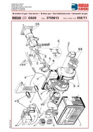
Download Burner Manual - Riello Burners
Download Burner Manual - Riello Burners
Download Burner Manual - Riello Burners

Create successful ePaper yourself
Turn your PDF publications into a flip-book with our unique Google optimized e-Paper software.
Installation, use and maintenance instructionsKerosene burnersOne stage operationCODE MODEL TYPE3514157 RDB2.2 15-21 744T1K3514257 RDB2.2 21-26 744T2K3514557 RDB2.2 26-33 744T5K2903104 (8) - 03/2012
Original instructions
Contents1 Declaration.................................................................................................................................................................................. 32 Information and general warnings............................................................................................................................................ 42.1 Information about the instruction manual........................................................................................................................ 42.1.1 Introduction ..................................................................................................................................................................... 42.1.2 General dangers ............................................................................................................................................................. 42.1.3 Danger: live components ................................................................................................................................................ 42.2 Guarantee and responsibility .......................................................................................................................................... 52.3 Guidance for the use of bio fuel blends up to 30% where gas oil use is permitted by the appliance Manufacturer ....... 52.3.1 Information and general instructions............................................................................................................................... 62.3.2 Product Disclaimer Statement ........................................................................................................................................ 63 Safety and prevention................................................................................................................................................................ 73.1 Introduction ..................................................................................................................................................................... 73.2 Safety warnings .............................................................................................................................................................. 73.3 Basic safety rules............................................................................................................................................................ 73.4 Personnel training........................................................................................................................................................... 74 Technical description of the burner ......................................................................................................................................... 84.1 Technical data ................................................................................................................................................................ 84.2 <strong>Burner</strong> description........................................................................................................................................................... 84.3 <strong>Burner</strong> equipment ........................................................................................................................................................... 84.4 <strong>Burner</strong> dimensions.......................................................................................................................................................... 94.5 Firing rates...................................................................................................................................................................... 95 Installation ................................................................................................................................................................................ 105.1 Notes on safety for the installation................................................................................................................................ 105.2 Handling........................................................................................................................................................................ 105.3 Preliminary checks........................................................................................................................................................ 105.4 Installer/Servicer notes for the use of Gas oil with Bio blends up to 30% where gas oil use is permittedby the appliance Manufacturer ..................................................................................................................................... 115.5 Working position ........................................................................................................................................................... 115.6 Boiler fixing ................................................................................................................................................................... 125.7 <strong>Burner</strong> assembly........................................................................................................................................................... 126 Hydraulic systems.................................................................................................................................................................... 146.1 Fuel supply ................................................................................................................................................................... 146.1.1 Pump ............................................................................................................................................................................ 146.2 One pipe system........................................................................................................................................................... 156.2.1 Priming pump................................................................................................................................................................ 156.3 Two pipe system........................................................................................................................................................... 166.3.1 Priming pump................................................................................................................................................................ 167 Electrical system ...................................................................................................................................................................... 177.1 Notes on safety for the electrical wiring ........................................................................................................................ 177.2 Electrical wiring............................................................................................................................................................. 187.2.1 Control box ................................................................................................................................................................... 188 Start-up, calibration and operation of the burner ................................................................................................................. 198.1 Notes on safety for the first start-up.............................................................................................................................. 198.2 Combustion adjustment ................................................................................................................................................ 198.3 Nozzles installation ....................................................................................................................................................... 198.3.1 Nozzles reccomended .................................................................................................................................................. 198.4 Pump pressure ............................................................................................................................................................. 208.5 Air damper adjustment.................................................................................................................................................. 208.5.1 Only for type 744T1K (for low output)........................................................................................................................... 208.6 Electrodes setting ......................................................................................................................................................... 218.7 <strong>Burner</strong> start-up cycle..................................................................................................................................................... 219 Maintenance.............................................................................................................................................................................. 2231041 GB
Contents9.1 Notes on safety for the maintenance.............................................................................................................................229.2 Maintenance programme ..............................................................................................................................................229.2.1 Maintenance frequency .................................................................................................................................................229.2.2 Checking and cleaning ..................................................................................................................................................2210 Faults / Solutions ......................................................................................................................................................................2331042 GB
Declaration1 DeclarationDeclaration of conformity in accordance with ISO / IEC 17050-1Manufacturer:RIELLO S.p.A.Address: Via Pilade <strong>Riello</strong>, 737045 Legnago (VR)Product:Kerosene and gas oil burnersModel: RDB2.2 15-21RDB2.2 21-26RDB2.2 26-33These products are in compliance with the following Technical Standard:EN 12100EN 267and according to the European Directives:MD 2006/42/EC Machine DirectiveLVD 2006/95/EC Low Voltage DirectiveEMC 2004/108/EC Electromagnetic CompatibilityThe quality is guaranteed by a quality and management system certified in accordance with UNI EN ISO 9001.Legnago, 30.07.2010Mr. G. Conticini<strong>Burner</strong>s Division DepartmentRIELLO S.p.A.Mr. R. Cattaneo31043 GB
Information and general warnings2 Information and general warnings2.1 Information about the instruction manual2.1.1 IntroductionThe instruction manual supplied with the burner: is an integral and essential part of the product and must notbe separated from it; it must therefore be kept carefully forany necessary consultation and must accompany the burnereven if it is transferred to another owner or user, or toanother system. If the manual is lost or damaged, anothercopy must be requested from the Technical AssistanceService of the area; is designed for use by qualified personnel; offers important indications and instructions relating to theinstallation safety, start-up, use and maintenance of theburner.Symbols used in the manualIn some parts of the manual you will see triangular DANGERsigns. Pay great attention to these, as they indicate a situation ofpotential danger.2.1.2 General dangersThe dangers can be of 3 levels, as indicated below.DANGERWARNINGCAUTIONMaximum danger level!This symbol indicates operations which, if not carriedout correctly, cause serious injury, death orlong-term health risks.This symbol indicates operations which, if not carriedout correctly, may cause serious injury, deathor long-term health risks.This symbol indicates operations which, if not carriedout correctly, may cause damage to the machineand/or injury to people.2.1.3 Danger: live componentsDANGEROther symbolsAbbreviations usedCh. ChapterFig. FigurePage PageSec. SectionTab. TableThis symbol indicates operations which, if not carriedout correctly, lead to electric shocks with lethalconsequences.ENVIRONMENTAL PROTECTIONThis symbol gives indications for the use of themachine with respect for the environment.This symbol indicates a list.Delivery of the system and the instruction manualWhen the system is delivered, it is important that: the instruction manual is delivered to the user by the systemmanufacturer, with the recommendation to keep it in theroom where the heat generator is to be installed. The instruction manual shows:– the serial number of the burner;.........................................................................................– the address and telephone number of the nearest AssistanceCentre............................................................................................................................................................................................................................................................................ The system supplier must carefully inform the user about:– the use of the system;– any further tests that may be required before activating thesystem;– maintenance, and the need to have the system checked atleast once a year by a representative of the manufactureror another specialised technician.To ensure a periodic check, the manufacturer recommendsthe drawing up of a Maintenance Contract.31044 GB
Information and general warnings2.2 Guarantee and responsibilityThe manufacturer guarantees its new products from the installationdate, in accordance with the regulations in force and/or thesales contract. At the moment of the first start-up, check that theburner is integral and complete.WARNINGFailure to observe the information given in thismanual, operating negligence, incorrect installationand carrying out of non authorised modificationswill result in the annulment by themanufacturer of the guarantee that it supplies withthe burner.In particular, the rights to the guarantee and the responsibility willno longer be valid, in the event of damage to things or injury topeople, if such damage/injury was due to any of the followingcauses: incorrect installation, start-up, use and maintenance of theburner; improper, incorrect or unreasonable use of the burner; intervention of unqualified personnel; carrying out of unauthorised modifications on the equipment; use of the burner with safety devices that are faulty, incorrectlyapplied and/or not working; installation of untested supplementary components on theburner; powering of the burner with unsuitable fuels; faults in the fuel supply system; continuation of use of the burner when a fault has occured; repairs and/or overhauls incorrectly carried out; modification of the combustion chamber with inserts thatprevent the regular development of the structurally establishedflame; insufficient and inappropriate surveillance and care of thoseburner components most likely to be subject to wear andtear; the use of non-original components, including spare parts,kits, accessories and optional; force majeure.The manufacturer furthermore declines any and every responsibilityfor the failure to observe the contents of thismanual.<strong>Riello</strong> warranty is subject to correct burner, appliance and applicationmatching, and set up in line with <strong>Riello</strong>'s instructions andguidelines. All components within the hydraulic circuit suitable forbio fuel use and supplied by <strong>Riello</strong> will be identified as Bio compatible.No warranty is given in relation to the use of componentswhich are not so identified with bio fuel blends. If in any doubtplease contact <strong>Riello</strong> for further advice.If any <strong>Riello</strong> burners are used with fuel with a bio content >30%then the components within the hydraulic circuit maybe affectedand are not covered under warranty.The hydraulic circuit consists of:– Pump– Hydraulic ram (where applicable)– Valve block– Flexible oil lines (considered as a consumable component)1 Irrespective of any warranty given by <strong>Riello</strong> in relation tonormal use and manufacturing defects, when fuels notmeeting the relevant standards are used, or where fuelstorage issues have not been addressed correctly, or theequipment used is not compatible, if failures occur whichare directly or indirectly attributed to such issues and/or tothe non-observance of this guidance, then no warranty orliability is implied or accepted by <strong>Riello</strong>.2 <strong>Riello</strong> have carefully chosen the specification of the biocompatible components including the flexible oil lines toprotect the pump, safety value and nozzle. The <strong>Riello</strong> warrantyis dependent upon the use of <strong>Riello</strong> genuine componentsincluding the oil lines, being used.3 <strong>Riello</strong> warranty does not cover defects arising from incorrectcommissioning or servicing by non <strong>Riello</strong> employedservice engineers, and any issues impacting the burnerarising from external site related issues.2.3 Guidance for the use of bio fuel blends up to 30% where gas oil use is permitted by the applianceManufacturerBackgroundWith increasing focus on renewable and sustainable energy requirements,Bio fuel usage is set to increase. <strong>Riello</strong> is committedto promoting energy conservation and the use of renewable energyfrom sustainable resources including liquid bio fuels, howeverthere are some technical aspects that must be considered atthe planning stage of using such fuels to reduce the potential forequipment failure or the risks of fuel leakage.Liquid Bio fuel is a generic description used for oil that can comefrom numerous feed stocks including recycled cooking oils.These types of oils have to be considered and treated differentlyfrom standard mineral or fossil fuels, as they are generally moreacidic, hydroscopic and less stable.Due to this, a holistic approach is needed from the specificationof the liquid Bio fuel, the storage of the fuel, its oil supply line andancillary equipment, and very importantly the oil filtration and theburner itself. The specification for FAME (Fatty Acids Methyl Ester)liquid Bio fuel is critical to reliable equipment operation.It is a minimum requirement that the fuel blend (up to 30% Bio) isobtained with gasoil in accordance with the relevant EN standards,regional regulations and FAME in accordance with EN14214. It is also important that the fuel blends meet the requirementsrelated to operational environment conditions within therelevant EN standards.When choosing your <strong>Riello</strong> oil products where you know Bio fuelswill be in use, please make sure that a Bio compatible burner and/or components have been supplied. If an existing burner is to beused with a liquid Bio fuel then a kit may be required to make itcompatible and the guidance notes enclosed concerning oil storageand filtration must be adhered to. The end user is responsiblefor the thorough verification of the potential risks associated withthe introduction of a bio fuel blend and the suitability of the appliancesand installation applicable.Irrespective of any warranty given by <strong>Riello</strong> in relation to normaluse and manufacturing defects, when fuels not meeting the relevantstandards are used, or where fuel storage issues have notbeen addressed correctly, or the equipment used is not compatible,if failures occur which are directly or indirectly attributed tosuch issues and/or to the non-observance of this guidance, thenno warranty or liability is implied or accepted by <strong>Riello</strong>.31045 GB
Information and general warnings2.3.1 Information and general instructionsTo ensure consistency, the supplier of the fuel must be able todemonstrate compliance with a recognised Quality Control andmanagement system to ensure high standards are maintainedwithin the storage, blending and delivery processes.The installation oil storage tank and its ancillaries must also beprepared BEFORE liquid Bio fuel is introduced.Checks and preparation should include: For new installations, make sure that all materials and sealsin the oil storage and supply line to the burner are compatiblewith Bio fuels. For all installations, there must be a goodquality bio compatible oil filter at the tank and then a secondaryfilter of 60 Microns protecting the burner from contamination. If an existing oil storage tank is to be used then in additionto the materials checks as detailed above, it will be essentialthat the tank is first inspected for condition and checkedfor water or other contamination. <strong>Riello</strong> strongly recommendsthat the tank is cleaned and oil filters replaced priorto Bio fuel delivery. If this is not completed then due to thehydroscopic nature of Bio fuel, it will effectively clean thetank, absorb water present which in turn will result in equipmentfailure that is not covered by the manufacturer's warranty. Depending on the capacity of the oil storage tank and oilusage, fuels may remain static within the tank for some considerabletime and so <strong>Riello</strong> recommends that the oil distributoris consulted regarding the use of additional Biocideswithin the fuel to prevent microbial growth from occurringwithin the tank. <strong>Riello</strong> suggests that fuel suppliers and orservice companies are contacted for guidance on fuel filtration.Special attention should be applied to duel fuel applicationswhere oil may be stored for long periods of time. The burner must be set according to the appliance applicationand commissioned checking that all combustion parametersare as recommended in the appliance technicalmanual. <strong>Riello</strong> recommends that the in line and burner oil pump filtersare inspected and if required replaced at least every 4months during burner use, before the burner start-up followinga long period of discontinue operation and even morefrequently where contamination has occurred. Particularattention is needed when inspecting and checking for fuelleakages from seals, gaskets and hoses.2.3.2 Product Disclaimer StatementCAREFULLY READ THE FOLLOWING DISCLAIMER. YOUACCEPT AND AGREE TO BE BOUND BY THIS DISCLAIMERBY PURCHASING RIELLO BIO COMPATIBLE BURNERSAND/OR COMPONENTS.Although the information and recommendations (hereinafter “Information”)in this guidance is presented in good faith, believed tobe correct and has been carefully checked, <strong>Riello</strong> (and its subsidiaries)makes no representations or warranties as to the completenessor accuracy of the Information. Information is suppliedupon the condition that the persons receiving same will maketheir own determination as to its suitability for their purposes priorto use. In no event will <strong>Riello</strong> (and its subsidiaries) be responsiblefor damages of any nature whatsoever resulting from the use ofor reliance upon Information.Other than set forth herein, <strong>Riello</strong> (and its subsidiaries) makes noadditional warranties with respect to the bio compatible burner,either express or implied, including that of merchantability or fitnessfor a particular purpose or use.In no event shall <strong>Riello</strong> (and its subsidiaries) be liable for any indirect,incidental, special or consequential damages including,without limitation, loss of profits, damages for loss of businessprofits, business interruption, loss of business information, loss ofequipment, or other pecuniary loss or compensation for serviceswhether or not it is advised of the possibility of such damages.With the exception of injuries to persons, <strong>Riello</strong>'s liability is limitedto the customer's right to return defective/non-conforming productsas provided by the relevant product warranty.31046 GB
Safety and prevention3 Safety and prevention3.1 IntroductionThe burners have been designed and built in compliance withcurrent regulations and directives, applying the known technicalrules of safety and envisaging all the potential danger situations.It is necessary, however, to bear in mind that the imprudent andclumsy use of the equipment may lead to situations of death riskfor the user or third parties, as well as the damaging of the burneror other items. Inattention, thoughtlessness and excessive confidenceoften cause accidents; the same applies to tiredness andsleepiness.It is a good idea to remember the following: The burner must only be used as expressly described. Anyother use should be considered improper and therefore dangerous.In particular:it can be applied to boilers operating with water, steam, diathermicoil, and to other uses expressly named by the manufacturer;the type and pressure of the fuel, the voltage and frequency of theelectrical power supply, the minimum and maximum deliveries forwhich the burner has been regulated, the pressurisation of thecombustion chamber, the dimensions of the combustion chamberand the room temperature must all be within the values indicatedin the instruction manual. Modification of the burner to alter its performance and destinationsis not allowed. The burner must be used in exemplary technical safety conditions.Any disturbances that could compromise safety mustbe quickly eliminated. Opening or tampering with the burner components is notallowed, apart from the parts requiring maintenance. only those parts detailed as available as spare parts by themanufacturer can be replaced.3.2 Safety warningsThe dimension of the boiler’s combustion chamber must respondto specific values, in order to guarantee a combustion with thelowest polluting emissions rate.The Technical Service Personnel will be glad to give you all theimformation for a correct matching of this burner to the boiler.This burner must only be used for the application it was designedfor.The manufacturer accepts no liability within or without the contractfor any damage caused to people, animals and property dueto installation, adjustment and maintenance errors or to improperuse.3.3 Basic safety rulesChildren or inexpert persons must not use the appliance.Under no circumstances must the intake grids, dissipationgrids and ventilation vents in the installation room be coveredup with cloths, paper or any other material.Unauthorised persons must not attempt to repair the appliance.It is dangerous to pull or twist the electric leads.Cleaning operations must not be performed if the applianceis not disconnected from the main power supply.Do not clean the burner or its parts with inflammable substances(e.g. petrol, alcohol, etc.). The cover must becleaned with soapy water.Do not place anything on the burner.Do not block or reduce the size of the ventilation vents inthe installation room.Do not leave containers and inflammable products or combustiblematerials in the installation room.3.4 Personnel trainingThe user is the person, body or company that has acquired themachine and intends to use it for the specific purpose. He is responsiblefor the machine and for the training of the people workingaround it.The user: undertakes to entrust the machine exclusively to suitablytrained and qualified personnel; must take all the measures necessary to prevent unauthorisedpeople gaining access to the machine; undertakes to inform his personnel in a suitable way aboutthe application and observance of the safety instructions.With that aim, he undertakes to ensure that everyone knowsthe use and safety instructions for his own duties; must inform the manufacturer if faults or malfunctioning ofthe accident prevention systems are noticed, along with anypresumed danger situation. Personnel must always use the personal protective equipmentenvisaged by legislation and follow the indicationsgiven in this manual. Personnel must observe all the danger and caution indicationsshown on the machine. Personnel must not carry out, on their own initiative, operationsor interventions that are not within their province. Personnel must inform their superiors of every problem ordangerous situation that may arise. The assembly of parts of other makes, or any modifications,can alter the characteristics of the machine and hence compromiseoperating safety. The manufacturer thereforedeclines any and every responsibility for any damage thatmay be caused by the use of non-original parts.31047 GB
Technical description of the burner4 Technical description of the burner4.1 Technical dataType 744T1K 744T2K 744T5KOutput - Thermal power(with air at 20 °C)1.2 - 2.2 kg/h14.3 - 26.3 kW1.6 - 2.8 kg/h19.2 - 33.5 kW2.8 - 4.5 kg/h33.5 - 54 kWFuel Kerosene, viscosity 1.6 – 6 mm 2 /s at 20 °C (Hi = 11.97 kWh/kg)Electrical supply Single phase, ~ 50Hz 230 V ± 30%MotorRun current 0.85 A – 2700 rpm – 283 rad/sCapacitor4.5 FIgnition transformerSecondary 8 kV – 25 APumpKerosene, maximum pressure 10 bar (145 psi)Absorbed electrical power0.16 kWTab. A4.2 <strong>Burner</strong> description3826975411 Kerosene pump2 Control box3 Reset button with lock-out lamp4 Flange with insulating gasket5 Air damper adjustment screwD61156 Pump pressure adjustment screw7 Pressure gauge port8 Photoresistance9 Blast tubeFig. 14.3 <strong>Burner</strong> equipmentFlange with insulating gasket.............................................. No. 1Screws and nuts for flange to be fixed to boiler .................. No. 4Screw and nuts for flange ................................................... No. 1Hoses with nipples .............................................................. No. 1Screw of by-pass pump....................................................... No. 1Hexagonal key .................................................................... No. 1Screw and terminal screw for feeding cable ....................... No. 3WARNINGThe hoses supplied with this burner set forKerosene use are not suitable for use with Gas oilcontaining a Bio blend.Please refer to the spare part list for the specifichoses suitable for bio fuel use.In case of use with gas oil containing up to 30%Bio blend, it will be essential to use flexible oillines suitable for bio fuel use.Please contact <strong>Riello</strong> for further information.31048 GB
Technical description of the burner4.4 <strong>Burner</strong> dimensionsFlange<strong>Burner</strong>180136 15050 20745°45°1172 72225170ø 8513015020D6114Fig. 24.5 Firing ratesThe MAXIMUM OUTPUT is chosen from within the diagram area(Fig. 3).The MINIMUM OUTPUT must not be lower than the minimumlimit of the diagram.The burner delivery must be selected within area of the diagrams(Fig. 3). This area is called firing rates and provides the maximumdelivery of the burner in relation to the pressure in the combustionchamber.The work point may be found by plotting a vertical line from thedesired delivery and a horizontal line from the pressure in thecombustion chamber. The intersection of these two lines is thework point which must lie within the firing rates.WARNINGThe firing rate area values have been obtainedconsidering a surrounding temperature of 20 °C,and an atmospheric pressure of 1013 mbar (approx.0 m above sea level) and with the combustionhead adjusted as shown on page 19.D7101432744T1K744T2K744T5K101214161820 22 24 26 28 30 32 34 36 38 4042 44 46 4850 52 5456kW1.21.52 2.533.544.5kg/hFig. 331049 GB
Installation5 Installation5.1 Notes on safety for the installationAfter carefully cleaning all around the area where the burner willbe installed, and arranging the correct lighting of the environment,proceed with the installation operations.DANGERAll the installation, maintenance and disassemblyoperations must be carried out with the electricitysupply disconnected.WARNINGThe installation of the burner must be carried outby qualified personnel, as indicated in this manualand in compliance with the standards and regulationsof the laws in force.5.2 HandlingThe packaging of the burner includes a carton box, so it is possibleto move the burner (still packaged) with a transpallet truck orfork lift truck.WARNINGThe handling operations for the burner can behighly dangerous if not carried out with the greatestattention: keep any unauthorised people at adistance; check the integrity and suitableness ofthe available means of handling.Check also that the area in which you are workingis empty and that there is an adequate escapearea (i.e. a free, safe area to which you can quicklymove if the burner should fall).When handling, keep the load at not more than20-25 cm from the ground.CAUTIONAfter positioning the burner near the installationpoint, correctly dispose of all residual packaging,separating the various types of material.Before proceeding with the installation operations,carefully clean all around the area where the burnerwill be installed.5.3 Preliminary checksChecking the consignmentCAUTIONAfter removing all the packaging, check the integrityof the contents. In the event of doubt, do notuse the burner; contact the supplier.The packaging elements (wooden cage or cardboardbox, nails, clips, plastic bags, etc.) must notbe abandoned as they are potential sources ofdanger and pollution; they should be collected anddisposed of in the appropriate places.Checking the characteristics of the burnerWARNINGWARNINGThe output of the burner must be within theboiler's firing rate;A burner label that has been tampered with, removedor is missing, along with anything else thatprevents the definite identification of the burnermakes any installation or maintenance work difficult.D9370Fig. 4Check the identification label of the burner, showing: the model A)(Fig. 4) and type of burner B); the year of manufacture, in cryptographic form C); the serial number D); the electrical input power E); the types of fuel used and the relative supply pressures F); the data of the burner's minimum and maximum output possibilitiesG)(see Firing rate)310410 GB
Installation5.4 Installer/Servicer notes for the use of Gas oil with Bio blends up to 30% where gas oil use is permitted bythe appliance ManufacturerDuring the burner installation, check that the gasoil and biofuel blends are in accordance with <strong>Riello</strong> specifications(please refer to the chapters "Technical Data" and "Guidancefor the use of bio fuel blends up to 30%" within theburner technical manual).If a Bio blend is in use the installer must seek informationfrom the end user that their fuel supplier can evidence thatthe blends of fuel conform to the relevant standards.Check that the materials used in the construction of the oiltank and ancillary equipment are suitable for bio fuels, If notthese must be upgraded or replaced with Bio compatibleparts.Particular attention should be given to the oil storage tankand supply to the burner. <strong>Riello</strong> recommends that existingoil storage tanks are cleaned, inspected and any traces ofwater are removed BEFORE bio fuel is introduced (Contactthe tank manufacturer or oil supplier for further advice). Ifthese recommendations are not respected this will increasethe risk of contamination and possible equipment failure.In line oil filters should be replaced making sure that theyare Bio compatible. <strong>Riello</strong> recommends a good quality biocompatible oil filter at the tank and a secondary 60 micronfilter are used to protect the burner pump and nozzle fromcontamination.The burner hydraulic components and flexible oil lines mustbe suitable for bio fuel use (check with <strong>Riello</strong> if in doubt).<strong>Riello</strong> have carefully chosen the specification of the biocompatible components including the flexible oil lines toprotect the pump, safety value and nozzle. The <strong>Riello</strong> warrantyis dependent upon the use of <strong>Riello</strong> genuine componentsincluding the oil lines, being used. The burner mustbe commissioned and combustion parameters set to appliancemanufacturer's recommendations.Regularly check visually for any signs of oil leakage fromseals, gaskets and hoses.It is strongly recommended that with Bio fuel use, oil filtersare inspected and replaced every 4 months. More regularlywhere contamination is experienced.During extended periods of non operation and/or whereburners are using oil as a standby fuel, it is strongly recommendedthat the burner is put into operation for shorts periodsat least every three months.5.5 Working positionWARNINGThe burner is designed to operate only in the positions1, and 3 (Fig. 5).Installation 1 is preferable, as it is the only one thatallows performing maintenance operations as describedin this manual. Installations 2, 3 and 4 allowworking operations but not maintenance withhooking to the boiler.DANGERAny other position could compromise the correctoperation of the appliance. Installation 5 is forbiddenfor safety reasons.1 2 3 4 5D4618Fig. 5310411 GB
Installation5.6 Boiler fixing1 Put on the flange 1)(Fig. 6) the screw and two nuts. Fix the flange 1)(Fig. 7) to the boiler door 4) using screws 2)and (if necessary) the nuts 3) interposing the insulating gasket5).WARNINGThe seal between burner and boiler must beairtight.E9095Fig. 6531E909442Fig. 75.7 <strong>Burner</strong> assemblyCF ApplicationIn case of CF applications, the burner shall not operate withoutprotection (A) of the suction inlet.AWARNINGFor correct BF application, the burner must be installedon an appropriate BF boiler.In case of BF applications an optional snorkel and gasket areavailable replacing (A) with (B).This item can be supplied separately.D5884Fig. 8BBF ApplicationCAUTIONThe temperature of the incoming air must notexceed 70 °C.D5883Fig. 9310412 GB
InstallationThe combustion air supply is through a flexible or rigid pipe connectedto the air intake.Consequently, you must comply with the following requirementsand instructions:The combustion air intake tube must be:- fastened securely to the burner;- made of a suitable material, with temperature characteristicsin the range - 30 °C to 80 °C;- in compliance with all requirements of applicable regulationsin force in the country of destination.The intake-tube / burner system must not allow a loss ofover 2 m 3 /h at 0.5 mbar:for instance, the above requirements will be met if you use fluesfor pressure exhaust of flue gases (the condensation kind). Make sure the air intake tube’s inlet is positioned so that it isnot likely to be obstructed by foreign matter and, where necessary,use suitable screens. The inside diameter of the hose must be at least 80 mm. The intake tube can be up to 6 metres in length.WARNINGLength is reduced if there are bends in the intakesection.For instance, using a tube with a smooth insidesurface, you must allow for the following losses:– for each 45° bend, tube length is reduced by0.5 m;– for each 90° bend, tube length is reduced by0.8 m.NOTE:<strong>Burner</strong> installation must comply with one of the installationsillustrated in the figures below.WARNINGUnder no circumstances should the air’sentry in the hose intake area be obstructed.The hose must not be blocked in any way orfeature a shutting device (valves, membranesetc.).Coaxial tubes must not be installed for anyreason.S7851Fig. 10S7876Fig. 11S7853Fig. 12310413 GB
Hydraulic systems6 Hydraulic systems6.1 Fuel supply6.1.1 PumpThe pump is designed to allow working with one pipe.In order to obtain two pipes working it is necessary to unscrew thereturn plug 2)(Fig. 13), screw the by-pass screw 3),supplied asburner equipment and then screw the return hose.7WARNINGWhere gas oil containing bio diesel is in use, it isrecommended to avoid over oxygenation of theblended fuels.Where at all possible avoid the use of two pipesystems where the circulated fuel is returned tothe tank.If this cannot be avoided make sure that the returnpipe is normally below the surface of the fuel levelwithin the storage tank. See Fig. 16.86543WARNINGWARNINGThe suction plug 1) is made of plastic. Once removed,it must not be used again.In single pipe installations, the plug in the returnline 2) must be totally in steel.In case of use with gas oil containing up to 30%Bio blend, it will be essential to use flexible oillines suitable for bio fuel use.Please contact <strong>Riello</strong> for further information.1D109342Fig. 13Key (Fig. 13)1 Suction line2 Return line3 By-pass screw4 Gauge connection5 Pressure adjuster6 Vacuum gauge connection7 Valve8 Auxiliary pressure test point310414 GB
Hydraulic systems6.2 One pipe systemPressurised one pipe systems (Fig. 14) have a positive fuel pressureon intake to the burner.Usually the tank is higher than the burner, or the fuel pumpingsystems are on the outside of the boiler.Vacuum one pipe systems (Fig. 15) have a negative fuel pressure(depression) on intake to the burner.Usually the tank is lower than the burner.CAUTIONYou are advised to use additional filters on the fuelsupply line.<strong>Riello</strong> recommends a good quality fuel filter at thetank (Fig. 14 - Fig. 15) and a secondary filter (60 for gas oil and 15 for kerosene) are used to protectthe burner pump and nozzle from contamination.In case of Biodiesel use, pay attention to installBiocompatible filters.HHmax. 4 m6.2.1 Priming pumpOn the system in Fig. 14 it is sufficient to loosen the plug of thevacuum gauge 6)(Fig. 13) and wait until the fuel flows out.On the system in Fig. 15 start the burner and wait for the priming.Should lock-out occur prior to the arrival of the fuel, await at least20 seconds before repeating the operation.WARNINGThe installer must ensure that the supply pressureis not above 0.5 bar.Above that level, the pump seal is subject to toomuch stress.min. 0.1 mHmax. 4 mHmetresI.D. (8 mm)D11010H difference of levelL max. lenght of the suction lineI.D. interminal diameter of the oil pipesL metresI.D. (10 mm)0 35 1000.5 30 1001 25 1001.5 20 902 15 703 8 303.5 6 20Fig. 15Tab. CNOTE:The Tab. B and Tab. C show the maximum approximate lengthsfor the supply line, depending on the difference in level, length,and the diameter of the fuel conduit.D11009HmetresI.D. (8 mm)L metresI.D. (10 mm)0.5 10 201 20 401.5 40 802 60 100Fig. 14Tab. B310415 GB
Hydraulic systems6.3 Two pipe systemVacuum two pipe systems (Fig. 16) have a negative fuel pressure(depression) on intake to the burner.Usually the tank is lower than the burner.The return line should terminate in the oil tank at the same levelas the suction line; in this case a non-return valve is not required.Should however the return line arrives over the fuel level, thenon-return valve is indispensable. This solution however is lesssafe than previous one, due to the possibility of leakage of thevalve.CAUTION6.3.1 Priming pumpWARNINGOn the system in Fig. 16 start the burner and wait for the priming.Should lock-out occur prior to the arrival of the fuel, await at least20 seconds before repeating the operation.WARNINGYou are advised to use additional filters on the fuelsupply line.<strong>Riello</strong> recommends a good quality fuel filter at thetank (Fig. 16) and a secondary filter (60 for gasoil and 15 for kerosene) are used to protect theburner pump and nozzle from contamination.In case of Biodiesel use, pay attention to installBiocompatible filters.Before starting the burner make sure that the returnpipe-line is not clogged: any obstructionwould cause the pump seals to break.The pump vacuum should not exceed a maximumof 0.4 bar (30 cm Hg).Beyond this limit gas is released from the oil.HHmetresD10011H max. 4 mI.D. (8 mm)H difference of levelL max. lenght of the suction lineI.D. interminal diameter of the oil pipesL metresI.D. (10 mm)0 35 1000.5 30 1001 25 1001.5 20 902 15 703 8 303.5 6 20Fig. 16Tab. DNOTE:The Tab. D shows the maximum approximate lengths for the supplyline, depending on the difference in level, length, and the diameterof the fuel conduit.310416 GB
Electrical system7 Electrical system7.1 Notes on safety for the electrical wiringDANGERThe electrical wiring must be carried out with the electrical supply disconnected.Electrical wiring must be carried out by qualified personnel and in compliance with the regulations currently inforce in the country of destination. Refer to the wiring diagrams.The manufacturer declines all responsibility for modifications or connections different from those shown in thewiring diagrams.Do not invert the neutral with the phase in the electrical supply line. Any inversion would cause a lockout due tofiring failure.Check that the electrical supply of the burner corresponds to that shown on the identification label and in thismanual.The burners have been set for intermittent operation. This means they should compulsorily be stopped at leastonce every 24 hours to enable the control box to perform checks of its own start-up efficiency. Normally theboiler's thermostat/pressure switch ensures the stopping of the burner.If this is not the case, it is necessary to apply in series with IN a timer switch that turns off the burner at least onceevery twenty-four hours. Refer to the wiring diagrams.The electrical safety of the device is obtained only when it is correctly connected to an efficient earthing system,made according to current standards. It is necessary to check this fundamental safety requirement. In the eventof doubt, have the electrical system checked by qualified personnel.The electrical system must be suitable for the maximum input power of the device, as indicated on the label andin the manual, checking in particular that the section of the cables is suitable for the input power of the device.For the main power supply of the device from the electricity mains:- do not use adapters, multiple sockets or extensions;- use an omnipolar switch, as indicated by the current safety standards.Do not touch the device with wet or damp body parts and/or in bare feet.Do not pull the electric cables.Before carrying out any maintenance, cleaning or checking operations:DANGERdisconnect the electrical supply from the burner bymeans of the main system switch;DANGERisolate the fuel supplyIf the cover is still present, remove it and proceed with the electricalwiring according to the wiring diagrams.Use flexible cables in compliance with the EN 60 335-1 standard.310417 GB
Electrical system7.2 Electrical wiring~ 50Hz - 230VPE N LMain switchT6ASafetythermostatLimitthermostatCONTROL BOX535SE/LDRemote lock-out signal(230V - 0.5A max.)Ignitionelectrodes7.2.1 Control boxDANGERTo remove the control box (Fig. 18) from the burner follow of theistruction: Loosen the screw 1), open the protection 2) and remove allcomponents. Remove the coil 3). Loosen the two screws 4). Move a little the control box and remove the high voltageleads.4This operation must be performed with the burnerturned off and mains power disconnected.21Photoresistance<strong>Burner</strong>-earthOil valve3BlueWhiteBlackMotor4E9153Fig. 18D4240CapacitorFig. 17WARNINGDo not swap neutral and phase over, followthe diagram shown carefully and carry out agood earth connection.The electrical wiring carried out by theinstaller must be in compliance with the rulesin force in the country.The section of the conductors must be atleast 1mm 2 . (Unless requested otherwise bylocal standards and legislation).TESTING:Check the shut-down of the burner by opening the thermostatsand the lock-out by darkening the photoresistance.310418 GB
Start-up, calibration and operation of the burner8 Start-up, calibration and operation of the burner8.1 Notes on safety for the first start-upWARNINGThe first start-up of the burner must be carried outby qualified personnel, as indicated in this manualand in compliance with the standards and regulationsof the laws in force.WARNINGCheck the correct working of the adjustment, commandand safety devices.8.2 Combustion adjustmentIn conformity with Efficiency Directive 92/42/EEC the applicationof the burner on the boiler, adjustment and testing must be carriedout observing the instruction manual of the boiler, includingverification of the CO and CO 2 concentration in the flue gases,their temperatures and the average temperature of the water inthe boiler.WARNINGCombustion air is drawn in from outside, meaningthere may be notable changes in temperature,which can affect the percentage of CO 2 .You are advised to adjust CO 2 in accordance withthe graph featured.Exemple: outside air temperature 10 °C, adjustCO 2 to 11.6% (± 0.2%).% CO2D7052Outside air temperature (°C)Fig. 198.3 Nozzles installationThe burner complies with the emission requirements of theEN 267 standard.In order to guarantee that emissions do not vary, recommendedand/or alternative nozzles specified by the manufacturer in the Instructionand warning booklet should be used.It is advisable to replace nozzles every year duringregular maintenance operations.WARNINGCAUTIONThe use of nozzles other than those specified bythe manufacturer and inadequate regularmaintenance may result into emission limits nonconformingto the values set forth by theregulations in force, and in extremely seriouscases, into potential hazards to people andobjects.The manufacturing company shall not be liable forany such damage arising from nonobservance ofthe requirements contained in this manual.8.3.1 Nozzles reccomended Delavan type A - W; Steinen type Q - S; Danfoss type H - S - EH - ES.Angle 60°: in most cases.Angle 80°: in case of flame detachment, during ignitions at lowtemperatures.310419 GB
Start-up, calibration and operation of the burner8.4 Pump pressureThe pump leaves the factory set for kerosene working.10 bar: maximum pressure for kerosene.8.5 Air damper adjustmentThe air damper is set in factory. This regulation is purely indicative.Each installation however, has its own unpredictable workingconditions: actual nozzle output; positive or negative pressure inthe combustion-chamber, the need of excess air, etc.All these conditions may require a different air damper setting.Secondary air damper (B) - Fig. 21The purpose of this damper is to perform a fine-tuning of the inletair.Tuning of this device is possible acting of the screw (3).8.5.1 Only for type 744T1K (for low output)The air setting is performed by mean of two independent dampers(see Fig. 20 and Fig. 21).Main air damper (A) - Fig. 20The main air damper can be set in either of two positions. To setthe positions of the damper, proceed as follows: Remove the secondary air damper (B) loosing the screws(1). Loosen the screw (2) and rotate the main air damper (A) tothe required position. Retighten the screw (2) and put back the secondary airdamper (B).3 BE9172 Fig. 21BE9281A21Fig. 20310420 GB
Start-up, calibration and operation of the burner8.6 Electrodes settingWARNINGThe position of the electrodes cannot be regulated.In case of failure, check that the measurementsas shown on the figure are respected.Before removing or assembling the nozzle, loosen the screw (A,Fig. 22) and move the electrodes ahead.4 ± 0.3 mmD5230A2 - 2.5 mmFig. 228.7 <strong>Burner</strong> start-up cycleThermostatMotorIgnition transformerValveFlameLock-out lampNormalLock-out due to failure to light~ 12s ~ 12s ~ 5sD5229Fig. 23Lock out is indicated by a lamp on the control box (3, Fig. 1 topage 8)310421 GB
Maintenance9 Maintenance9.1 Notes on safety for the maintenanceThe periodic maintenance is essential for the good operation,safety, yield and duration of the burner.It allows you to reduce consumption and polluting emissions andto keep the product in a reliable state over time.DANGERThe maintenance interventions and the calibrationof the burner must only be carried out by qualified,authorised personnel, in accordance with the contentsof this manual and in compliance with thestandards and regulations of current laws.Before carrying out any maintenance, cleaning or checking operations:DANGERDANGERdisconnect the electricity supply from the burnerby means of the main switch of the system;isolate the fuel supply.9.2 Maintenance programme9.2.1 Maintenance frequencyThe combustion system should be checked at least once ayear by a representative of the manufacturer or anotherspecialised technician.9.2.2 Checking and cleaningCombustion headOpen the burner and make sure that all components of thecombustion head are in good condition, not deformed by thehigh temperatures, free of impurities from the surroundingsand correctly positioned.Clean the combustion head in the fuel exit area, on the diffuserdisc.<strong>Burner</strong>Check for excess wear or loose screws and clean the outside ofthe burner.FanCheck to make sure that no dust has accumulated inside the fanor on its blades, as this condition will cause a reduction in the airflow rate and provoke polluting combustion.PhotoresistanceClean the photoresistance.ElectrodesCheck the correct position of electrodesNozzlesIt is advisable to replace nozzles every year during regularmaintenance operations.Do not clean the nozzle openings; do not even open them.FiltersCheck the filtering baskets on line and at nozzle present in thesystem. Clean or replace if necessary.If rust or other impurities are observed inside the pump, use aseparate pump to lift any water and other impurities that mayhave deposited on the bottom of the tank.PumpPlease check that the supply line and filters are clear. The use ofa pump vacuum gauge will assist in this. This measure permitsthe cause of the anomaly to be traced to either the suction line orthe pump.If the problem lies in the suction line, check to make sure that thefilter is clean and that air is not entering the piping.Hoses Check periodically the flexible pipes conditions. They haveto be replaced at least every 2 years. In case of use of gas oil and bio fuel blends, it is stronglyrecommended to inspect even more frequently the hosesand replace them where contamination has occurred. Check to make sure that the hoses are still in good condition.WARNINGThe hoses supplied with this burner set forKerosene use are not suitable for use with Gas oilcontaining a Bio blend.Please refer to the spare part list for the specifichoses suitable for bio fuel use.In case of use with gas oil containing up to 30%Bio blend, it will be essential to use flexible oillines suitable for bio fuel use.Please contact <strong>Riello</strong> for further information.Fuel tankIf water or contamination is present within the fuel tank, it is essentialthat this is removed before the equipment is to be used.This is extremely important when gas oil containing Bio diesel isin use. If in doubt about how to achieve this then please contactthe fuel or oil tank supplier.BoilerClean the boiler as indicated in the appliance accompanying instructionsin order to maintain all the original combustion characteristicsintact, especially the flue gas temperature andcombustion chamber pressure.CombustionIn case the combustion values found at the beginning of the interventiondo not respect the standards in force or, in any case, donot correspond to a proper combustion, contact the TechnicalAssistant and have him carry out the necessary adjustments.Allow the burner to work for 10 min. and then check thecombustion readings with the parameters indicated within theappliance instruction manual. Then carry out a combustioncheck verifying:– Smoke temperature at the chimney;– Content of CO 2 (%);– Content of CO (ppm);– Smoke value according to opacity smokes index according toBacharach scale.310422 GB
Faults / Solutions10 Faults / SolutionsHere below you can find some causes and the possible solutionsfor some problems that could cause a failure to start or incorrectoperation of the burner.A fault usually makes the lock-out lamp light which is situatedinside the reset button of the control box (3, Fig. 1 to page 8).When lock out lamp lights the burner will attempt to light only afterpushing the reset button. After this if the burner functions correctly,the lock-out can be attributed to a temporary fault.If however the lock out continues the cause must be determinedand the solution found.FAULTS POSSIBLE CAUSES SOLUTIONThe burner will not startwhen the limit thermostatcloses.<strong>Burner</strong> runs normally in theprepurge and ignition cycleand locks out after 5 secondsca.<strong>Burner</strong> starts with an ignitiondelay.Lack of electrical supply.The photoresistance sees false light.The connections in the control box arewrongly inserted.The photoresistance is dirty.The photoresistance is defective.Flame moves away or fails.The ignition electrodes are wrongly positioned.Air output is too high.Nozzle dirty or worn.Check presence of voltage in the L - N clamps ofthe control box.Check the conditions of the fuses.Check that safety thermostat limit is not lock out.Eliminate the light.Check and connect completely all the plugs.Clean it.Change it.Check pressure and output of the fuel.Check air output.Change nozzle.Check the coil of solenoid valve.Adjust them according to the instructions of thismanual.Set the air output.Replace it.WARNINGThe manufacturer cannot accept responsibility forany damage to persons, animals or property dueto error in installation or in the burner adjustment,or due to improper or unreasonable use or nonobservance of the technical instruction enclosedwith the burner, or due to the intervention of unqualifiedpersonnel.310423 GB
RIELLO S.p.A.I-37045 Legnago (VR)Tel.: +39.0442.630111http:// www.riello.ithttp:// www.rielloburners.comSubject to modifications