Understanding and Using Cyclic Redundancy Checks ... - ZMiTAC
Understanding and Using Cyclic Redundancy Checks ... - ZMiTAC
Understanding and Using Cyclic Redundancy Checks ... - ZMiTAC

Create successful ePaper yourself
Turn your PDF publications into a flip-book with our unique Google optimized e-Paper software.
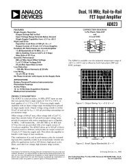
www.dalsemi.comApplication Note 27<strong>Underst<strong>and</strong>ing</strong> <strong>and</strong> <strong>Using</strong> <strong>Cyclic</strong> <strong>Redundancy</strong> <strong>Checks</strong>with Dallas Semiconductor iButton TM ProductsINTRODUCTIONThe Dallas Semiconductor iButton products are a family of devices that all communicate over a singlewire following a specific comm<strong>and</strong> sequence referred to as the 1-Wire TM Protocol. A key feature of eachdevice is a unique 8-byte ROM code written into each part at the time of manufacture. The components ofthis 8-byte code can be seen in Figure 1. The least significant byte contains a family code that identifiesthe type of iButton product. For example, the DS1990A has a family code of 01 Hex <strong>and</strong> the DS1991 hasa family code of 02 Hex. Since multiple devices of the same or different family types can reside on thesame 1-Wire bus simultaneously, it is important for the host to be able to determine how to properlyaccess each of the devices that it locates on the 1-Wire bus. The family code provides this information.The next 6 bytes contain a unique serial number that allows multiple devices within the same family codeto be distinguished from each other. This unique serial number can be thought of as an “address” for eachdevice on the 1-Wire bus. The entire collection of devices plus the host form a type of miniature localarea network, or MicroLAN; they all communicate over the single common wire. The most significantbyte in the ROM code of each device contains a <strong>Cyclic</strong> <strong>Redundancy</strong> Check (CRC) value based on theprevious 7 bytes of data for that part. When the host system begins communication with a device, the 8-byte ROM is read, LSB first. If the CRC that is calculated by the host agrees with the CRC contained inbyte 7 of ROM data, the communication can be considered valid. If this is not the case, an error hasoccurred <strong>and</strong> the ROM code should be read again.Some of the iButton products have up to 8 kbytes of RAM in addition to the 8 bytes of ROM that can beaccessed by the host system with appropriate comm<strong>and</strong>s. Even if iButtons do not have CRC hardwareonboard, if the host has the capability to calculate a CRC value for the ROM codes, then a procedure tostore <strong>and</strong> retrieve data in the RAM portion of the devices using CRCs can also be developed. Data can bewritten to the device in the normal manner; then a CRC value that has been calculated by the host isappended <strong>and</strong> stored with the data. When this data is retrieved from the iButton, the process is reversed.The host compares the CRC value that was computed for the data bytes to the value stored in memory asthe CRC for that data. If the values are equal, the data read from the iButton can be considered valid. Inorder to take advantage of the power of CRCs to validate the serial communication on the 1-Wire bus, anunderst<strong>and</strong>ing of what a CRC is <strong>and</strong> how they work is necessary. In addition, a practical method forcalculation of the CRC values by the host will be required for either a hardware or softwareimplementation.1 of 16 110899
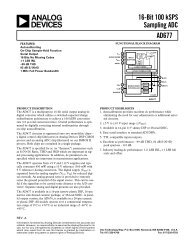
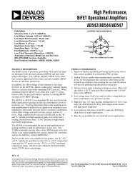
APPLICATION NOTE 27exclusive-or gates in Figure 2, or the presence of coefficients in the polynomial expression, determine theproperties of the CRC <strong>and</strong> the ability of the algorithm to locate certain types of errors in the data. For theDOW CRC, the types of errors that are detectable are:1. Any odd number of errors anywhere within the 64-bit number.2. All double-bit errors anywhere within the 64-bit number.3. Any cluster of errors that can be contained within an 8-bit “window” (1-8 bits incorrect).4. Most larger clusters of errors.The input data is exclusive-or’d with the output of the eighth stage of the shift register in Figure 2. Theshift register may be considered mathematically as a dividing circuit. The input data is the dividend, <strong>and</strong>the shift register with feedback acts as a divisor. The resulting quotient is discarded, <strong>and</strong> the remainder isthe CRC value for that particular stream of input data, which resides in the shift register after the last databit has been shifted in. From the shift register implementation it is obvious that the final result (CRCvalue) is dependent, in a very complex way, on the past history of the bits presented. Therefore, it wouldtake an extremely rare combination of errors to escape detection by this method.The example in Figure 3 calculates the CRC value after each data bit is presented. The shift registercircuit is always reset to 0s at the start of the calculation. The computation begins with the LSB of the 64-bit ROM, which is the 02 Hex family code in this example. After all 56 data bits (serial number + familycode) are input, the value that is contained in the shift register is A2 Hex, which is the DOW CRC valuefor that input stream. If the CRC value which has been calculated (A2 Hex in this example) is now usedas input to the shift register for the next 8 bits of data, the final result in the shift register after the entire64 bits of data have been entered should be all 0s. This property is always true for the DOW CRCalgorithm. If any 8-bit value that appears in the shift register is also used as the next 8 bits in the inputstream, then the result that appears in the shift register after the 8 th data bit has been shifted in is always00 Hex. This can be explained by observing that the contents of the 8 th stage of the shift register is alwaysequal to the incoming data bit, making the output of the EXOR gate controlling the feedback <strong>and</strong> the nextstate value of the first stage of the shift register always equal to a logic 0. This causes the shift register tosimply shift in 0s from left to right as each data bit is presented, until the entire register is filled with 0safter the 8 th bit. The structure of the Dallas Semiconductor 1-Wire 64-bit ROM uses this property tosimplify the hardware design of a device used to read the ROM. The shift register in the host is cleared<strong>and</strong> then the 64 ROM bits are read, including the CRC value. If a correct read has occurred, the shiftregister is again all 0s, which is an easy condition to detect. If a non-0 value remains in the shift register,the read operation must be repeated.DALLAS 1-WIRE 8-BIT CRC Figure 23 of 16
APPLICATION NOTE 27Until now, the discussion has centered around a hardware representation of the CRC process, but clearly asoftware solution that parallels the hardware methodology is another means of computing the DOW CRCvalues. An example of how to code the procedure is given in Table 1. Notice that the XRL (exclusive or)of the A register with the constant 18 Hex is due to the presence of the EXOR feedback gates in the DOWCRC after the fourth <strong>and</strong> fifth stages as shown in Figure 2. An alternative software solution is to simplybuild a lookup table that is accessed directly for any 8-bit value currently stored in the CRC register <strong>and</strong>any 8-bit pattern of new data. For the simple case where the current value of the CRC register is 00 Hex,the 256 different bit combinations for the input byte can be evaluated <strong>and</strong> stored in a matrix, where theindex to the matrix is equal to the value of the input byte (i.e., the index will be I = 0-255). It can beshown that if the current value of the CRC register is not 00 Hex, then for any current CRC value <strong>and</strong> anyinput byte, the lookup table values would be the same as for the simplified case, but the computation ofthe index into the table would take the form of:New CRC = Table [I] for I=0 to 255 ;where I = (Current CRC) EXOR (Input byte)For the case where the current CRC register value is 00 Hex, the equation reduces to the simple case. Thissecond approach can reduce computation time since the operation can be done on a byte basis, rather thanthe bit-oriented comm<strong>and</strong>s of the previous example. There is a memory capacity tradeoff, however, sincethe lookup table must be stored <strong>and</strong> will consume 256 bytes compared to virtually no storage for the firstexample except for the program code. An example of this type of code is shown in Table 2. Figure 4shows the previous example repeated using the lookup table approach. Two properties of the DOW CRCcan be helpful in debugging code used to calculate the CRC values. The first property has already beenmentioned for the hardware implementation. If the current value of the CRC register is used as the nextbyte of data, the resulting CRC value will always be 00 Hex (see explanation above). A second propertythat can be used to confirm proper operation of the code is to enter the 1’s complement of the currentvalue of the CRC register. For the DOW CRC algorithm, the resulting CRC value will always be 35 Hex,or 53 Decimal. The reason for this can be explained by observing the operation of the CRC register as the1’s complement data is entered, as shown in Figure 5.4 of 16
ASSEMBLY LANGUAGE PROCEDURE Table 1DO_CRC: PUSH ACC ;save accumulatorPUSH B ;save the B registerPUSH ACC ;save bits to be shiftedMOV B,#8 ;set shift = 8 bits ;APPLICATION NOTE 27CRC_LOOP: XRL A,CRC ;calculate CRCRRC A ;move it to the carryMOV A,CRC ;get the last CRC valueJNC ZERO ;skip if data = 0XRL A,#18H ;update the CRC value;ZERO: RRC A ;position the new CRCMOV CRC,A ;store the new CRCPOP ACC ;get the remaining bitsRR A ;position the next bitPUSH ACC ;save the remaining bitsDJNZ B,CRC_LOOP ;repeat for eight bitsPOP ACC ;clean up the stackPOP B ;restore the B registerPOP ACC ;restore the accumulatorRET5 of 16
APPLICATION NOTE 27EXAMPLE CALCULATION FOR DOW CRC Figure 3Complete 64-Bit 1-Wire ROM Code: A2 00 00 00 01 B8 1C 02Family Code: 0 2 Hex0000 0010 BinarySerial Number: 0 0 0 0 0 0 0 1 B 8 1 C Hex0000 0000 0000 0000 0000 0000 0000 0001 1011 1000 0001 1100 BinaryCRC VALUEINPUT VALUE00000000 000000000 110001100 0 201000110 0_______00100011 010011101 011000010 0 001100001 0 _______10111100 001011110 000101111 1 C00010111 1 _______00001011 100000101 010001110 0 101000111 0 _______10101111 011011011 011100001 0 811111100 1 _______11110010 111110101 101111010 0 B00111101 1 _______00011110 110000011 011001101 0 111101010 0 _______01110101 010110110 001011011 0 010100001 0 _______11011100 001101110 000110111 0 010010111 0 _______11000111 011101111 011111011 0 011110001 0 _______11110100 001111010 000111101 0 010010010 0 _______01001001 010101000 001010100 0 000101010 0 _______00010101 010000110 001000111 0 010101101 0 _______11011010 001101101 010111010 0 001011101 0 _______10100010 = A2 Hex = CRC Value for [00000001B81C (Serial Number) + 02 (Family Code)]6 of 16
APPLICATION NOTE 27CRC VALUEINPUT VALUE10100010 001010001 100101000 0 200010100 0 _______00001010 000000101 100000010 0 A00000001 1 _______00000000 = 00 Hex = CRC Value for A2 [(CRC) + 00000001B81C (Serial Number) + 02 (Family Code)]DOW CRC LOOKUP FUNCTION Table 2VarCRC : Byte;Procedure Do_CRC(X: Byte);{This procedure calculates the cumulative Dallas Semiconductor 1–Wire CRC of all bytes passed to it. The resultaccumulates in the global variable CRC.}ConstTable : Array[0..255] of Byte = (0, 94, 188, 226, 97, 63, 221, 131, 194, 156, 126, 32, 163, 253, 31, 65,157, 195, 33, 127, 252, 162, 64, 30, 95, 1, 227, 189, 62, 96, 130, 220,35, 125, 159, 193, 66, 28, 254, 160, 225, 191, 93, 3, 128, 222, 60, 98,190, 224, 2, 92, 223, 129, 99, 61, 124, 34, 192, 158, 29, 67, 161, 255,70, 24, 250, 164, 39, 121, 155, 197, 132, 218, 56, 102, 229, 187, 89, 7,219, 133, 103, 57, 186, 228, 6, 88, 25, 71, 165, 251, 120, 38, 196, 154,101, 59, 217, 135, 4, 90, 184, 230, 167, 249, 27, 69, 198, 152, 122, 36,248, 166, 68, 26, 153, 199, 37, 123, 58, 100, 134, 216, 91, 5, 231, 185,140, 210, 48, 110, 237, 179, 81, 15, 78, 16, 242, 172, 47, 113, 147, 205,17, 79, 173, 243, 112, 46, 204, 146, 211, 141, 111, 49, 178, 236, 14, 80,175, 241, 19, 77, 206, 144, 114, 44, 109, 51, 209, 143, 12, 82, 176, 238,50, 108, 142, 208, 83, 13, 239, 177, 240, 174, 76, 18, 145, 207, 45, 115,202, 148, 118, 40, 171, 245, 23, 73, 8, 86, 180, 234, 105, 55, 213, 139,87, 9, 235, 181, 54, 104, 138, 212, 149, 203, 41, 119, 244, 170, 72, 22,233, 183, 85, 11, 136, 214, 52, 106, 43, 117, 151, 201, 74, 20, 246, 168,116, 42, 200, 150, 21, 75, 169, 247, 182, 232, 10, 84, 215, 137, 107, 53);BeginCRC := Table[CRC xor X];End;7 of 16
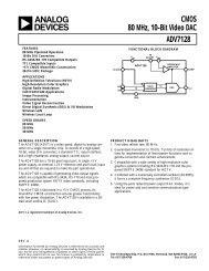
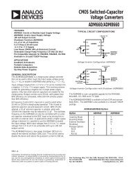
TABLE LOOKUP METHOD FOR COMPUTING DOW CRC Figure 4Current CRCValue (= CurrentTable Index)Input DataNew Index (= Current CRC xorInput Data)0000 0000 = 00 Hex 0000 0010 = 02 Hex (00 H xor 02 H) =02 Hex = 2 Dec1011 1100 = BC Hex 0001 1100 = 1C Hex (BC H xor 1C H) =A0 Hex = 160 Dec1010 1111 = AF Hex 1011 1000 = B8 Hex (AF H xor B8 H) =17 Hex = 23 Dec0001 1110 = 1E Hex 0000 0001 = 01 Hex (1E H xor 01 H) =1 F Hex = 31 Dec1101 1100 = DC Hex 0000 0000 = 00 Hex (DC H xor 00 H) =DC Hex = 220 Dec11110100 = F4 Hex 0000 0000 = 00 Hex (F4 H xor 00 H) =F4 Hex = 244 Dec0001 0101 = 15 Hex 0000 0000 = 00 Hex (15 H xor 00 H) =15 Hex = 21 Dec1010 0010 = A2 Hex 10100010 = A2 Hex (A2 H xor A2 H) =Hex = 0 DecCRC REGISTER COMBINED WITH 1’SCOMPLEMENT OF CRC REGISTER Figure 5CRC Register Value InputAPPLICATION NOTE 27Table (New Index)(= New CRC Value)Table[2]= 1011 1100 = BC Hex = 188 DecTable[160]= 1010 1111 = AF Hex = 175 DecTable[23]= 0001 1110 = 1E Hex = 30 DecTable[31]= 1101 110 = DC Hex = 220 DecTable[220]= 1111 0100 = F4 Hex = 244 DecTable [244]= 0001 0101 = 15 Hex = 21 DecTable[21]= 1010 0010 = A2 Hex = 162 DecTable[0]=0000 0000 = 00 Hex = 0 DecX 0 X 1 X 2 X 3 X 4 X 5 X 6 X 7 X 7 *1 X 0 X 1 X 2 X 3 * X 4 * X 5 X 6 X 6 *1 1 X 0 X 1 X 2 * X 3 X 4 * X 5 X 5 *1 1 1 X 0 X 1 * X 2 * X 3 X 4 * X 4 *0 1 1 1 X 0 X 1 * X 2 X 3 X 3 *1 0 1 1 0 X 0 * X 1 * X 2 X 2 *1 1 0 1 0 1 X 0 * X 1 * X 1 *0 1 1 0 1 0 1 X 0 * X 0 *0 0 1 1 0 1 0 1 Final CRC Value = 35 Hex, 53 DecimalNote: X i * = Complement of XiCRC-16 COMPUTATION FOR RAM RECORDS IN iButtonsAs mentioned in the introduction, some iButton devices have RAM in addition to the unique 8-byte ROMcode found in all iButtons. Because the amount of data stored in RAM can be large compared to the 8-byte ROM code, Dallas Semiconductor recommends using a 16-bit CRC value to ensure the integrity ofthe data, rather than the 8-bit DOW CRC used for the ROM. The particular CRC suggested is commonlyreferred to as CRC-16. The shift register <strong>and</strong> polynomial representations are given in Figure 6. The figureshows that for a 16-bit CRC, the shift register will contain 16 stages <strong>and</strong> the polynomial expression willhave a term of the sixteenth order. As stated previously, the iButton devices do not calculate the CRCvalues. The host must generate the value <strong>and</strong> then append the 16-bit CRC value to the end of the actualdata. Due to the uncertainty of the iButton’s “communication channel,” i.e., the two metal contactsurfaces, data transfers can experience errors that generally fall into three categories. First, briefintermittent connections can cause small numbers of bit errors to occur in the data, which the normalCRC-16 function is designed to detect. The second type of error occurs when contact is lost altogether,for example when the iButton is removed from the reader too quickly.8 of 16
APPLICATION NOTE 27This causes the last portion of the data to be read as logic 1s, since no connection to an iButton will beinterpreted as all 1s by the host. The normal CRC-16 function can also detect this condition under mostcircumstances. The third type of error is generated by a short circuit across the reader, which can becaused by an iButton that is not inserted correctly, or tilted significantly once in the reader. A short at thereader causes the data to be read as all 0s by the host. When using CRCs, this can cause problems, sincethe method to determine the validity of the data is to read the data plus the stored CRC value, <strong>and</strong> see ifthe resulting CRC computed at the host is 0000 Hex (for a 16-bit CRC.) If the reader was shorted, thedata plus the CRC value stored with the data will be read as all 0’s, <strong>and</strong> a false read will have occurred,but the CRC computed by the host will incorrectly indicate a valid read. In order to avoid this situation,Dallas Semiconductor recommends storing the complement of the computed CRC-16 value (CRC-16*)with the data that is written into the RAM. <strong>Using</strong> an uncomplemented CRC-16 value, the retrieval of datafrom the iButton is similar to the DOW CRC case. That is, if the CRC register in the host is initialized to0000 Hex <strong>and</strong> then all of the data plus the CRC-16 value stored with the data is read from the iButton, theresulting calculation by the host should have a 0000 Hex, as a final result. If instead, the complement ofthe CRC-16 value is stored with the data in the iButton, then the CRC register at the host is initialized to0000 Hex <strong>and</strong> the actual data plus the stored CRC-16* value is read. The resultant CRC value should beB001 Hex for a valid read. This greatly improves the operation of the system, since it can no longer befooled by a short at the reader. The reason that the CRC-16 function has these properties can be shown inan analogous manner to the DOW CRC case (see Figures 3 <strong>and</strong> 5). The operation of the 16-bit CRC isidentical in theory to the 8-bit version described earlier, but the properties of the CRC change since a 16-bit value is now available for error detection. For the CRC-16 function, the types of errors that aredetectable are:1. Any odd number of errors anywhere within the data record.2. All double-bit errors anywhere within the data record.3. Any cluster of errors that can be contained within a 16-bit “window” (1-16-bits incorrect).4. Most larger clusters of errors.CRC-16 HARDWARE DESCRIPTION AND POLYNOMIAL Figure 69 of 16
10 of 16APPLICATION NOTE 27The hardware implementation of the CRC-16 function is straightforward from the description given inFigure 6. Table 3 shows a software solution that is analogous to the hardware operations which computethe CRC-16 values using single-bit operations. As before, a less computation-intensive software solutioncan be developed through the use of a lookup table. The basic concepts presented for the 8-bit DOW CRClookup table also work for the CRC-16 case. A slight modification in procedure from the 8-bit case isrequired, however, because if the entire 16-bit result for the CRC-16 function were mapped into one tableas before, the table would have 2 16 or 65536 entries. A different approach is shown in Table 4, where the16-bit CRC values are computed <strong>and</strong> stored in two 256-entry tables, one containing the high order byte<strong>and</strong> the other the low order byte of the resultant CRC. For any current 16-bit CRC value, expressed asCurrent_CRC16_Hi for the current high order byte <strong>and</strong> Current _CRC16_Lo for the current low orderbyte, <strong>and</strong> any new input byte, the equation to determine the index into the high order byte table forlocating the new high order byte CRC value (New_CRC16_Hi) is given as:New_CRC16_Hi = CRC16_Tabhi[I] for I=0 to 255; where I = (Current_CRC16_Lo) EXOR (Input byte)The equation to determine the index into the low order byte table for locating the new low order byteCRC value (New_CRC16_Lo) is given as:New_CRC16_Lo = (CRC16_Tablo[I]) EXOR (Current_ CRC16_Hi) for I=0 to 255;where I = (Current_CRC16_Lo) EXOR (Input byte)An example of how this method works is shown in Figure 7.ASSEMBLY LANGUAGE FOR CRC-16 COMPUTATION Table 3crc_lo data 20h ; lo byte of crc calculation (bit addressable)crc_hi data 21h ; hi part of crc calculation;---------------------------------------------------------------------------; CRC16 subroutine.; - accumulator is assumed to have byte to be crc’ed; - two direct variables are used crc_hi <strong>and</strong> crc_lo; - crc_hi <strong>and</strong> crc_lo contain the CRC16 result;---------------------------------------------------------------------------crc16:; calculate crc with accumulatorpush b ; save value of bmov b, #08h ; number of bits to crc.crc_get_bit:crc_in_1:crc_cont:•••rrc a ; get low order bit into carrypush acc ; save a for later usejc crc_in_1 ;got a 1 input to crcmov c, crc_lo.0 ;xor with a 0 input bit is bitsjmp crc_cont ;continuemov c, crc_lo.0 ;xor with a 1 input bitcpl c ;is not bit.
crc_shiftjnc crc_shift ; if carry set, just shiftcpl crc_hi.6 ;complement bit 15 of crccpl crc_lo.1 ;complement bit 2 of crcmov a, crc_hi ; carry is in appropriate settingrrc a ; rotate itmov crc_hi, a ; <strong>and</strong> save itmov a, crc_lo ; again, carry is okayrrc a ; rotate itmov crc_lo, a ; <strong>and</strong> save itpop acc ; get acc backdjnz b, crc_get_bit ; go get the next bitpop b ; restore bretendAPPLICATION NOTE 27ASSEMBLY LANGUAGE FOR CRC–16 USING A LOOKUP TABLE Table 4crc_lo data 40h ; any direct address is okaycrc_hi data 41htmp data 42h;---------------------------------------------------------------------------; CRC16 subroutine.; - accumulator is assumed to have byte to be crc’ed; - three direct variables are used, tmp, crc_hi <strong>and</strong> crc_lo; - crc_hi <strong>and</strong> crc_lo contain the CRC16 result; - this CRC16 algorithm uses a table lookup;---------------------------------------------------------------------------crc16:xrl a, crc_lo ; create index into tablesmov tmp, a ; save indexpush dph ; save dptrpush dpl ;mov dptr, #crc16_tablo ; low part of table addressmovc a, @a+dptr ; get low bytexrl a, crc_hi ;mov crc_lo, a ; save of low resultmov dptr, #crc16_tabhi ; high part of table addressmov a, tmp ; indexmovc a, @a+dptr ;mov crc_hi, a ; save high resultpop dpl ; restore pointerpop dph ;ret; all done with calculation•••11 of 16
crc16_tablo:crc16_tabhi:dbdbdbdbdbdbdbdbdbdbdbdbdbdbdbdbdbdbdbdbdbdbdbdbdbdbdbdbdbdbdbdbdbdbdbdbdbdbdbdbdbdbdbdbdbdbdbdb000h, 0c1h, 081h, 040h, 001h, 0c0h, 080h, 041h001h, 0c0h, 080h, 041h, 000h, 0c1h, 081h, 040h001h, 0c0h, 080h, 041h, 000h, 0c1h, 081h, 040h000h, 0c1h, 081h, 040h, 001h, 0c0h, 080h, 041h001h, 0c0h, 080h, 041h, 000h, 0c1h, 081h, 040h000h, 0c1h, 081h, 040h, 001h, 0c0h, 080h, 041h000h, 0c1h, 081h, 040h, 001h, 0c0h, 080h, 041h001h, 0c0h, 080h, 041h, 000h, 0c1h, 081h, 040h001h, 0c0h, 080h, 041h, 000h, 0c1h, 081h, 040h000h, 0c1h, 081h, 040h, 001h, 0c0h, 080h, 041h000h, 0c1h, 081h, 040h, 001h, 0c0h, 080h, 041h001h, 0c0h, 080h, 041h, 000h, 0c1h, 081h, 040h000h, 0c1h, 081h, 040h, 001h, 0c0h, 080h, 041h001h, 0c0h, 080h, 041h, 000h, 0c1h, 081h, 040h001h, 0c0h, 080h, 041h, 000h, 0c1h, 081h, 040h000h, 0c1h, 081h, 040h, 001h, 0c0h, 080h, 041h001h, 0c0h, 080h, 041h, 000h, 0c1h, 081h, 040h000h, 0c1h, 081h, 040h, 001h, 0c0h, 080h, 041h000h, 0c1h, 081h, 040h, 001h, 0c0h, 080h, 041h001h, 0c0h, 080h, 041h, 000h, 0c1h, 081h, 040h000h, 0c1h, 081h, 040h, 001h, 0c0h, 080h, 041h001h, 0c0h, 080h, 041h, 000h, 0c1h, 081h, 040h001h, 0c0h, 080h, 041h, 000h, 0c1h, 081h, 040h000h, 0c1h, 081h, 040h, 001h, 0c0h, 080h, 041h000h, 0c1h, 081h, 040h, 001h, 0c0h, 080h, 041h001h, 0c0h, 080h, 041h, 000h, 0c1h, 081h, 040h001h, 0c0h, 080h, 041h, 000h, 0c1h, 081h, 040h000h, 0c1h, 081h, 040h, 001h, 0c0h, 080h, 041h001h, 0c0h, 080h, 041h, 000h, 0c1h, 081h, 040h000h, 0c1h, 081h, 040h, 001h, 0c0h, 080h, 041h000h, 0c1h, 081h, 040h, 001h, 0c0h, 080h, 041h001h, 0c0h, 080h, 041h, 000h, 0c1h, 081h, 040h000h, 0c0h, 0c1h, 001h, 0c3h, 003h, 002h, 0c2h0c6h, 006h, 007h, 0c7h, 005h, 0c5h, 0c4h, 004h0cch, 00ch, 00dh, 0cdh, 00fh, 0cfh, 0ceh, 00eh00ah, 0cah, 0cbh, 00bh, 0c9h, 009h, 008h, 0c8h0d8h, 018h, 019h, 0d9h, 01bh, 0dbh, 0dah, 01ah01eh, 0deh, 0dfh, 01fh, 0ddh, 01dh, 01ch, 0dch014h, 0d4h, 0d5h, 015h, 0d7h, 017h, 016h, 0d6h0d2h, 012h, 013h, 0d3h, 011h, 0d1h, 0d0h, 010h0f0h, 030h, 031h, 0f1h, 033h, 0f3h, 0f2h, 032h036h, 0f6h, 0f7h, 037h, 0f5h, 035h, 034h, 0f4h03ch, 0fch, 0fdh, 03dh, 0ffh, 03fh, 03eh, 0feh0fah, 03ah, 03bh, 0fbh, 039h, 0f9h, 0f8h, 038h028h, 0e8h, 0e9h, 029h, 0ebh, 02bh, 02ah, 0eah0eeh, 02eh, 02fh, 0efh, 02dh, 0edh, 0ech, 02ch0e4h, 024h, 025h, 0e5h, 027h, 0e7h, 0e6h, 026h022h, 0e2h, 0e3h, 023h, 0e1h, 021h, 020h, 0e0h12 of 16APPLICATION NOTE 27
dbdbdbdbdbdbdbdbdbdbdbdbdbdbdbdb0a0h, 060h, 061h, 0a1h, 063h, 0a3h, 0a2h, 062h066h, 0a6h, 0a7h, 067h, 0a5h, 065h, 064h, 0a4h06ch, 0ach, 0adh, 06dh, 0afh, 06fh, 06eh, 0aeh0aah, 06ah, 06bh, 0abh, 069h, 0a9h, 0a8h, 068h078h, 0b8h, 0b9h, 079h, 0bbh, 07bh, 07ah, 0bah0beh, 07eh, 07fh, 0bfh, 07dh, 0bdh, 0bch, 07ch0b4h, 074h, 075h, 0b5h, 077h, 0b7h, 0b6h, 076h072h, 0b2h, 0b3h, 073h, 0b1h, 071h, 070h, 0b0h050h, 090h, 091h, 051h, 093h, 053h, 052h, 092h096h, 056h, 057h, 097h, 055h, 095h, 094h, 054h09ch, 05ch, 05dh, 09dh, 05fh, 09fh, 09eh, 05eh05ah, 09ah, 09bh, 05bh, 099h, 059h, 058h, 098h088h, 048h, 049h, 089h, 04bh, 08bh, 08ah, 04ah04eh, 08eh, 08fh, 04fh, 08dh, 04dh, 04ch, 08ch044h, 084h, 085h, 045h, 087h, 047h, 046h, 086h082h, 042h, 043h, 083h, 041h, 081h, 080h, 040hAPPLICATION NOTE 27COMPARISON OF CALCULATION AND TABLELOOKUP METHOD FOR CRC-16 Figure 7Example:CRC register starting value: 90 F1 HexInput Byte: 75 HexCalculation MethodTable Lookup MethodCurrent CRC Value Input1001 0000 1111 0001 Current_CRC16_Lo = F1 Hex1 Current_CRC16_Hi = 90 Hex0100 1000 0111 1000 Input byte = 75 Hex00010 0100 0011 11001 Tabhi Index= (Current_CRC16_Lo) EXOR (Input byte)1011 0010 0001 1111 = F1 EXOR 75= 84 Hex = 132 Dec0 New_CRC16_Hi = Tabhi[132] = 63 Hex (from Table 4.)1111 1001 0000 111011101 1100 1000 011011100 1110 0100 00101 Tablo Index = (Current_CRC16_Lo) EXOR (Input byte) = 132 Dec1100 0111 0010 0000 Tablo[132] = 00 Hex (from Table 4.)0 New_CRC16_Lo = Tablo[132] EXOR (Current_CRC16_Hi)0110 0011 1001 0000 = 00 EXOR 90 = 90 HexNew CRC Value = 63 90 HexNew CRC Value = 63 90 Hex13 of 16
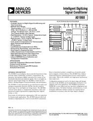
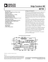
ASSEMBLY LANGUAGE PROCEDURE FORHIGH-SPEED CRC-16 COMPUTATION Table 5lo equ 40h ; low byte of CRChi equ 41h ; high byte of CRC•••APPLICATION NOTE 27crc16:crc0:crc1:crc2:push acc ; save the accumulator.xrl a, lomov lo, hi ; move the high byte of the CRC.mov hi, a ; save data xor low(crc) for latermov c, pjnc crc0xrl lo, #01h ; add the parity to CRC bit 0rrc a ; get the low bit in cjnc crc1xrl lo, #40h ; need to fix bit 6 of the resultmov c, acc.7xrl a, hi ; compute the results for other bits.rrc a ; shift them into placemov hi, a ; <strong>and</strong> save themjnc crc2xrl lo, #80h ; now clean up bit 7pop acc ; restore everything <strong>and</strong> returnret15 of 16
HIGH-SPEED CRC-16 COMPUTATION METHOD Figure 8APPLICATION NOTE 2716 of 16