Operating Guide HJSFDR SHUTTLE FEEDER - Hasler Inc.
Operating Guide HJSFDR SHUTTLE FEEDER - Hasler Inc.
Operating Guide HJSFDR SHUTTLE FEEDER - Hasler Inc.

Create successful ePaper yourself
Turn your PDF publications into a flip-book with our unique Google optimized e-Paper software.
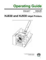
<strong>Operating</strong> <strong>Guide</strong>Mailing SystemsAnd SolutionsHASLERAmerica’s better choice®<strong>HJSFDR</strong><strong>SHUTTLE</strong> <strong>FEEDER</strong>An ISO 9001 Quality SystemCertified company
SAFETY PRECAUTIONSTHIS EQUIPMENT PRESENTS NO PROBLEM WHEN USED PROPERLY. HOWEVER, CERTAIN SAFETYRULES SHOULD BE OBSERVED WHEN OPERATING THE <strong>SHUTTLE</strong> <strong>FEEDER</strong>.BEFORE USING THE <strong>FEEDER</strong>, YOU SHOULD READ THIS MANUAL CAREFULLY AND FOLLOW THERECOMMENDED PROCEDURES, SAFETY WARNINGS, AND INSTRUCTIONS: Keep hands, hair, and clothing clear of rollers and other moving parts. Avoid touching moving parts or materials while the machine is in use. Before clearing a jam, be sure machinemechanisms come to a stop. Always turn off the machine before making adjustments, cleaning the machine, or performing any maintenancecovered in this manual. Use the power cord supplied with the machine and plug it into a properly grounded wall outlet located near themachine and easily accessible. Failure to properly ground the machine can result in sever personal injury and/orfire. The power cord and wall plug is the primary means of disconnecting the machine for the power supply. DO NOT use an adapter plug on the line cord or wall outlet. DO NOT remove the ground pin from the line cord. DO NOT route the power cord over sharp edges or trapped between furniture. Avoid using wall outlets that are controlled by wall switches, or shared with other equipment. Make sure there is no strain on the power cord caused by jamming between the equipment, walls or furniture. DO NOT remove covers. Covers enclose hazardous parts that should only be accessed by a qualified servicerepresentative. Report any damage of covers to your service representative. This machine requires periodic maintenance. Contact your authorized service representative for requiredservice schedules. To prevent overheating, do not cover the vent openings. Use this equipment only for its intended purpose.In addition, follow any specific occupational safety and health standards for your workplace or area.This manual is intended solely for the use and information of <strong>Hasler</strong>, <strong>Inc</strong>., its designated agents, customers, and theiremployees. The information in this guide was obtained from several different sources that are deemed reliable by allindustry standards. To the best of our knowledge, that information is accurate in all respects. However, neither<strong>Hasler</strong>, <strong>Inc</strong>. nor any of its agents or employees shall be responsible for any inaccuracies contained herein.All rights reserved. No part of this book may be reproduced or transmitted in any form or by any means, electronic or mechanical, includingphotocopying, recording, or any information storage and retrieval system, without permission in writing from the Publisher.
TABLE OF CONTENTSTABLE OF CONTENTSSection 1 – Getting Acquainted 1The <strong>HJSFDR</strong> Shuttle Feeder 1Main Control Panel 2Media Thickness and Separator Knob 2Sheet Length Switch 2Section 2 – Installation 3HJPAS System 3Installing on Other Printers 4Connecting the Shuttle Feeder to Other Systems 4Stand-alone Operation 4Section 3 – Setup and Operation 5Setting up the feeder 5Adjusting the Forwarding Roller 7Section 4 – Maintenance 9Cleaning 9Cleaning the Media Sensor 9Removing Jams in the Feeder 9Troubleshooting 10Appendix 11Specifications 11Index 13-i-
TABLE OF CONTENTSNotes-ii-
GETTING ACQUAINTEDSection 1 – Getting Acquainted1 RESETTABLE COUNTER – This counter keeps track of the number of pieces fed.2 <strong>FEEDER</strong> CONTROL PANEL – See description of controls on next page.3 OPERATOR SIDE-GUIDE – This guide helps to position the media.4 SHEET SEPARATOR ADJUSTMENT – This knob sets the depth of the sheetseparator. (See next page.)5 FEED ROLLER HEIGHT ADJUSTMENT – This knob adjusts the feed roller forproper feeding. (See next page.)6 NON-OPERATOR SIDE-GUIDE – This guide helps to position the media.7 <strong>SHUTTLE</strong> HEAD – The vacuum shuttle head feeds the media.8 REAR GUIDE – This guide keeps the media in the proper position for feeding.9 MEDIA LENGTH ADJUSTMENT – This knob is used when feeding media longerthan 13-inches. (See next page.)-1-
GETTING ACQUAINTEDMain Control Panel1 RESETTABLE COUNTER – Keeps track of the number of pieces run.2 STOP BUTTON – This button will stop the feeder and lockout the controls.3 MAIN POWER BUTTON – When the STOP switch is unlocked, this button will turnon the power to the feeder.4 JOG BUTTON – When the Main power is on and the Feeder Power switch is OFF, theJog button is used to feed material.5 POWER SWITCH – In the OFF position permits the operator to Jog the machine. Inthe ON position causes the machine to run continuously.6 VACUUM SWITCH – Turns the vacuum pump on.7 SPEED CONTROL – Controls the speed of the feeder.Media Thickness and Separator KnobsThe Separator Knob adjusts the height of the sheet separator. TheMedia Thickness Knob is used to adjust forwarding roller to themedia.Media Length SwitchThis switch is used to select the length of theMedia.-2-
INSTALLATIONSection 2 – InstallationHJPAS SystemAttaching the FeederMake sure that System is disconnected from the power source.Remove the covers from the feeder and main base cabinets.There are four (4) threaded holes on the Imaging System base.To assemble the Shuttle Feeder to the system align the four(4) holes in the feeder cabinet with the four threaded holes inthe base and attach with the Cap Head Screw and Washersupplied.Note: When attaching theShuttle Feeder it is necessaryto first mount a mountingbracket to the base of theShuttle Feeder so that therewill be four mounting holes toattach the feeder to the baseunit. This bracket is suppliedin the Shuttle Feeder kit and ismounted as shown with two screws that are supplied.Connecting the Shuttle Feeder to the Base1. The power cord from the feeder should be routedthrough the oval hole provided in the base unit and thepower cord should be plugged into the receptacle markedSwitchable.WARNINGTHE <strong>FEEDER</strong> POWER CORD SHOULD BEPLUGGED INTO THE RECEPTACLE BOXMARKED SWITCHABLE SO THAT WHEN THESTOP BUTTON ON THE BASE UNIT ISACTIVATED THE <strong>FEEDER</strong> WILL ALSO STOP.2. The jumper plug at the rear of the feeder should be removed and the cable fromprinter’s feeder connector installed in its place.-3-
INSTALLATIONInstalling on Other PrintersThe <strong>HJSFDR</strong> may be used with other printers such as the HJ3600 and HJ3800.Installing the Shuttle Feeder to a HJ3600 orHJ3800 requires that the Printer be placed on asuitable stand and the feeder rolled up to it.The four-wire cable supplied with the feeder isthen connected to the printer four-wire connectornext to the parallel port connection.The feeder will then start to feed when the selectbutton is pressed on the printer and stop feedingwhen the select button is again pressed.Stopping the printer from the Software ControlPanel will also stop the feeder.Connecting the Shuttle Feeder to Other SystemsThere are two ways to operate the feed functionof the <strong>HJSFDR</strong> when it is connected to machinesother than those marketed by <strong>Hasler</strong>, <strong>Inc</strong>.Connected to the four-pin connector at the rear ofthe feeder is a solid-state relay. This relay has anoperating range of 3 VDC to 32 VDC and offersa contact closure when activated, that causes theclutch on the feeder to operate and feed media.This function is accessed through pins 2 and 4 onthe four-pin connector. As long as the contactsare closed (the relay powered) the feeder will feed.An optional method of activating the feed from an external source is if the host machine has abuilt-in relay that has a spare contact. The contact if it activates when the host machine isrunning can be used to start the feeder. The Shuttle Feeder in this case can be accessed throughpins 1 and 3 on the four-pin connector. The external relay closing would cause the clutch toengage and feed media. As long as the contacts are closed, the feeder will feed.Stand-alone OperationThe Jumper Plug must be installed to run the feeder if it is not connected to the other machine.-4-
SETUP AND OPERATIONSection 3 – Setup and OperationSetting up the feederStep 1 – Choose and Install the Proper Vacuum PlateThe Shuttle Feeder kit contains four [4] Vacuum Plates. Each one works best with a specifictype of media. Refer to the chart below and select the plate for the media you will be feeding:MEDIAVACUUMPLATESingle sheets of paper. 1Thin post card stock 2Thick media up to 1/2-inches 3*Folded Media 4NOTE: *Use the P/N 28-105-45 Rear Pusher on media 1/4-inch or thicker to improvefeeding.1. Remove the Philips screw holding theVacuum Plate to the Vacuum arm.2. Remove the Plate3. Install the new plate and replace thescrew.Step 2 – Adjust the Forwarding Rollers to the Media1. Release the media thickness/separatorlocking lever [A].2. Raise the roller pressure lever [B] torelease the pressure between theforwarding rollers-5-
SETUP AND OPERATION3. Place one piece of the media under theforwarding rollers, then lower the rollerpressure lever [B].4. Adjust the Media Thickness knob [C] untilyou feel a slight drag on the media from therollers.Step 3 – Adjust the Sheet Separator1. Raise the sheet separator using theseparator adjustment knob [D]. Place asecond piece of media under the sheetseparator.2. Adjust the sheet separator knob [D] so thatthe second sheet of paper is held firmly bythe separator, but when it is removed, thesheet under it slides smoothly.3. Use the thickness/separator locking lever[A] to lock in the settings.Step 4 – <strong>Operating</strong> the Shuttle Feeder1. Center the media and adjust the two sideguides [1] to within 1/16-inch of themedia.2. Lock the side guide in place with thelocking levers [2].3. Adjust the rear guide [3] to within 1/16-inch of the rear of the media. Tighten thetwo locking knobs [4].4. Set the sheet length switch [11] to theproper position for the length of themedia. (UP TO 13 IN for media less than13-inches in length or OVER 13 IN for media over 13-inches in length.)5. Turn the STOP button [5] clockwise to release the switch. Then press the POWERbutton [6] to start the machine.6. Turn the VACUUM switch [9] to the ON position and set the SPEED to 1 or 2 [10].-6-
SETUP AND OPERATION7. Press and hold the JOG button [7] until one piece of media is fed. (This is to check yoursetup and feeding of the media.)8. Reset the COUNTER to Zero (0) by pressing the RED button next to the display.9. Turn the POWER switch [8] to ON to start continuous feeding.NOTE if the Shuttle Feeder is connected to a Print Stream II base unit the base unitshould be turned on and operating. When the SELECT button is pressed, thefeeder will start to feed if the power switch is ON. If the Shuttle Feeder is notconnected to a Print Stream II base unit then the jumper connector at the back ofthe machine must be connected or the machine will not feed.Adjusting the Forwarding RollerForwarding Roller Parallel AdjustmentThe lever [F] is used to adjust the parallel of theforwarding rollers in cases where the mediaskews. The lower forwarding rollers are springloaded and as a result, this adjustment does nothave to be preformed for every setup. It shouldonly be done when the rollers are replaced. Toperform the adjustment do the following:1. Release the thickness/separator lockinglever [A]. Then loosen the Hex Screw[E].2. Place 2 strips of 20 lb. paper under theforwarding rollers and adjust the MediaThickness knob [C] until one of the stripshas a slight drag in it.3. Lock lever [A] and adjust lever [F] untilthe drag on both sides is even, then tightenthe Hex Screw [E].-7-
SETUP AND OPERATIONNotes-8-
MAINTENANCESection 4 - MaintenanceCleaningWARNINGTHE <strong>HJSFDR</strong> PRINTER IS A PRECISION MACHINE THAT SHOULD BECLEANED REGULARLY TO INSURE MANY YEARS OF SERVICE.BEFORE PERFORMING ANY MAINTENANCE DISCONNECT THEMACHINE FROM ITS POWER SOURCE!The <strong>HJSFDR</strong> must be cleaned regularly of accumulated paper dust and ink. Depending on thetypes of media that are run, paper dust may accumulate within the printer and on the transport.Unplug the feeder from power receptacle and remove the covers.The internal areas are best cleaned with a vacuum that has a soft brush attachment to help loosenthe dust particles. Take care not to damage the PC Boards or electrical wiring.The exterior of the machine may be cleaned with any standard household cleaner which is nonabrasiveand does not contain plastic harming solvents.CAUTIONNEVER SPRAY OR POUR CLEANERS DIRECTLY ON OR INTO THE<strong>HJSFDR</strong> PRINTER. EXCESS LIQUID COULD HARM ELECTRONICPARTS. ALWAYS DAMPEN A RAG WITH THE CLEANER ANDAPPLY IT TO THE PARTS TO BE CLEANED.Cleaning the Media SensorPeriodically check the media sensor located just below the two large forwarding rollers. Thesensor should be clean and free of accumulated paper dust. Use a vacuum with a soft brushattachment or dry compressed air to remove the dust.Removing Jams in the FeederIf a jam occurs, STOP the Feeder.1. Turn off the feeder.2. Release the forwarding rollers by rotating the release lever clockwise.3. Remove any media in the hopper.4. Remove the jammed pieces from the hopper area.5. Rotate the forwarding roller release lever counterclockwise.6. Replace the media and restart the job.-9-
MAINTENANCETroubleshootingSome possible reasons for jamming are:1. Feeding more than one piece of media.2. Damaged media, such as dog-eared (turn down corners).3. Media that is not stiff enough may not be usable.4. Envelopes that are caught under the flap of another envelope or stuck to one another.-10-
APPENDIXAppendixSpecifications:MEDIA: Max Size: 14” Wide X 17” LengthMin Size:3” Wide X 5” LengthMax Thickness: 5/8”Min Thickness: 20 lb. Bond Paper (.004”)SPEED:PHYSICALDIMENSIONS:WEIGHT:ELECTRICAL:Up to 30,000 / HR26” L x 26” W x 42” H240 lbs.120 VAC 50/60 Hz 20 AMP (220 VAC optional)Specifications are subject to change without notice..-11-
APPENDIXNotes-12-
ASAdjusting for Media Length 6 Selecting Vacuum Plate 5Adjusting for Media Thickness 5 Sensor Cleaning 9Adjusting Forwarding Rollers 5, 7 Sheet Separator Adjustment 1, 2Adjusting Sheet Separator 6 Shuttle Head 1Attaching Feeder 3 Specifications 11C Speed Control 2Cleaning Machine 9 Stand Alone Operation 4Cleaning Sensor 9 Stop Button 2Connecting Feeder 3 TCounter 1 Trouble Shooting 10FVFeed Roll Height Adjustment 1 Vacuum Plate Selection 5Feeder Control Panel 1 Vacuum Switch 2Forwarding Roller Adjustment 5Forwarding Roller Parallel 7IInstalling on other Printers 4Installing on other System 4JJams 9Jog Button 2MMain Power Button 2Maintenance 9Media Length Adjustment 1Media Length Adjustment 2Media Thickness Adjustment 2NNon-Operator Side-<strong>Guide</strong> 1O<strong>Operating</strong> as a Stand Alone 4Operator Side-<strong>Guide</strong> 1PPower Switch 2RRear <strong>Guide</strong> 1Removing Jams 9Resettable Counter 1Resettable Counter 2INDEX-13-
INDEXNotes-14-
Part Number: 51104