TITAN MODEL 60 - Titan International
TITAN MODEL 60 - Titan International
TITAN MODEL 60 - Titan International

Create successful ePaper yourself
Turn your PDF publications into a flip-book with our unique Google optimized e-Paper software.
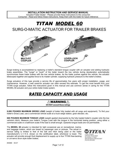
INSTALLATION INSTRUCTION AND SERVICE MANUALActuator/Trailer Dealer - Please provide these instructions to the consumer.Consumer - Read and follow these instructions. Keep them with the trailer for future reference.<strong>TITAN</strong> <strong>MODEL</strong> <strong>60</strong>SURG-O-MATIC ACTUATOR FOR TRAILER BRAKESSurge braking is accomplished by replacing a trailer's standard tongue coupler with an actuator and adding hydraulicbrake assemblies. The "surge" or "push" of the trailer toward the tow vehicle during deceleration automaticallysynchronizes these trailer brakes with the tow vehicle brakes. As the trailer pushes against the vehicle, the actuatortelescopes together and applies force to its master cylinder, supplying hydraulic pressure to the trailer's brakes.Surge actuators of this type provide a service life of approximately five years with proper installation, usage, andmaintenance. However, a well cared-for actuator can often exceed this estimate. To get the most benefit from your<strong>TITAN</strong> surge actuator, follow the instructions given in this manual and use common sense in caring for the <strong>TITAN</strong><strong>MODEL</strong> <strong>60</strong> actuator and your entire trailer brake system.RATED CAPACITY AND USAGE6,000 POUNDS MAXIMUM GROSS LOAD (weight of trailer fully loaded with all cargo and equipment). To find yourtrailer's Gross Load, use a commercial vehicle scale at a truck weigh station, grain elevator, etc.<strong>60</strong>0 POUNDS MAXIMUM TONGUE LOAD (weight applied downwards by the fully loaded trailer's coupler onto the towvehicle's hitch). Measure your trailer's Tongue Load with the tongue in the horizontal towing position, using either acommercial scale or a bathroom scale if the load is small enough. Upwards tongue loads are not permissible.The <strong>MODEL</strong> <strong>60</strong> actuator is intended for light occasional use on recreational, marine,and baggage trailers, which are towed by passenger cars or pickups. The actual inservicerating is limited to that of the ball and hitch being used or the trailermanufacturer's G.V.W.R. shown on the certification label, whichever is lower. Theactuator will provide enough fluid displacement to supply up to four <strong>TITAN</strong> free-backingor uni-servo drum style trailer brakes.#40989 05-07Page 1 of 12
INSTALLATION1. The <strong>MODEL</strong> <strong>60</strong> Actuator is completely assembled and ready to bolt into place onto straight three inch wide trailertongues. WELDING IS NOT RECOMMENDED since it will make repair or replacement difficult, destroy the platedor painted surface finish, and could potentially cause internal damage resulting in decreased brake performance. Ifthe actuator must be painted for aesthetic reasons, <strong>TITAN</strong> recommends painting ONLY the outer case, anddisassembling the unit prior to painting. Application of heavy coats of paint may interfere with component operation.Confirm the coupler and break-away mechanisms work properly before operation. Store actuators indoors and intheir original shipping carton until the time of installation.2. Bolt the actuator to the tongue using 1/2 inch by 4inch grade 5 bolts, nuts, and lock washers. The twoholes match standard coupler mounting holes onthree inch wide trailer tongues, as shown in Figure1. light weight tongues require spacer tubes insidefor reinforcement such as a 3/4 inch outsidediameter by eleven gauge piece of tubing. Using atorque wrench, tighten bolts to eighty (80) footpoundstorque.3. Install the hydraulic brakes and brake lines on thetrailer as described in the installation manualsupplied with the brakes. DO NOT crush or kink thetubing as you mount the actuator. <strong>TITAN</strong>recommends 3/16 inch brazed double wall tubingper S.A.E. J527 for use with all our actuator andbrake products. Use forty-five degree (45°) doubleflaretube ends per S.A.E. J533. DO NOT removeor modify the orifice connector at the rear ofyour actuator's master cylinder. It connects directlyto the brake tubing and ensures proper fluid flowcharacteristics.4. After installation of the actuator, brake, and brake lines as described above, proceed immediately to the "BRAKEFLUID FILLING AND BLEEDING" instructions.NOTE: Is the reference number shown in the assembly diagram of the actuator located at the end of this manual.Page 2 of 12
INSTALLATION (cont.)3. Fill the system with DOT-3 heavy duty hydraulic fluid using a pressure type brake bleeder. (This type of brakebleeder is available at your local automotive jobber.) Follow manufacturer's directions.Brake Fluid Filling and Bleeding3a. After completing the “Installation” instructions, remove the master cylinder cap and fill the reservoir to threequartersfull with DOT-3 brake fluid. DO NOT allow brake fluid to contact painted surfaces since it willdamage the finish. Wipe up any spills immediately and wash the area with water.3b. If you choose to manually bleed the system, an assistant makes the job easier. Please note the diagram infigure 2 (on the next page). Disconnect the trailer from the tow vehicle and hook the safety chains (NOTthe actuator breakaway cable) together to form a loop. The loop should be centered below the actuator’scoupler as shown in Figure 2.3c. Place a sturdy board such as a 2 x 4 into the safety chain loop below the coupler. The board should be fourfeet long or more so it will extend well above the actuator. Position the board to press against the front endof the actuator’s coupler and use it to force the coupler case into the actuator’s outer housing. This pumpsthe brake fluid into the trailer braking system. Manually pull the coupler case back to fully extended positionand repeat the process.3d. When the air bubbling stops inside the master cylinder, install a bleeder hose on the bleeder screw of thefirst wheel cylinder to be bled. Start with the rear axle on tandem axle trailers. Submerge the other end ofthe hose in a glass container of brake fluid so that air bubbles can be observed. Open the bleeder screwone turn before pushing the coupler case in. When the coupler is pushed completely in, the bleeder screwshould be closed to prevent air from being pulled back into the system. Air trapped in the brake lines willgreatly reduce your braking efficiency. Repeat this process until no more bubbles are released with eachstroke. Be sure to close the bleeder screw securely.3e. Repeat the bleeding operation at each wheel cylinder. During the bleeding process, replenish the brakefluid so the level does not fall below half full level in the master cylinder reservoir. When bleeding iscomplete, fill the reservoir to within 3/8” of the top. Install the filler cap securely.NOTE: Is the reference number shown in the assembly diagram of the actuator located at the end of this manual.Page 3 of 12
TESTING <strong>TITAN</strong> SURGE BRAKE SYSTEMSHydraulic surge actuator systems provide automatic and smooth trailer braking without special application by the towvehicle driver. While this is extremely convenient it can sometimes be difficult to determine if the surge setup isfunctioning properly. The following steps provide a quick field-test to confirm that the trailer brake system is operational.1. Move the trailer to flat, level ground, pulling FORWARD several feet before parking. This forward motion willensure trailers equipped with free-backing brakes are in their normal operating mode. Disconnect the 'trailer fromthe tow vehicle and jack the trailer's tongue until it is horizontal.2. Hook the trailer's safety chains (NOT the actuator's breakawaycable/chain) together to form a loop, which is centered belowthe actuator's coupler as shown in Figure 2.3. Place a sturdy board, such as a 2 inch by 4 inch piece oflumber, into the chain loop below the coupler. The boardshould be 4 feet or longer so it will extend several feet abovethe actuator. Keep the end of the board a few inches off theground, and position it to press against the front end of theactuator's coupler.4. Stand in front of the trailer and face the rear. Apply force tothe top end of the board to use it as a lever. Press backtowards the rear of the trailer. The board will begin moving thecoupler case (inner slide) into the actuator’s outer housing.5. Keep pressing the top of the board to stroke the actuator and its internal master cylinder. If the trailer brakesystem is operational, the brakes will apply and keep the trailer from rolling away from you. Properly adjusted uniservoor duo-servo type brakes will prevent you from moving the trailer back more than a few inches. Freebackingtype brakes will initially provide rolling resistance, but continued force on the board will switch them intofree-backing mode, and you’ll be able to move the trailer backwards.6. If you have uni-servo or duo-servo brakes, and stroking the actuator (as described previously) causes the trailerto roll away from you freely or with only minimal resistance, the brakes are NOT applying properly. If you havefree-backing brakes, and stroking the actuator (as described previously) causes the trailer to roll away withoutinitial resistance, the brakes are NOT applying properly. The brake system MUST be evaluated to determine thecause of the problem, and corrective action MUST be taken before the trailer is used.Use this procedure each time you tow your trailer to check your surge brake system operation.NOTE: Is the reference number shown in the assembly diagram of the actuator located at the end of this manual.Page 4 of 12
HITCHING TRAILER1. Confirm the towing hitch and ball have a rating equal to or greater than the trailer G.V.W.R. and are properly andsecurely attached to the tow vehicle. The hitch MUST be installed so the trailer tongue is level (horizontal) whencoupled to the tow vehicle.2. To attach the actuator to the tow vehicle, follow the procedure below which corresponds to your actuator’s couplertype.2A. MULTI-FIT COUPLER:The multi-fit (hand wheel) coupler will accept 1-7/8 inch, 50 millimeter, and 2 inch diameter tow balls. Open thecoupler by depressing the hand wheel lock and turning the hand wheel fully counterclockwise until itsrotation is stopped by the lock ring . Lower the coupler onto the ball, confirming that the ball is fully seated inthe coupler socket. Tighten the hand wheel in a clockwise direction to secure the ball. The hand wheel lock shouldclick as you turn the hand wheel, to confirm that the hand wheel will stay tightened. Turn the hand wheel until it canno longer be turned by hand, and then back it off until the lock catches in the nearest notch on the bottom of thehand wheel. Check that the ball latch has been drawn up snugly under the tow ball, trapping it in the couplersocket. Do not tow the trailer if the coupler is damaged.2B. LEVER-LOCK COUPLER:The lever-lock coupler is preset at the <strong>TITAN</strong> factory to fit 2" trailer balls. It can be adjusted to fit 1-7/8 inch or 50millimeter diameter tow balls by tightening the coupler's locknut , which is underneath the ball latch . Afteradjustment, make sure that the sides of the locknut is trapped between the flanges of the lock plate so that thelocknut can not vibrate loose during trailering. Open the coupler by pressing the handle assembly's locktrigger so it unhooks from the lock plate's loop, and then by swinging the handle forward. Lower the coupler onto theball, confirming that the ball is fully seated in the coupler socket. Swing the handle upwards until the lock triggerhooks onto the lock plate loop to secure the ball. Check that the ball latch has been drawn up snugly underthe tow ball, trapping it in the coupler socket, and that the lock trigger is firmly hooked onto the lock plate loop. Aproperly adjusted lever-lock coupler will have between 1/64 inch and 1/32 inch of free play between the ball and ballsocket. Do not tow the trailer if the coupler is damaged.3. Check that the actuator’s coupler is securely latched onto the tow ball by extending the trailer’s tongue jack to theground. Use it to lift the trailer tongue and tow vehicle hitch two to four inches. The coupler and ball should remainengaged. DO NOT tow the trailer unless the coupler is latched onto the ball securely. Retract the trailertongue jack before towing.4. Confirm the towing hitch and ball have a rating equal to or greater than the trailer G.V.W.R. and are properly andsecurely4A. MULTI-FIT COUPLER:Confirm that the tow ball is fully secured in the coupler as previously described. Insert a standard padlock throughthe holes in the side of the hand wheel . The padlock will stop against the bracket on top of the couple case and further prevent the hand wheel from rotating and opening. Do not use padlocks which interfere with thetelescoping action of the actuator and thereby compromise braking performance.4B. LEVER-LOCK COUPLER:Confirm that the tow ball is fully secured in the coupler as previously described. With the handle in the locked CMI!)position, insert either a standard padlock or spring pin through the hole in the side of the handle assembly .This will lock the handle to the handle bolt and further prevent the handle assembly from swinging forward andopening. Do not use padlocks or pins which interfere with the telescoping action of the actuator and therebycompromise braking performance.NOTE: Is the reference number shown in the assembly diagram of the actuator located at the end of this manual.Page 5 of 12
HITCHING TRAILER (cont.)5. As shown in Figure 3, your tow vehicle's hitch provides a safety chain hole or ring on each side. Attach your trailer'ssafety chains securely to these connection points, being sure to cross the chains UNDER the trailer tongue. Safetychains MUST be used. This will prevent the trailer tongue from dropping to the road if the coupler separates from thetow vehicle's hitch. If your tow vehicle's hitch does not provide safety chain connection points, have appropriate onesadded by a reputable hitch installer.6. Attach the actuator's break-away cable S-hook securely to one of the tow vehicle hitch's safety chainconnection points. Confirm that the trailer's safety chains are adjusted relative to the actuator's break-away cable asnoted previously. DO NOT loop the break-away cable around a bracket and hook it back onto itself.7. Before towing, check that the break-away lever assembly is properly positioned as shown on the coverillustration of this manual.8. Before If the break-away lever and cable are not located correctly, due to either the cable being pulled during use orby accident, it MUST be reset prior to the trailer being moved.Resetting the Break-away Lever is accomplished by first removing the two screws which retain the cover overthe break-away spring . This will allow the cover to be lifted. By pulling the break-away lever slightly furtherforward, you'll be able to pry the break-away spring carefully out of the notch in the outer case to release the breakawaylever. When removing the break-away spring, be careful not to deform it.NOTE: Is the reference number shown in the assembly diagram of the actuator located at the end of this manual.Page 6 of 12
HITCHING TRAILER (cont.)8. (cont) Inspect all break-away system components for damage.Replace any damaged items with genuine <strong>TITAN</strong> service parts.With the break-away spring removed, the lever can now bereturned to its original position. Check that the tip of the breakawaylever which is inside the outer case , is in FRONT ofthe push rod assembly . Also confirm that the roll-pin, whichis pressed through the break-away lever, has remained inside theouter case. Following Figure 4, reinsert the break-away springinto the outer case notch, with the spring flange in the lever'supper detent groove. Replace the cover and fasten it securelywith the two screwsIf the hydraulic pressure being held in the system is too great topermit the break-away spring to be easily pried out, it can also bereleased by removing the front roller bolt . This will allow thefront of the coupler case to swing down and free the breakawaylever. The break-away spring can then be pried out andreset as described above. Be sure to reassemble the rollers with their chamfered ends out against the walls of the couplercase . Tighten the locknuts on the roller bolts just tozero free-play between the outer case and the coupler case, and then back the locknuts off one-half turn. Over tighteningwill restrict proper surge operation.10. Sway control devices that restrict operation of the actuator CANNOT be used. The actuator MUST be free totelescope in response to braking requirements.11. The actuator is designed for use with Free-Backing or Uni-Servo drum style trailer brakes. Do not block the surgeaction in order to back up with other brake types due to potential system damage. Failure to remove block willalso prevent forward braking.12. To uncouple the trailer, first block the wheels to keep the trailer from rolling. Unhook the actuator's breakawaycable and the trailer's safety chains from the tow vehicle. Then open your coupler as described previously in thesection which corresponds to your actuator's coupler type. Finally, lift the trailer tongue off the tow ball, using atongue jack if necessary.NOTE: Is the reference number shown in the assembly diagram of the actuator located at the end of this manual.Page 7 of 12
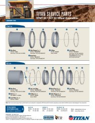
MAINTENANCE1. Before each towing, perform the following steps:- Check that the brake fluid reservoir is three-quarters full of DOT-3 or DOT-4 brake fluid. Check for leaks andrepair as required.- Examine the actuator for wear, bent parts, corroded/seized parts, or other damage. Have the affectedcomponents replaced with genuine <strong>TITAN</strong> service parts. Check to determine that the actuator mounting bolts(where applicable) are tightened to eighty (80) foot-pounds torque using a torque wrench.- Test the actuator and brake function as described in the “TESTING <strong>TITAN</strong> SURGE BRAKE SYSTEMS”section of this manual. Actuator travel over one inch indicates that the brakes need adjustment (or that theactuator has been structurally damaged). Actuator travel is the distance the coupler case assembly moves relative to the outer case during braking. Adjust the brakes following the instructions given in thebrake installation manual. In general, back off adjusters ten clicks from locked drum rotation. Adjust freebackingbrakes by rotating in the forward direction only. Failure to adjust brakes will result in loss of braking.2. The only adjustments on the actuator itself are the self-locking nuts on the two roller bolts . Tighten theLocknuts just to zero free-play between the outer case and the coupler case , and then back the locknutsoff one-half turn. Over-tightening will restrict proper surge operation.3. A film of clean grease on the ball will minimize squeaking. Wipe the ball clean and renew film each time the traileris used.4. Before towing, examine the actuator for bent parts or wear. Replace parts as necessary. Check to determine thatmounting bolts are tight and welds not cracked.5. Actuator travel (over one inch) shown by front roller path indicates a need to adjust the brakes. Adjust perinstructions found in brake installation manual. In general, back-off adjusters 10 clicks from locked rotation. AdjustFree-Backing brakes by rotating in forward direction only. Failure to adjust may result in loss of braking.6. Before storage or after extended use, <strong>TITAN</strong> recommends applying motor oil to the coupler components andinternal rollers to keep them moving freely and to prevent corrosion.<strong>MODEL</strong> <strong>60</strong> PRODUCT LISTDRUM BRAKEDISC BRAKEDESCRIPTION w/90 degree elbow w/90 degree elbowLever lock,plated4332900 4332901 4715400 4715401Lever lock,painted4338<strong>60</strong>0 4338<strong>60</strong>1 4819900 4819901Multi-fit plated 4339700 4339701 4745700 4745701Multi-fit painted 4339900 4339901 4815200 4815201Master cylinder 2336100042 4714200042NOTE: Is the reference number shown in the assembly diagram of the actuator located at the end of this manual.Page 8 of 12
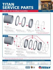
RefNo.Part No.<strong>MODEL</strong> <strong>60</strong> ACTUATOR PARTS LISTDescriptionMulti-FitMarine43397,47457Multi-FitPainted43399,48152Lever-LockMarine43329,471541 4324<strong>60</strong>0 Outer Case 1 11 4338700 Outer Case 1 12 2337700 Strut 1 1 1 13 2337800 Coupler Case 13 4097000 Coupler Case 13 4332500 Coupler Case 13 4338800 Coupler Case 14 2336200 Shock Absorber 1 1 1 15 2339000 Bolt, Hex 7/16 NF x 2-5/8 1 1 1 16 2339100 Locknut, Hex 7/16 NF Thin 1 1 1 17 2327800 Roller 4 4 4 48 2341300 Bolt, Hex 1/2 NF x 3-3/4 2 2 2 29 1861200 Locknut, Hex 1/2 NF 2 2 3 310 4623800 Breakaway Assy. w/pin, cover, s-hook 1 1 1 111 1055500 S-hook - included with 46238 1 1 1 113 4005200 Breakaway Spring 1 1 1 114 2346300 Push Rod Assembly 1 1 1 115 * 2336100042 Master Cylinder - Drum Brake 1 1 1 115 * 4714200042 Master Cylinder - Disc Brake 1 1 1 116 * 2341400 Gasket 1 1 1 117 * 1209800 Connector, 1/64" orifice - Drum Brake 1 1 1 117 * 4750300 Connector - Disc Brake 1 1 1 118 * 1050800 Bolt, Hex 1/4 NC x 3/4 4 4 4 419 * 07994000 Lock washer 1/4 4 4 4 420 * 4480701 Filler ap, 1-1.4-18 NEF plastic 1 1 1 121 * 2338900 Gasket, Filler Cap 1 1 1 122 * 2356<strong>60</strong>0 Cover, Master Cylinder 1 1 1 123 2338100 Latch Bolt 1 124 1809000 Lock Plate 1 1 1 125 4335800 Ball Latch 1 1 1 126 4336800 Spring 1 1 1 127 2338300 Hand Wheel Lock 1 128 2420000 Hand Wheel 1 129 2496400 Lock Ring 1 130 2452500183 Cover, Front 2 230 2452500317 Cover, Front 2 231 1094100 Screw, Cover 6 6 6 632 4358500 Handle Assembly 1 133 4334500 Spring Plate 1 134 4045400 Multi-Fit Coupler Repair Kit 1 135 4358400 Lever-Lock Coupler Repair Kit 1 136 1502<strong>60</strong>0 Master Cylinder Repair Kit Wagner 1 1 1 137 4395100 Master Cylinder Kit (includes * parts) Drum Brakes 1 1 1 137 4820000 Master Cylinder Kit (includes * parts) Disc Brakes 1 1 1 1Lever-LockPainted43386,48199NOTE: Is the reference number shown in the assembly diagram of the actuator located at the end of this manual.Page 9 of 12
<strong>MODEL</strong> <strong>60</strong> PARTS DIAGRAMPage 10 of 12
<strong>MODEL</strong> <strong>60</strong> PARTS DIAGRAM (cont.)Page 11 of 12
LIMITED WARRANTYLimited Warranty <strong>Titan</strong> Tire Corporation (<strong>TITAN</strong>) warrants its products to be free from defects in material and workmanship for one year from dateof delivery to the original purchaser when properly installed, used and maintained by the purchaser.This warranty does not apply to damage or loss caused by any or all of the following circumstances or conditions: Freight damage. Parts, accessories, materials or components not obtained former approved in writing by <strong>TITAN</strong>. Misapplication, misuse and failure to follow the directions or observe cautions and warnings on installation, operation, application,inspection or maintenance specified in any <strong>TITAN</strong> quotations, acknowledgements, sales literature, specification sheet or installationinstructions and service manual (“applicable literature”)If any <strong>TITAN</strong> products are found upon <strong>TITAN</strong>’s examination to have been defective when supplied, <strong>TITAN</strong> will either: credit the purchaser’s accountfor the purchase price of the <strong>TITAN</strong> product; or repair the product. <strong>TITAN</strong> has sole discretion in choosing which option to provide. For this LIMITEDWARRANTY to apply, <strong>TITAN</strong> must receive notice of the alleged defect within 30 days of either the discovery of the alleged defect or the expiration ofthe warranty period, whichever is earlier. Any claim not made with in this period shall conclusively be deemed waived.If requested by <strong>TITAN</strong>, purchaser shall return the alleged defective product to <strong>TITAN</strong> for examination at <strong>Titan</strong>’s direction and expense. <strong>TITAN</strong> will notpay for expenses incurred in returning a product to <strong>TITAN</strong> without <strong>TITAN</strong>’S prior written authority. <strong>TITAN</strong> shall not be liable for any other expensespurchaser incurs to remedy any defect. Purchasers waive subrogation on all claims under any insurance.Limitation of Liability It is expressly agreed that the liability of <strong>TITAN</strong> is limited and <strong>TITAN</strong> does not function as an insurer. THE REMEDIES SETFORTH IN THIS WARRANTY SHALL CONSTITUTE THE EXCLUSIVE REMEDIES AVAILABLE TO THE PURCHASER OR USER AND ARE INLIEU OF ALL OTHER REMEIDIES, EXPRESS OR IMPLIED. THE LIABILITY OF <strong>TITAN</strong>, WHETHER IN CONTRACT, IN TORT, UNDER ANYWARRANTY OR OTHERWISE, SHALL NOT EXCEED THE PURCHASE PRICE OF THE PARTICULAR PRODUCT MANUFACTURED, SOLD ORSUPPLIED BY <strong>TITAN</strong>.To Obtain Technical Assistance To enable <strong>TITAN</strong> to respond to a request for assistance or evaluation of customer or user operation difficulty,please provide at a minimum the following information by calling 1-800-872-2327 or within Iowa 1-515-265-9200: Model number, serial number and all other data on the specific component which appears to be involved in the difficulty. The date and from whom you purchased your <strong>TITAN</strong> product. State your difficulty, being sure to mention at least the following: Application, Nature of load involved, and Weight of the load.Field Service If field service at the request of the purchaser is rendered and the difficulty is found not to be with <strong>TITAN</strong>’S product, the purchasershall pay the time and expense (at the prevailing rate at the time of service) of the seller’s field representative(s). Charges for service, labor and otherexpenses that have been incurred by the purchaser, its customer or agent without prior written authorization of <strong>TITAN</strong> will not be accepted.<strong>TITAN</strong> EXTENDS NO WARRANTY, EXPRESS OR IMPLIED, ON PRODUCTS NOT MANUFACTURED BY <strong>TITAN</strong> OR TO <strong>TITAN</strong>’S DESIGNSPECIFICATION, INCLUDING BUT NOT LIMITED TO SUCH ITEMS AS NON-<strong>TITAN</strong> TIRES, BRAKES, ACTUATORS, BEARINGS, HOSE ANDTUBING, PURCHASER’S RECOURSE SHALL BE LIMITED TO ANY WARRANTY OF THE PERSPECTIVE MANUFACTURERS.THIS WARRANTY EXCLUDES ALL IMPLIED WARRANTIES OF MERCHANTABILITY OR FITNESS FOR A PARTICULAR PURPOSE OR ANYPURPOSE.THIS WARRANTY DOES NOT COVER NOR EXTEND TO INCIDENTAL OR CONSEQUENTIAL DAMAGE. Some states do not allow the exclusionor limitation of incidental or consequential damages, so the above limitation or exclusion may not apply to you.No representative has authority to make any representation, promise or agreement except as stated in this Limited Warranty. <strong>TITAN</strong> reserves theright to make design and other changes upon its products without any obligation to install the same on any previously sold or delivered products.THERE ARE NO WARRANTIES WHICH EXTEND BEYOND THOSE DESCRIBED ABOVE. EFFECTIVE JANUARY 1, 1998 THISWARRANTY SUPERSEDES ALL PRIOR WARRRANTIES, WRITTEN OR IMPLIED.Page 12 of 12