cavalok cavity closer and frame
cavalok cavity closer and frame
cavalok cavity closer and frame

You also want an ePaper? Increase the reach of your titles
YUMPU automatically turns print PDFs into web optimized ePapers that Google loves.
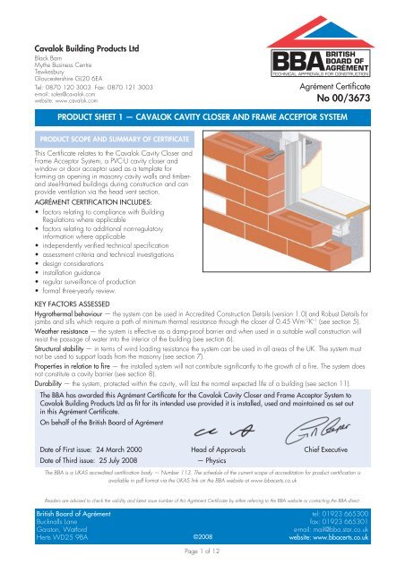
Cavalok Building Products LtdBlack BarnMythe Business CentreTewkesburyGloucestershire GL20 6EATel: 0870 120 3003 Fax: 0870 121 3003e-mail: sales@<strong>cavalok</strong>.comwebsite: www.<strong>cavalok</strong>.comAgrément CertificateNo 00/3673PRODUCT SHEET 1 — CAVALOK CAVITY CLOSER AND FRAME ACCEPTOR SYSTEMPRODUCT SCOPE AND SUMMARY OF CERTIFICATEThis Certificate relates to the Cavalok Cavity Closer <strong>and</strong>Frame Acceptor System, a PVC-U <strong>cavity</strong> <strong>closer</strong> <strong>and</strong>window or door acceptor used as a template forforming an opening in masonry <strong>cavity</strong> walls <strong>and</strong> timber<strong>and</strong>steel-<strong>frame</strong>d buildings during construction <strong>and</strong> canprovide ventilation via the head vent section.AGRÉMENT CERTIFICATION INCLUDES:• factors relating to compliance with BuildingRegulations where applicable• factors relating to additional non-regulatoryinformation where applicable• independently verified technical specification• assessment criteria <strong>and</strong> technical investigations• design considerations• installation guidance• regular surveillance of production• formal three-yearly review.KEY FACTORS ASSESSEDHygrothermal behaviour — the system can be used in Accredited Construction Details (version 1.0) <strong>and</strong> Robust Details forjambs <strong>and</strong> sills which require a path of minimum thermal resistance through the <strong>closer</strong> of 0.45 Wm –2 K –1 (see section 5).Weather resistance — the system is effective as a damp-proof barrier <strong>and</strong> when used in a suitable wall construction willresist the passage of water into the interior of the building (see section 6).Structural stability — in terms of wind loading resistance the system can be used in all areas of the UK. The system mustnot be used to support loads from the masonry (see section 7).Properties in relation to fire — the installed system will not contribute significantly to the growth of a fire. The system doesnot constitute a <strong>cavity</strong> barrier (see section 8).Durability — the system, protected within the <strong>cavity</strong>, will last the normal expected life of a building (see section 11).The BBA has awarded this Agrément Certificate for the Cavalok Cavity Closer <strong>and</strong> Frame Acceptor System toCavalok Building Products Ltd as fit for its intended use provided it is installed, used <strong>and</strong> maintained as set outin this Agrément Certificate.On behalf of the British Board of AgrémentDate of First issue: 24 March 2000 Head of Approvals Chief ExecutiveDate of Third issue: 25 July 2008— PhysicsThe BBA is a UKAS accredited certification body — Number 113. The schedule of the current scope of accreditation for product certification isavailable in pdf format via the UKAS link on the BBA website at www.bbacerts.co.ukReaders are advised to check the validity <strong>and</strong> latest issue number of this Agrément Certificate by either referring to the BBA website or contacting the BBA direct.British Board of Agrément tel: 01923 665300Bucknalls Lane fax: 01923 665301Garston, Watforde-mail: mail@bba.star.co.ukHerts WD25 9BA©2008website: www.bbacerts.co.ukPage 1 of 12
RegulationsIn the opinion of the BBA, the Cavalok Cavity Closer <strong>and</strong> Frame Accepter System, if used in accordance with theprovisions of this Certificate, will meet or contribute to meeting the relevant requirements of the following BuildingRegulations:The Building Regulations 2000 (as amended) (Engl<strong>and</strong> <strong>and</strong> Wales)Requirement: C2(b) Resistance to moistureComment:The system prevents the passage of moisture from the outer leaf to the inner leaf of a <strong>cavity</strong> wall atwindow or door openings. See sections 6.1 to 6.4 of this Certificate.Requirement: C2(c) Resistance to moistureComment:The system can contribute to meeting this Requirement. See sections 5.3 <strong>and</strong> 5.4 of this Certificate.Requirement: F1 Means of ventilationComment:Background ventilation can be provided to meet this Requirement. See sections 3.5 <strong>and</strong> 3.6 of thisCertificate.Requirement: L1(a)(i) Conservation of fuel <strong>and</strong> powerComment:The system contributes to minimising heat loss at jambs <strong>and</strong> sills. See sections 5.1 <strong>and</strong> 5.2 of thisCertificate.Requirement: Regulation 7 Materials <strong>and</strong> workmanshipComment:The system is acceptable. See section 11 <strong>and</strong> the Installation part of this Certificate.In addition to the contribution which the system can make to meeting the relevant Requirements, the following comments shouldbe noted:Requirement: A1 LoadingComment:When used in conventional masonry <strong>cavity</strong> walls, the system will not adversely affect the structuralstability of the walls. Use of the system does not obviate the need for conventional wall ties between theinner <strong>and</strong> outer leaves at window <strong>and</strong> door openings. See sections 7.1 <strong>and</strong> 7.2 of this Certificate.Requirement: B3(4) Internal fire spread (structure)Comment:The system can be used in constructions that meet this Requirement. See sections 8.1 to 8.3 of thisCertificate.The Building (Scotl<strong>and</strong>) Regulations 2004 (as amended)Regulation: 8(1)(2) Fitness <strong>and</strong> durability of materials <strong>and</strong> workmanshipComment:The system can contribute to a construction satisfying this Regulation. See sections 10 <strong>and</strong> 11 <strong>and</strong> theInstallation part of this Certificate.Regulation: 9 Building st<strong>and</strong>ards — constructionSt<strong>and</strong>ard: 3.10 PrecipitationComment:Walls incorporating the system can satisfy this St<strong>and</strong>ard, with reference to clauses 3.10.1 (1)(2) <strong>and</strong>3.10.3 (1)(2) . See sections 6.1 to 6.4 of this Certificate.St<strong>and</strong>ard: 3.14 VentilationComment: Background ventilation can be provided to satisfy this St<strong>and</strong>ard, with reference to clauses 3.14.2 (2) ,3.14.3 (1)(2) <strong>and</strong> 3.14.5 (1) . See sections 3.5 <strong>and</strong> 3.6 of this Certificate.St<strong>and</strong>ard: 3.15 CondensationComment: The system can contribute to minimising the risk of condensation, with reference to clauses 3.15.1 (1) ,3.15.4 (1) <strong>and</strong> 3.15.5 (1) . See sections 5.3 <strong>and</strong> 5.4 of this Certificate.St<strong>and</strong>ard: 6.1(b) Carbon dioxide emissionsSt<strong>and</strong>ard: 6.2 Building insulation envelopeComment: The system can contribute to minimising heat loss at jambs <strong>and</strong> sill, with reference to clauses 6.2.3 (1) ,6.2.4 (1)(2) <strong>and</strong> 6.2.5 (2) . See section 5.1 of this Certificate.Regulation: 12 Building st<strong>and</strong>ards — conversionsComment:All comments given for this system under Regulation 9, also apply to this Regulation, with reference toclause 0.12.1 (1)(2) <strong>and</strong> Schedule 6 (1)(2) .In addition to the contribution which the system can make to satisfying the relevant St<strong>and</strong>ards, the following comments shouldbe noted:Regulation: 9 Building st<strong>and</strong>ards — constructionSt<strong>and</strong>ard: 1.1(a)(b) StructureComment:When used in conventional masonry <strong>cavity</strong> walls the system will not obviate the need for conventionalwall ties between the inner <strong>and</strong> outer leaves at window <strong>and</strong> door openings, with reference to clause1.1.1 (1)(2) . Door <strong>frame</strong>s require additional fixings. See sections 7.1 <strong>and</strong> 7.2 of this Certificate.St<strong>and</strong>ard: 2.4 CavitiesComment:In conjunction with a <strong>cavity</strong> barrier, the system can satisfy this St<strong>and</strong>ard, with reference to clause2.4.1 (1)(2) <strong>and</strong> Annex 2.B (1) or 2.D (2) . The system does not constitute a <strong>cavity</strong> barrier. See sections 8.1 to8.3 of this Certificate.(1) Technical H<strong>and</strong>book (Domestic).(2) Technical H<strong>and</strong>book (Non-Domestic).Page 2 of 12
The Building Regulations (Northern Irel<strong>and</strong>) 2000 (as amended)Regulation: B2 Fitness of materials <strong>and</strong> workmanshipComment:The system is acceptable. See section 11 <strong>and</strong> the Installation part of this Certificate.Regulation: B3(2) Suitability of certain materialsComment:The system is acceptable. See section 10 of this Certificate.Regulation: C4(b) Resistance to ground moisture <strong>and</strong> weatherComment:Walls incorporating the system can contribute to meeting this Regulation. The sub-<strong>frame</strong> can be usedwhere checked reveals are required. See sections 6.1 to 6.4 of this Certificate.Regulation: C5 CondensationComment:The system can contribute to satisfying this Regulation. See section 5.4 of this Certificate.Regulation: F2(a)(i) Conservation measuresRegulation: F3(2) Target carbon dioxide Emissions RateComment:The system can contribute to minimising heat loss at jambs <strong>and</strong> sills. See section 5.1 of this Certificate.Regulation: K2 Means of ventilationComment:The system can contribute to meeting this Regulation. See section 3.6 of this Certificate.In addition to the contribution which the system can make to meeting the relevant Requirements, the following comments shouldbe noted:Regulation: D1 StabilityComment:When used in conventional masonry <strong>cavity</strong> walls, the system will not obviate the need for conventionalwall ties between the inner <strong>and</strong> outer leaves at around window <strong>and</strong> door openings. Door <strong>frame</strong>s requireadditional fixings. See sections 7.1 <strong>and</strong> 7.2 of this Certificate.Regulation: E4(4) Internal fire spread — StructureComment:The system does not constitute a <strong>cavity</strong> barrier. See sections 8.1 to 8.3 of this Certificate.Construction (Design <strong>and</strong> Management) Regulations 2007Construction (Design <strong>and</strong> Management) Regulations (Northern Irel<strong>and</strong>) 2007In the opinion of the BBA there is no information in this Certificate which relates to the obligations of the client,CDM co-ordinator, designer <strong>and</strong> contractors under these Regulations.Non-regulatory InformationNHBC St<strong>and</strong>ards 2007NHBC accepts the use of the Cavalok Cavity Closer <strong>and</strong> Frame Accepter System, when installed <strong>and</strong> used inaccordance with this Certificate, in relation to NHBC St<strong>and</strong>ards, Chapter 6.1 External masonry walls.Zurich Building Guarantee Technical Manual 2007In the opinion of the BBA, the Cavalok Cavity Closer <strong>and</strong> Frame Accepter System, when installed <strong>and</strong> used inaccordance with this Certificate, satisfies the requirements of the Zurich Building Guarantee Technical Manual,Section 4 Superstructure, Sub-section External walls — thermal insulation.GeneralThis Certificate relates to the Cavalok Cavity Closer <strong>and</strong> Frame Acceptor System for use in masonry walls <strong>and</strong> timber<strong>and</strong> steel <strong>frame</strong>d buildings with <strong>cavity</strong> widths of 50 mm, 75 mm, 90 mm, 100 mm. The system will accommodatelarger cavities by using combinations of the 50 mm, 75 mm, 90 mm <strong>and</strong> 100 mm styles screwed together.The system closes the <strong>cavity</strong> at window <strong>and</strong> door openings without forming a thermal bridge, provides a damp-proofbarrier between inner <strong>and</strong> outer wall leaves at the point of closure, <strong>and</strong> can be used to establish the <strong>cavity</strong> width <strong>and</strong>to form an opening. It can be used in check reveal installations <strong>and</strong> can accommodate externally <strong>and</strong> internallyinstalled windows. The system is suitable for use with timber, PVC-U, aluminium or steel window <strong>and</strong> door <strong>frame</strong>s.When the system is used with the head vent section <strong>and</strong> suitably-sized trickle ventilator, it can contribute to satisfyingthe background ventilation requirements of the various Building Regulations. Details of ventilators covered by anAgrément Certificate can be found on the BBA website.The <strong>closer</strong>s are non-loadbearing <strong>and</strong> window <strong>and</strong> door <strong>frame</strong>s must be fixed independently on the masonry.Proprietary <strong>frame</strong> fixings, which may be recommended by the manufacturer, are outside the scope of this Certificate.It is important that the designers, planners, contractors <strong>and</strong>/or installers ensure that the system is installed <strong>and</strong> used inaccordance with the Certificate holder’s instructions <strong>and</strong> the information given in this Certificate.Page 3 of 12
Technical Specification1 Description1.1 The Cavalok Cavity Closer <strong>and</strong> Frame Acceptor System is a three sided, U-shaped, PVC-U <strong>frame</strong> with either aPVC-U brace system (see Figure 1) or a temporary timber head brace (removed after installation) (see Figure 2).Alternatively, a head vent profile is mechanically joined to form the head section. For some applications a four-sided<strong>frame</strong> can also be produced.Figure 1 Closer <strong>frame</strong> with PVC-U brace Figure 2 Closer <strong>frame</strong> with timber brace1.2 The PVC-U sections of the <strong>frame</strong> are box profiles, available with or without EPS insulation. Uninsulated profileshave their open end sealed with a polystyrene plug (see Figure 3) <strong>and</strong> joined together either by welding ormechanically, with a push-fitted corner joint (see Figure1). Sections for use at the jamb <strong>and</strong> for externally-installedwindows at the sill, have an upst<strong>and</strong> against which the window <strong>frame</strong> is positioned.1.3 Alternatively, when using a variant without an upst<strong>and</strong>, the window should be positioned 30 mm over the <strong>cavity</strong><strong>and</strong> fixed to the inner structure using a proprietary strap fixing (see Figure 4).1.4 PVC-U sections are available to suit 50 mm, 75 mm, 90 mm <strong>and</strong> 100 mm wide cavities. Larger cavities can beaccommodated by using various combinations of the PVC-U sections screwed together (see Figure 5).Figure 3Typical <strong>closer</strong> sectionFigure 4Typical strap fixingpolystyreneplugPVC-U sectionPage 4 of 12
Figure 5Componentsflat top closure50 mm <strong>and</strong> 75 mminternal fit closure50 mm <strong>and</strong> 75 mmexternal fit closures50 mm <strong>and</strong> 75 mmcheck reveal50 mm <strong>and</strong> 75 mmcombined flat top closures75 mm = 150 mm(either combination possible)flat top closure90 mm <strong>and</strong> 100 mmcheck reveal closures90 mm <strong>and</strong> 100 mmexternal fit closures90 mm <strong>and</strong> 100 mmflat cleat<strong>frame</strong> hangers 50 mm,75 mm <strong>and</strong> 100 mmsteel locking clipbrace barwall tiebrace boot corners 50 mm <strong>and</strong> 75 mm overhead ventilator headvent spacer barventilator end capvent kit for use with CAVHVENTPage 5 of 12
1.5 Polypropylene ties are available from the manufacturer for fixing the <strong>frame</strong> into the surrounding masonry, <strong>and</strong>stainless steel clips for securing the <strong>frame</strong> to the <strong>closer</strong> when using an upst<strong>and</strong> variant (see Figure 5).1.6 A suitable double-sided glazing tape or wet silicone bead is used to seal the joints between the window <strong>frame</strong><strong>and</strong> <strong>closer</strong> upst<strong>and</strong>. However the tape is not a part of the specified system <strong>and</strong> is outside the scope of this Certificate.Security glazing tapes covered by a BBA Agrément Certificate would be suitable.1.7 The PVC-U <strong>closer</strong> sections are produced by conventional extrusion procedures. Quality control checks on theextrusion include heat ageing, heat reversion <strong>and</strong> dimensions.2 Delivery to site <strong>and</strong> storage2.1 Closer sections are transported in shrink-wrapped bundles of fifty 6 m lengths. Ancillary items are dispatched inbags or boxes. The packs bear product identification, a manufacturing reference <strong>and</strong> the BBA symbol incorporating thenumber of this Certificate.2.2 The <strong>closer</strong> <strong>frame</strong> <strong>and</strong> window <strong>frame</strong> with protected clips fixed in position are dispatched to site from thefabricator as individual units, with the fixing ties in bags. Care should be taken to ensure that the clips protruding fromthe window <strong>frame</strong> are suitably protected from damage during transit.2.3 Closer <strong>and</strong> window <strong>frame</strong>s should be h<strong>and</strong>led with care <strong>and</strong> stored under cover in a clean area, <strong>and</strong> suitablysupported to avoid distortion or damage.Assessment <strong>and</strong> Technical InvestigationsThe following is a summary of the assessment <strong>and</strong> technical investigations carried out on the Cavalok Cavity Closer<strong>and</strong> Frame Acceptor System.Design Considerations3 General3.1 The Cavalok Cavity Closer <strong>and</strong> Frame Acceptor System is suitable for use in masonry walls with <strong>cavity</strong> widths of50 mm, 75 mm, 90 mm, 100 mm <strong>and</strong> larger sizes by using various combinations of the PVC-U sections screwedtogether for fixing PVC-U, timber <strong>and</strong> metal windows. It can also be used in timber-<strong>frame</strong>d <strong>and</strong> steel-<strong>frame</strong>d buildings.3.2 The system provides an effective means of closing the <strong>cavity</strong> without forming a thermal bridge, <strong>and</strong> avoids theneed for cutting bricks <strong>and</strong> blocks. It can also be used to form a check reveal where required <strong>and</strong> can accommodateexternally <strong>and</strong> internally installed windows.3.3 Proprietary <strong>frame</strong> fixings, which may be recommended by the manufacturer, are not covered by this Certificate.3.4 The system can be used as a template, to form an opening around which a wall can be constructed.3.5 Masonry walls into which the <strong>closer</strong>s are incorporated must be constructed in accordance with one ormore of the following technical specifications:• BS 5628-1 : 2005 <strong>and</strong> BS 5628-3 : 2005• the national Building Regulations:Engl<strong>and</strong> <strong>and</strong> Wales — Approved Document A1/2, Section 1CScotl<strong>and</strong> — M<strong>and</strong>atory St<strong>and</strong>ard 1.1 (1)(2) Small Buildings Guide.(1) Technical H<strong>and</strong>book (Domestic).(2) Technical H<strong>and</strong>book (Non-Domestic).3.6 When the system is used with the ventilated head section <strong>and</strong> suitably-sized trickle ventilator, outside thescope of this Certificate, it can contribute to satisfying the background ventilation requirements of the variousbuilding regulations. Details of ventilators covered by an Agrément Certificate can be found on the BBA website.4 Practicability of installationInstallation of the system is straightforward <strong>and</strong> can be carried out by tradesmen using traditional skills, provided theinstallation instructions are followed.5 Hygrothermal behaviour5.1 The system, which includes the EPS internal insulation <strong>and</strong> the CUC90HOR <strong>and</strong> CUC100HOR uninsulated,has a path of minimum thermal resistance through the <strong>closer</strong> of at least 0.45 m 2 KW –1 when used in jambs <strong>and</strong>sills with the window/door <strong>frame</strong> set-back 30 mm or more into the wall <strong>cavity</strong> (see Figure 7). The system,therefore, can be used in accordance with the Accredited Construction Details (version 1.0) to limit heat loss <strong>and</strong>assign the default heat loss rates in BRE Information Paper IP 1/06 Assessing the effects of thermal bridging at junctions<strong>and</strong> around openings, Table 3, in SAP <strong>and</strong> SBEM calculations.Page 6 of 12
5.2 The components LOK50CHK, CUC90HOR <strong>and</strong> CUC100HOR listed in Table 1 (using the suggestedinternal linings) will have a path of minimum resistance through external lining, the <strong>closer</strong> <strong>and</strong> the internal linings ofat least 0.45 m 2 KW –1 when used in jambs <strong>and</strong> sills with the window/door <strong>frame</strong> set-back 30 mm or more intothe wall <strong>cavity</strong> (see Figure 7). The components, therefore, can be used in accordance with the Robust Details to limit heatloss <strong>and</strong> assign the default heat loss rates in BRE Information Paper IP 1/06, Table 3, in SAP <strong>and</strong> SBEM calculations.Table 1Robust Detail assessmentCloser type Extra material required so that R 0.45 m 2 KW –1LOK50HOR, LOK50EXT, LOK50VER 2 x 50 mm <strong>and</strong> 125 mm Sill 15 mm wooden (1) sill(with 50 mm <strong>closer</strong> on cold side) Jamb Plasterboard on dabs (2)JEL75HOR, JEL75VER, LOK75HOR, LOK75VER, Sill 21 mm wooden (1) sillLOK75EXT, JEL75EXT, CUC90EXT, CUC100EXT Jamb Plasterboard on dabs (2)125 mm <strong>and</strong> 150mm (with 75 mm <strong>closer</strong> on cold side)LOK75CHK Sill 12 mm wooden (1) sillJamb Plasterboard on dabsCUC90CHK, CUC100CHK Sill 11 mm wooden (1) sillJamb Plasterboard on dabs (2)(1) Softwood ( = 0.13 Wm –1 K –1 ) at = 630 kgm –3 (CIBSE Guide A : 2006 Environmental Design, Table 3.39).(2) 15 mm air space (R = 0.17 m 2 KW –1 — BR 443 Conventions for U-value calculations) plus 10 mm plasterboard ( = 0.25 Wm –1 K –1 —EN 12524).5.3 Jambs <strong>and</strong> sills incorporating the system in accordance with section 5.1 will adequately limit the risk oflocal surface condensation.5.4 Under normal domestic conditions, the level of interstitial condensation associated with the system will below <strong>and</strong> the risk of any resultant damage, minimal.5.5 Door <strong>frame</strong>s installed with proprietary fixings which cannot be set-back into the wall <strong>cavity</strong> by 30 mm may requireadditional thermal insulation, for example insulated dry lining, to minimise excessive heat loss <strong>and</strong> the risk of excessivesurface condensation.6 Weather resistance6.1 The system is effective as a vertical damp-proof barrier at jambs of window openings in masonryconstructions, where a brick/block <strong>closer</strong> <strong>and</strong> dpc detail would normally be used. The system is also effectiveas a horizontal damp-proof barrier at the sill.6.2 With externally-installed windows, the system is suitable for use in exposure categories up to at least ‘severe’, asdefined in BS 5628-3 : 2005, Table 11, <strong>and</strong> depicted as exposure zones 1, 2 <strong>and</strong> 3 in the map shown inBRE report (BR 262 : 2002) Thermal insulation : avoiding risks, Section 3.1.6.3 For windows installed internally into a flush-jamb detail, the system is suitable for use in exposure categories up toat least ‘severe’ as described in section 5.2, subject to satisfactory performance of the glazing tape.6.4 For very severe exposure conditions, as defined in the St<strong>and</strong>ard <strong>and</strong> Report (see section 6.2), the use of the checkreveal version of the product is recommended. However, satisfactory performance in this application will depend uponthe performance of the glazing tape <strong>and</strong> its silicone seal (see the Figure Installation details in the Installation part of thisCertificate).7 Structural stability7.1 The system is non-loadbearing <strong>and</strong> must not be used to support loads from the masonry. Lintels are requiredabove window <strong>and</strong> door openings.7.2 The system will not have an adverse effect on the structural stability of brickwork or blockwork walls, constructed inthe conventional manner in accordance with normal good practice as defined in BS 5628-1 : 2005 <strong>and</strong> BS 5628-3 :2005. Use of the product does not obviate the need for conventional wall ties around openings.7.3 PVC-U windows fixed to the <strong>closer</strong> <strong>frame</strong> with retaining clips, to the masonry or lintel at the head, <strong>and</strong>, wherenecessary, to the inner leaf at the sill, or alternatively by a proprietary strap fixing, will satisfactorily transfer to thestructure the wind loads likely to be encountered in the UK. It is recommended that window <strong>frame</strong>s are reinforced,particularly those:• with side members over 1 m in length • used in exposed areas • with an opening light at the jamb.7.4 For opening light windows there is a tendency for the <strong>frame</strong> to distort under the forces exerted by the clips, whenthe window is opened. This is particularly so for unreinforced window <strong>frame</strong>s. To prevent this distortion, additionalscrew fixing of the <strong>frame</strong> to the <strong>closer</strong> is recommended, as detailed in the Certificate holder’s Cavalok TechnicalFabrication Manual.Page 7 of 12
8 Properties in relation to fire8.1 The system will not contribute significantly to the growth of a fire. On exposure to fire, a surface charrapidly forms <strong>and</strong> inhibits further combustion.8.2 The system does not constitute a <strong>cavity</strong> barrier against the penetration of smoke <strong>and</strong> flame in the context of theBuilding Regulations. This does not prevent its use in Engl<strong>and</strong> <strong>and</strong> Wales or Northern Irel<strong>and</strong>, where <strong>cavity</strong> barriers arenot required around openings. In Scotl<strong>and</strong>, however, the product is only suitable for use in conjunction with a <strong>cavity</strong>barrier meeting the performance requirements defined in M<strong>and</strong>atory St<strong>and</strong>ard 2.4, clause 2.4.1 (1)(2) <strong>and</strong> Annex 2.B (1)or Annex 2.D (2) .8.3 The use of the system does not preclude the need to provide suitable fire protection to steel lintels where this isnecessary to satisfy the Building Regulations.(1) Technical H<strong>and</strong>book (Domestic).(2) Technical H<strong>and</strong>book (Non-Domestic).9 Security against intrusionRemoval of the window from outside is virtually impossible as the retaining clips cannot be disengaged from outside<strong>and</strong> the head is fixed to masonry or a lintel.10 MaintenanceTo ensure the maximum weathertightness, the silicone seals to the external window joints must be checkedregularly <strong>and</strong> repairs or renewal carried out promptly.11 DurabilityThe system <strong>and</strong> accessories (1) , protected within the <strong>cavity</strong>, are assessed as durable <strong>and</strong>, wheninstalled in accordance with this Certificate, will not suffer degradation during the normal expected lifeof a building.(1) Excluding the double-sided glazing tape (see section 1.6 ) — outside the scope of this Certificate.Installation12 General12.1 Installation of the Cavalok Cavity Closer <strong>and</strong> Frame Acceptor System must be carried out in accordance with themanufacturer’s instructions.12.2 Reference should be made to the typical installation details shown in Figure 6, when reading the installationdetails given in section 13. Care needs to be taken to ensure that when the 50 mm <strong>closer</strong> is used in externally-installedapplications it is positioned the correct way round such that window/door <strong>frame</strong>s are set-back by at least 30 mm overthe <strong>cavity</strong>.12.3 The clip fixing system has been approved for use only with PVC-U windows.12.4 The <strong>closer</strong> <strong>frame</strong> must be assembled in accordance with the Cavalok Technical Fabrication Manual or by anapproved fabricator.12.5 The <strong>closer</strong> is selected to suit the application (see Figure 6), ie:• 50 mm, 75 mm, 90 mm, 100 mm or larger <strong>cavity</strong> widths• check reveal or flush jamb• internally- or externally-installed window.12.6 The installation details required to meet thermal requirements (see section 5.1) must be observed.13 ProcedureCloser <strong>frame</strong>13.1 The <strong>cavity</strong> wall is built to the sill level.13.2 The <strong>closer</strong> <strong>frame</strong> is placed correctly, in the sill <strong>cavity</strong> <strong>and</strong> propped vertically, with the box up against theouter leaf.13.3 The box should be a tight fit in the <strong>cavity</strong>. If not, it is recommended that, after installation, the <strong>closer</strong> <strong>frame</strong> orwindow <strong>frame</strong> should be fixed back to the inner leaf at the sill with a rigid strap fixing or equivalent, particularly forinstallations involving larger windows (above 1 m wide) <strong>and</strong>/or in exposed conditions.13.4 Masonry is built up around the <strong>closer</strong> to lintel height <strong>and</strong> fixed to the <strong>closer</strong> <strong>frame</strong> with ties, fitted into the <strong>closer</strong>channel <strong>and</strong> embedded in alternate mortar courses of the outer brick leaf (every sixth course) <strong>and</strong> inner block leaf(every other course).13.5 When the mortar has set, the timber or PVC-U bracing is removed from the <strong>closer</strong> <strong>frame</strong> <strong>and</strong> the lintel positionedat the head ensuring that it is supported only by the masonry, ie the <strong>closer</strong> must not bear any weight.Page 8 of 12
Figure 6Installation detailsexternally-installed horizontal position (sill)externally-installed vertical position (jamb)1 9 81 10 1014 2 31 94 56 3internally-installed horizontal position (sill)internally-installed vertical position (jamb)1 9 81 101012 3 15 6 341check reveal horizontal position (sill)check reveal vertical position (jamb)1 9 8110237 11510341 silicone sealant2 22 mm window board3 7 mm plaster skim set back at least25 mm from the window <strong>frame</strong>4 glazing tape5 3 mm plaster skin6 13 mm plasterboard7 brick line flush with upst<strong>and</strong>8 glazing packer9 foam strip10 5 mm deep air spacePage 9 of 12
PVC-U windows13.6 Stainless steel clips can be fitted to the window <strong>frame</strong> (see Figure 7) or alternatively, fixing straps can be used.Figure 7Window with clips13.7 The window <strong>frame</strong> is pushed centrally into the opening ensuring that it locates against the <strong>closer</strong> stop at jamb<strong>and</strong> sill <strong>and</strong> that all clips engage.13.8 The head of the <strong>frame</strong> is fixed back to the masonry or lintel.13.9 Where necessary the window <strong>frame</strong> is fixed back to the inner leaf at the sill (see section 13.3).13.10 A silicone sealant is applied at appropriate positions around the window <strong>frame</strong> (see Figure 6).PVC-U, aluminum, wood <strong>and</strong> steel windows13.11 Strap fixing should be fixed to the underside of window profile <strong>and</strong> fixed back with screws onto the structuralopening.13.12 For timber-<strong>frame</strong> construction, strapping is back to the wood internal structural opening.13.13 For brickwork/blockwork construction, strapping is back to the internal blockwork.13.14 For steel-<strong>frame</strong> construction, strapping is back to the internal steel opening.Technical InvestigationsThe following is a summary of the technical investigations carried out on the Cavalok Cavity Closer <strong>and</strong> Frame AcceptorSystem.14 Tests14.1 Tests were carried out on PVC-U extrusions to determine:• shrinkage on heating• gelation by immersion in acetone• tensile impact, before <strong>and</strong> after heat ageing.14.2 Tests were carried out in accordance with the methods defined in MOAT No 1 : 1974, on a combined <strong>closer</strong><strong>and</strong> PVC-U window, installed in a test rig, to determine:• air permeability• effect of cyclic wind loads to ±1250 Pa• effect of temperature variation (–5°C to 55°C) on resistance to wind loading• resistance to wind loads of ±3000 Pa (Safety test)• resistance to wind gusting from 0 to 750 Pa.Page 10 of 12
15 InvestigationsAn assessment was made of:• the hygrothermal properties of constructions incorporating the system. In making this assessment, reference wasmade, as appropriate, to the Accredited Construction Details (version 1.0), the Accredited Construction Details(Scotl<strong>and</strong>), the ‘Robust Construction Details’ (1) , BRE report (BR 262 : 2002) <strong>and</strong> BRE Information Paper IP 01/06.• the practicability of the installation.• the manufacture <strong>and</strong> quality control of the extruded profiles.• durability of all materials <strong>and</strong> components used in the construction of the system• weathertightness of the product when installed in accordance with the manufacturer’s instructions• fire resistance <strong>and</strong> structural stability of walls incorporating the system• weatherability of the exposed <strong>closer</strong> upst<strong>and</strong> in the internally-installed window application.(1) Limiting thermal bridging <strong>and</strong> air leakage : Robust construction details for dwellings <strong>and</strong> similar buildings TSO 2002.BibliographyBS 5628-1 : 2005 Code of practice for the use of masonry — Structural use of unreinforced masonryBS 5628-3 : 2005 Code of practice for the use of masonry — Materials <strong>and</strong> components, design <strong>and</strong> workmanshipEN 12524 : 2000 Building materials <strong>and</strong> products — Hygrothermal properties — Tabulated design valuesMOAT No 1 : 1974 Directive for the Assessment of WindowsPage 11 of 12
Conditions of Certification16 Conditions16.1 This Certificate:• relates only to the product/system that is named <strong>and</strong> described on the front page• is granted only to the company, firm or person named on the front page — no other company, firm or person mayhold or claim any entitlement to this Certificate• is valid only within the UK• has to be read, considered <strong>and</strong> used as a whole document — it may be misleading <strong>and</strong> will be incomplete to beselective• is copyright of the BBA• is subject to English law.16.2 References in this Certificate to any Act of Parliament, Statutory Instrument, Directive or Regulation of theEuropean Union, British, European or International St<strong>and</strong>ard, Code of Practice, manufacturers’ instructions or similarpublication, are references to such publication in the form in which it was current at the date of this Certificate.16.3 This Certificate will remain valid for an unlimited period provided that the product/system <strong>and</strong> the manufacture<strong>and</strong>/or fabrication including all related <strong>and</strong> relevant processes thereof:• are maintained at or above the levels which have been assessed <strong>and</strong> found to be satisfactory by the BBA• continue to be checked as <strong>and</strong> when deemed appropriate by the BBA under arrangements that it will determine• are reviewed by the BBA as <strong>and</strong> when it considers appropriate.16.4 In granting this Certificate, the BBA is not responsible for:• the presence or absence of any patent, intellectual property or similar rights subsisting in the product/system or anyother product/system• the right of the Certificate holder to manufacture, supply, install, maintain or market the product/system• individual installations of the product/system, including the nature, design, methods <strong>and</strong> workmanship of or relatedto the installation• the actual works in which the product/system is installed, used <strong>and</strong> maintained, including the nature, design,methods <strong>and</strong> workmanship of such works.16.5 Any information relating to the manufacture, supply, installation, use <strong>and</strong> maintenance of this product/systemwhich is contained or referred to in this Certificate is the minimum required to be met when the product/system ismanufactured, supplied, installed, used <strong>and</strong> maintained. It does not purport in any way to restate the requirements ofthe Health & Safety at Work etc Act 1974, or of any other statutory, common law or other duty which may exist at thedate of this Certificate; nor is conformity with such information to be taken as satisfying the requirements of the 1974Act or of any statutory, common law or other duty of care. In granting this Certificate, the BBA does not acceptresponsibility to any person or body for any loss or damage, including personal injury, arising as a direct or indirectresult of the manufacture, supply, installation, use <strong>and</strong> maintenance of this product/system.British Board of Agrément tel: 01923 665300Bucknalls Lane fax: 01923 665301Garston, Watforde-mail: mail@bba.star.co.ukHerts WD25 9BA©2008website: www.bbacerts.co.ukPage 12 of 12