Compact cylinders ADN/AEN, to ISO 21287 - Allied Automation, Inc.
Compact cylinders ADN/AEN, to ISO 21287 - Allied Automation, Inc.
Compact cylinders ADN/AEN, to ISO 21287 - Allied Automation, Inc.

You also want an ePaper? Increase the reach of your titles
YUMPU automatically turns print PDFs into web optimized ePapers that Google loves.
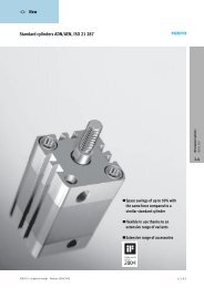
<strong>Compact</strong> <strong>cylinders</strong> <strong>ADN</strong>, <strong>to</strong> <strong>ISO</strong> <strong>21287</strong>Technical dataTechnical data – Variant S1Pis<strong>to</strong>n ∅ 25 40 63 100Pneumatic connection M5 M5 Gx GxPis<strong>to</strong>n rod thread Female M6 M10 M12 M16Male M8 M12x1.25 M16x1.5 M20x1.5Special thread Female M5 M8 M10 –variant K5 Male M10, M10x1.25 M10x1.25, M12 M12x1.25, M16 M16x1.5, M20Operating and environmental conditionsPis<strong>to</strong>n ∅ 12 16 20 25 32 40 50 63 80 100 125Operating mediumFiltered compressed air, lubricated or unlubricatedOperating pressure 1…10 0.6 … 10[bar] Q 1.3 … 10 1…10 0.8 … 10 0.6 … 10S1 – 1…10 – 1…10 – 1…10 – 1…10 –S2, S20 1.5 … 10 1.3 … 10 1.2 … 10 1…10 0.8 … 10S6 1…10 0.6 … 10S11 0.45 … 10 0.25 … 10R8, TT – 1,5 … 10 1 … 10 –Ambient temperature 1) –20 … +80[°C] S6 0 … +120R3 –20 … +80TT – –40 … +80 –Corrosion resistance 2class CRC 2) R3 3ATEXSpecified types www.fes<strong>to</strong>.com1) Note operating range of proximity sensors2) Corrosion resistance class 2 <strong>to</strong> Fes<strong>to</strong> standard 940 070Components subject <strong>to</strong> moderate corrosion stress. Externally visible parts with primarily decorative surface requirements which are in direct contact with a normal industrial environment or media such as coolants orlubricating agentsCorrosion resistance class 3 <strong>to</strong> Fes<strong>to</strong> standard 940 070Components with heavy corrosion exposure. Externally visible components in direct contact with normal industrial atmosphere or media such as solvents and cleaning agents, where the surface requirement ispredominantly functional.Forces [N] and impact energy [J]Pis<strong>to</strong>n ∅ 12 16 20 25 32 40 50 63 80 100 125Theoretical force at 68 121 188 295 483 754 1178 1870 3016 4712 73636 bar, advancing S1 – – – 295 – 754 – 1870 – 4712 –S2 51 90 141 247 415 686 1057 1750 2827 4524 7069Theoretical force at 51 90 141 247 415 686 1057 1750 2827 4524 70696bar,retracting S1 – – – 247 – 633 – 1681 – 4417 –S2 51 90 141 247 415 686 1057 1750 2827 4524 7069Max. impact energy at 0.07 0.15 0.2 0.3 0.4 0.7 1 1.3 1.8 2.5 3.3the end positions S1 – – – 0.3 – 0.7 – 1.3 – 2.5 –S6 0.035 0.075 0.1 0.15 0.2 0.35 0.5 0.65 0.9 1.25 1.75K10 – – 0.16 0.24 0.32 0.56 0.8 1 1.4 2 2.6S20 – 0.016 0.024 0.083 0.15 0.39 0.48 0.62 0.8 0.9 0.95Permissible impact velocity:Maximum permissible load:2xE perm.v perm. = mdead + m loadm load = 2xE perm.v 2− m deadv perm.E perm.m deadm loadPermissible impact velocityMax. impact energyMoving load (drive)Moving work load-H- NoteThese specifications represent themaximum values which can be reached.Note the maximum permittedimpact energy.14 Internet: www.fes<strong>to</strong>.com/catalogue/...Subject <strong>to</strong> change – 2010/02