You also want an ePaper? Increase the reach of your titles
YUMPU automatically turns print PDFs into web optimized ePapers that Google loves.
®M2Direct Digital AmplifierРУССКИЙSVENSKADEUTSCHENGLISHITALIANOESPAÑOLFRANÇAISOwner’s ManualNEDERLANDS
IMPORTANT SAFETY INSTRUCTIONSENGLISH FRANÇAIS ESPAÑOL ITALIANO DEUTSCH NEDERLANDS SVENSKA РУССКИЙSAVE THESE INSTRUCTIONS FOR LATER USE.FOLLOW ALL WARNINGS AND INSTRUCTIONS MARKED ON THEAUDIO EQUIPMENT.1 Read instructions - All the safety and operating instructions should beread before the product is operated.2 Retain instructions - The safety and operating instructions should beretained for future reference.3 Heed Warnings - All warnings on the product and in the operatinginstructions should be adhered to.4 Follow Instructions - All operating and use instructions should befollowed.5 Cleaning - Unplug this product from the wall outlet before cleaning.Do not use liquid cleaners or aerosol cleaners. Use a damp cloth forcleaning.6 Attachments - Do not use attachments not recommended by theproduct manufacturer as they may cause hazards.7 Water and Moisture - Do not use this product near water-for example,near a bath tub, wash bowl, kitchen sink, or laundry tub; in a wetbasement; or near a swimming pool; and the like.8 Accessories - Do not place this product on an unstable cart, stand,tripod, bracket, or table. The product may fall, causing serious injury toa child or adult, and serious damage to the product. Use only with acart, stand, tripod, bracket, or table recommended by the manufacturer,or sold with the product. Any mounting of the product should followthe manufacturer’s instructions, and should use a mounting accessoryrecommended by the manufacturer.9 A product and cart combination should be moved withcare. Quick stops, excessive force, and uneven surfaces maycause the product and cart combination to overturn.10 Ventilation - Slots and openings in the cabinet are provided forventilation and to ensure reliable operation of the product and toprotect it from overheating, and these openings must not be blockedor covered. The openings should never be blocked by placing theproduct on a bed, sofa, rug, or other similar surface. This product shouldnot be placed in a built-in installation such as a bookcase or rack unlessproper ventilation is provided or the manufacturer’s instructions havebeen adhered to.11 Power Sources - This product should be operated only from the typeof power source indicated on the marking label. If you are not sure ofthe type of power supply to your home, consult your product dealer orlocal power company.The primary method of isolating the amplifier from the mains supplyis to disconnect the mains plug. Ensure that the mains plug remainsaccessible at all times. Unplug the AC power cord from the AC outlet ifthe unit will not be used for several months or more.12 Grounding or Polarization - This product may be equipped with apolarized alternating-current line plug (a plug having one blade widerthan the other). This plug will fit into the power outlet only one way.This is a safety feature. If you are unable to insert the plug fully into theoutlet, try reversing the plug. If the plug should still fail to fit, contactyour electrician to replace your obsolete outlet. Do not defeat the safetypurpose of the polarized plug.13 Power - Cord Protection - Power-supply cords should be routed so thatthey are not likely to be walked on or pinched by items placed upon oragainst them, paying particular attention to cords at plugs, conveniencereceptacles, and the point where they exit from the product.14 Outdoor Antenna Grounding - If an outside antenna or cable systemis connected to the product, be sure the antenna or cable system isgrounded so as to provide some protection against voltage surgesand built-up static charges. Article 810 of the National Electrical Code,ANSI/NFPA 70, provides information with regard to proper groundingof the mast and supporting structure, grounding of the lead-in wireto an antenna discharge unit, size of grounding conductors, locationof antenna discharge unit, connection to grounding electrodes, andrequirements for the grounding electrode.NOTE TO CATV SYSTEM INSTALLERThis reminder is provided to call the CATV system installer’s attention to Section820-40 of the NEC which provides guidelines for proper grounding and, inparticular, specifies that the cable ground shall be connected to the groundingsystem of the building, as close to the point of cable entry as practical.15 Lightning - For added protection for this product during a lightningstorm, or when it is left unattended and unused for long periods oftime, unplug it from the wall outlet and disconnect the antenna orcable system. This will prevent damage to the product due to lightningand power-line surges.16 Power Lines - An outside antenna system should not be located in thevicinity of overhead power lines or other electric light or power circuits,or where it can fall into such power lines or circuits. When installing anoutside antenna system, extreme care should be taken to keep fromtouching such power lines or circuits as contact with them might befatal.17 Overloading - Do not overload wall outlets, extension cords, orintegral convenience receptacles as this can result in a risk of fire orelectric shock.18 Object and Liquid Entry - Never push objects of any kind into thisproduct through openings as they may touch dangerous voltage pointsor short-out parts that could result in a fire or electric shock. Never spillliquid of any kind on the product.WARNING: THE APPARATUS SHOULD NOT BE EXPOSED TODRIPPING OR SPLASHING, AND OBJECTS FILLED WITH LIQUIDS,SUCH AS VASES, SHOULD NOT BE PLACED ON THE APPARATUS.AS WITH ANY ELECTRONIC PRODUCTS, USE CARE NOT TO SPILLLIQUIDS INTO ANY PART OF THE SYSTEM. LIQUIDS CAN CAUSE AFAILURE AND/OR A FIRE HAZARD.2
IMPORTANT SAFETY INSTRUCTIONS19 Damage Requiring Service - Unplug this product from the wall outletand refer servicing to qualified service personnel under the followingconditions:a) When the power-supply cord or plug is damaged.b) If liquid has been spilled, or objects have fallen into the product.c) If the product has been exposed to rain or water.d) If the product does not operate normally by following the operatinginstructions. Adjust only those controls that are covered by theoperating instructions as an improper adjustment of other controlsmay result in damage and will often require extensive work by aqualified technician to restore the product to its normal operation.e) If the product has been dropped or damaged in any way.f) when the product exhibits a distinct change in performance-thisindicates a need for service.20 Replacement Parts - When replacement parts are required, besure the service technician has used replacement parts specifiedby the manufacturer or have the same characteristics as theoriginal part. Unauthorized substitutions may result in fire, electricshock, or other hazards.21 Safety Check - Upon completion of any service or repairs to thisproduct, ask the service technician to perform safety checks todetermine that the product is in proper operating condition.22 Wall or Ceiling Mounting - The product should be mounted to a wallor ceiling only as recommended by the manufacturer.23 Heat - The product should be situated away from heat sources such asradiators, heat registers, stoves or other products (including amplifiers)that produce heat.WARNINGTO REDUCE THE RISK OF FIRE OR ELECTRIC SHOCK, DO NOT EXPOSE THISPRODUCT TO RAIN OR MOISTURE.CAUTIONTO PREVENT ELECTRIC SHOCK, MATCH WIDE BLADE OF PLUG TO WIDE SLOT,FULLY INSERT.THE LIGHTNING FLASH WITH ARROWHEAD SYMBOL, WITHINAN EQUILATERAL TRIANGLE, IS INTENDED TO ALERT THE USERTO THE PRESENCE OF UNINSULATED “DANGEROUS VOLTAGE”WITHIN THE PRODUCT’S ENCLOSURE THAT MAYBE OFSUFFICIENT MAGNITUDE TO CONSTITUTE A RISK OF ELECTRICSHOCK TO PERSONS.THE EXCLAMATION POINT WITHIN AN EQUILATERAL TRIANGLE ISINTENDED TO ALERT THE USER TO THE PRESENCE OF IMPORTANTOPERATING AND MAINTENANCE (SERVICING) INSTRUCTIONS INTHE LITERATURE ACCOMPANYING THE APPLIANCE.The equipment draws its nominal non-operational power from the ACoutlet with its POWER switch at the ON position.The socket-outlet shall be installed near the apparatus and shall be easilyaccessible.CAUTIONChanges or modifications to this equipment not expressly approved byNAD Electronics for compliance could void the user’s authority to operatethis equipment.CAUTION REGARDING PLACEMENTTo maintain proper ventilation, be sure to leave a space around the unit(from the largest outer dimensions including projections) that is equal to orgreater than shown below.Left and Right Panels: 10 cmRear Panel: 10 cmTop Panel: 50 cmРУССКИЙSVENSKADEUTSCHITALIANOESPAÑOLFRANÇAISENGLISHNEDERLANDS3
IMPORTANT SAFETY INSTRUCTIONSENGLISH FRANÇAIS ESPAÑOL ITALIANO DEUTSCH NEDERLANDS SVENSKA РУССКИЙNOTES ON ENVIRONMENTAL PROTECTIONAt the end of its useful life, this product must not be disposedof with regular household waste but must be returned to acollection point for the recycling of electrical and electronicequipment. The symbol on the product, user’s manual andpackaging, point this out.The materials can be reused in accordance with their markings. Throughre-use, recycling of raw materials or other forms of recycling of oldproducts, you are making an important contribution to the protection ofour environment. Your local administrative office can advise you of theresponsible waste disposal point.INFORMATION ABOUT COLLECTION AND DISPOSAL OFWASTE BATTERIES (DIRECTIVE 2006/66/EC OF THE EUROPEANPARLIAMENT AND THE COUNCIL OF EUROPEAN UNION) (FOREUROPEAN CUSTOMERS ONLY)Batteries bearing any of these symbols indicatethat they should be treated as “separate collection”and not as municipal waste. It is encouraged thatnecessary measures are implemented to maximizethe separate collection of waste batteries andto minimize the disposal of batteries as mixedmunicipal waste.End-users are exhorted not to dispose wastebatteries as unsorted municipal waste. In order toachieve a high level of recycling waste batteries, discard waste batteriesseparately and properly through an accessible collection point in yourvicinity. For more information about collection and recycling of wastebatteries, please contact your local municipality, your waste disposal serviceor the point of sale where you purchased the items.By ensuring compliance and conformance to proper disposal of wastebatteries, potential hazardous effects on human health is prevented andthe negative impact of batteries and waste batteries on the environmentis minimized, thus contributing to the protection, preservation and qualityimprovement of the environment.RECORD YOUR MODEL NUMBER (NOW, WHILE YOU CAN SEE IT)The model and serial number of your new M2 are located on the back ofthe cabinet. For your future convenience, we suggest that you record thesenumbers here:Model no: ......................................Serial no.: . . . . . . . . . . . . . . . . . . . . . . . . . . . . . . . . . . . . . .NAD is a trademark of NAD Electronics International, a division of Lenbrook Industries LimitedCopyright 2012, NAD Electronics International, a division of Lenbrook Industries Limited4
INTRODUCTIONGETTING STARTEDQUICK STARTIn case you simply cannot wait to experience the performance of your newNAD M2 Direct Digital Amplifier, we provide the following QUICKSTARTinstructions to get you underway.Please make all the connections to your M2 with the unit unpluggedfrom the AC outlet. It is also advisable to power-down or unplug allassociated components while making or breaking any signal or AC powerconnections.1 Connect your speakers to the LEFT and RIGHT speaker terminals andinput sources to the applicable M2 rear panel input sockets.WARNINGThe M2 employs a “floating” ground design. External devices (such asspeaker switching or headphone adaptors) that connect the left andright channels together must not be used with the M2. Left and rightchannels must never be connected to each other.2 Make sure that the OFF/AUTO trigger switch at the M2 rear panel is setto OFF. Connect the AC cord to M2’s AC Mains input and then plug intoan AC outlet.WARNINGFor optimal performance, the M2 requires a grounded AC receptacle or aseparate earth ground. Ensure the proper grounding of your system.3 Set the rear panel POWER switch to the “ON” position. The Standby LEDwill illuminate amber (standby mode).SAVE THE PACKAGINGPlease save the box and all of the packaging in which your M2 arrived.Should you move or otherwise need to transport your M2, this is by far thesafest container in which to do so. We’ve seen too many otherwise perfectcomponents damaged in transit for lack of a proper shipping carton, soplease: Save that box!NOTES ON INSTALLATIONYour NAD M2 should be placed on a firm, level surface. Avoid placing theunit in direct sunlight or near sources of heat and damp. Allow adequateventilation. Do not place the unit on a soft surface like a carpet. Do notplace it in an enclosed position such a bookcase or cabinet that mayimpede the air-flow through the ventilation slots. Make sure the unit isswitched off before making any connections.Use high quality leads and sockets for optimum performance and reliability.Ensure that leads and sockets are not damaged in any way and all socketsare firmly pushed home. For best performance, use quality speaker leads of16 gauge (1.5mm) thickness or more.Should water get into your NAD M2, shut off the power to the unit andremove the plug from the AC socket. Have the unit inspected by a qualifiedservice technician before attempting to use it again.DO NOT REMOVE THE COVER; THERE ARE NO USER-SERVICEABLEPARTS INSIDE.ITALIANOESPAÑOLFRANÇAISENGLISH4 Press the front panel STANDBY button to turn ON the M2. The StandbyLED indicator will turn from amber to blue and illuminate the VFD.5 Press the corresponding front panel input button of your preferredsource input.DEUTSCHРУССКИЙSVENSKANEDERLANDS5
IDENTIFICATION OF CONTROLSFRONT PANELENGLISH FRANÇAIS ESPAÑOL ITALIANO DEUTSCH NEDERLANDS SVENSKA РУССКИЙ11 STANDBY LED: This indicator will light up amber when M2 is instandby state. When M2 is at ON state, this indicator will illuminate blue.2 STANDBY BUTTON: Press this button to switch ON the M2. TheStandby LED indicator will turn from amber to blue and illuminate theVFD. Pressing the STANDBY button again turns the unit back to standbymode.IMPORTANT NOTICEThe rear panel POWER switch must be set to ON position for theSTANDBY button to activate. After pressing the STANDBY button, therewill be a delay before the M2 will be completely enabled. Please waituntil the initial “NAD M2” display in the VFD is extinguished before youselect any of the source input or features of your M2.3 VACUUM FLUORESCENT DISPLAY (VFD): Display visual informationabout the selected source input, menu options, volume level and otherrelated information and settings.4 VOLUME: Use this control to adjust M2’s overall amplification or volumelevel. Turn clockwise to increase the volume setting; counter clockwiseto lower it. The M2 features a “velocity sensing” volume control; rapidmovement changes the volume in large steps, slow movement incrementsthe volume in 0.5dB steps. The VOLUME knob is also used to select optionsor adjust settings when MENU button is activated.5 COAX 1: Select the source connected to the COAX 1 rear panelterminal as the active input.6 COAX 2: Select the source connected to the COAX 2 rear panelterminal as the active input.25 6 7 87 OPTICAL 1: Select the source connected to the OPTICAL 1 rear panelterminal as the active input.8 OPTICAL 2: Select source connected to the OPTICAL 2 rear panelterminal as the active input.9 AES/EBU: Select the source connected to the AES/EBU IN rear panelconnector as the active input.39 10 11 12 1310 BALANCED: Select the source connected to the BALANCED L andBALANCED R rear panel connectors as the active input.11 SINGLE-ENDED: Select the source connected to the SINGLE-ENDED Land SINGLE-ENDED R rear panel terminals as the active input.12 LOOP (DIGITAL PROCESSOR LOOP): Allow the insertion of externaldigital filters into the signal path. This is the digital equivalent of theanalog “Tape Monitor Loop”. An example on how to take advantage ofthis feature is illustrated below.a Connect a digital input to the rear panel’s OPTICAL 1 TosLink opticalterminal.b Connect the rear panel’s OPTICAL LOOP OUT to a compatibleOPTICAL IN of a Mac or any processor where the signal can besubjected to a wide library of crossover filters, equalization or roomcorrection programs (Check if your Mac or processor has thesefeature capabilities).c Send out the processed signal from your Mac or processor’scorresponding Optical Out port into M2’s OPTICAL LOOP IN therebycompleting the signal loop path.d Press front panel’s “loop” button to select your OPTICAL 1’s“processed” input signal. When “loop” feature is engaged, “LOOP” willbe continuously displayed at the lower left corner of the VFD after abrief display of sample rate setting of the source.IMPORTANT NOTICEWith “loop” button enabled, there will be no audio output if anyconnection from the above “loop” setup example is “broken” (i.e., noconnection to OPTICAL OUT, not looped to “OPTICAL LOOP IN”, etc). Press“loop” button again to deactivate or turn off the “loop” feature (“LOOP”is extinguished in the VFD) thus returning to normal audio listening of aselected source input.NOTEThis digital processor loop feature can be applied to all analog anddigital audio input signal sources (Optical 1-2, Coax 1-2, AES/EBU,BALANCED and SINGLE-ENDED).46
IDENTIFICATION OF CONTROLSFRONT PANEL13 MENU: Toggle to view the available options such as LEVEL TRIM andSAMPLE RATE options for BALANCED and SINGLE-ENDED input signalas well as selections for SPEAKER COMPENSATION and POLARITY. Thesemenu options are accessed by pressing the MENU button and thenrotating the VOLUME control knob clockwise or counterclockwise toselect desired level or setting. Release the VOLUME knob when youreach your preferred level or setting. The change will take effect after afew seconds when the display returns to show the default information(selected input and volume setting). Press MENU button again to selectanother menu option.LEVEL TRIM: Adjust the BALANCED or SINGLE-ENDED input signal levelfrom -9dB to 0dB or FIXED.-9dB to 0dB: Increase or decrease the input signal level from -9dBto 0dB. This attenuates the signal before the Analog-to-Digital (A/D)Converter. If the analog input signal sounds distorted, the inputshould be attenuated.NOTEAttenuating too much can reduce the potential resolution of the A/DConverter.FIXED: This setting should be selected when M2 is connectedto the output of a preamplifier and is used primarily as a poweramplifier. Output level is fixed and the M2’s Volume Control isbypassed. Adjust the level using the source signal’s preamplifiervolume or input level control.NOTEVOLUME control is bypassed and cannot be adjusted when LEVEL TRIMis set to “FIXED” setting. The corresponding VOLUME level (in dB) will notappear in the VFD; what will be shown instead is “VOL FIXED”. Set LEVELTRIM to any other level except “FIXED” to adjust VOLUME control todesired level.SAMPLE RATE (48 kHz, 96 kHz, 192 kHz): Select the user’spreference for sample rate of the A/D Converter. Higher samplingrates allow for anti-aliasing filters to take effect further outside theaudible frequency range and are generally considered to soundbetter, especially in the high frequencies. You may need to reducethe sampling rate if you are using the Digital Processor Loop, as manyexternal devices will not operate at 96 kHz or 192 kHz.SPEAKER COMPENSATION (2 Ohms, 4 Ohms, 5 Ohms, 6 Ohms,7 Ohms, 8 Ohms, >8 Ohms): Digital impedance compensation filterallows fine tuning of the top octave to match the speaker impedance.This will result in perfectly flat frequency response at 20 kHz. Theeffect of this filter may not be audible* but it is measurable, and itcompensates for the small effect of the digital reconstruction filter thateliminates the 288 kHz sampling frequency of the amplifier.*The exception may be some electrostatic speakers that have very lowimpedance at high frequency. The lower the HF impedance, the greaterthe deviation from flat response.POLARITY (POSITIVE, REVERSED): Allow compensation forrecordings that have reversed polarity.Positive: A positive sine wave at the input remains positive at theoutput.Reversed: A positive sine wave at the input is negative (inverted) orreversed at the output.IMPORTANT NOTICEFor all of the above menu options, a chosen option or level setting willnot immediately take effect upon selection. There will be a slight delay orpause before the corresponding action or response is realized.RENAMING A SOURCE INPUTA particular source input can be renamed according to your preference.You can use up to 20 characters in renaming a source input. Below is theprocedure on how to rename a source input.Example: Rename “DIGITAL OPTICAL 1” to “BD PLAYER”.1 Press the front panel “optical 1” button to select “DIGITAL OPTICAL1” input. Then, press and hold the front panel “optical 1” button until“DIGITAL OPTICAL 1” is shown in the lower section of the VFD and with“D” flashing (Note that “DIGITAL OPTICAL 1” is also shown at uppersection of the VFD).2 Within 5 seconds, rotate the VOLUME control knob clockwise orcounterclockwise to select the first character (“B” from the alphabeticallist). The ranges of characters available are 0-9, _ (space) and A-Z.3 Press the front panel “loop” button to select the character and at thesame time move on to the next character. Repeat steps 2 and 3 foreach character in sequence.4 Complete the renaming process by pressing the front panel “menu”button to save the new source input name.NOTES• Renaming of a source input can only be done using the front panel buttons.• If no change is made within 5 seconds or if the front panel button of thesource input being renamed is pressed, the renaming process will beautomatically terminated with any renamed characters made not saved.• You can terminate the renaming process by pressing any other frontpanel buttons (except “loop”, “menu” or the current source input beingrenamed). The renamed characters at the time of terminating theprocess will be saved.РУССКИЙSVENSKANEDERLANDSDEUTSCHITALIANOESPAÑOLFRANÇAISENGLISH7
IDENTIFICATION OF CONTROLSREAR PANELENGLISH FRANÇAIS ESPAÑOL ITALIANO DEUTSCH NEDERLANDS SVENSKA РУССКИЙ1 2 3 4 5 6 7 8 9 10 11 12 13 14 1516 17 18ATTENTION!Please make sure that the M2 is powered OFF or unplugged before making any connections. It is also advisable to power-down or unplug all associatedcomponents while making or breaking any signal or AC power connections.1 BALANCED: Connect XLR audio source to these connectors. Ensurethat proper pin configurations are followed – Pin 1: Ground, Pin 2:Positive (signal live) and Pin 3: Negative (signal return).2 SINGLE-ENDED: Use a twin RCA-to-RCA lead to connect to thesesockets the left and right analog output of a CD player, preamplifier orprocessor.3 DIGITAL AUDIO (COAX 1-2): Connect to the corresponding coaxial S/PDIF-format digital output of sources such as SACD/CD players, HDTV orsatellite tuners and other components.DIGITAL AUDIO OUT (COAXIAL OUT): Connect COAXIAL OUT to thecorresponding S/PDIF digital input of compatible devices such as CDrecorders, receivers, computer soundcard or other digital processors.4 DIGITAL AUDIO (OPTICAL 1-2): Connect to the corresponding opticalS/PDIF-format digital output of sources such as SACD/CD players, HDTVor satellite tuners and other components.IMPORTANT NOTICEFor high-end sources with higher sampling rates like 176kHz and192kHz, it is highly recommended that such sources be interfacedwith the AES/EBU IN connector. The AES/EBU IN is well suited to handlesources with ultra-high sampling rates.5 DIGITAL AUDIO OPTICAL LOOP (OPTICAL LOOP OUT, OPTICALLOOP IN): Connect OPTICAL LOOP OUT to the corresponding S/PDIFdigital input of compatible devices such as CD recorders, receivers,computer soundcard or other digital processors. This OPTICAL LOOPOUT terminal is the same digital output that can be fed to a Mac orprocessor where the signal can be subjected to a wide library of thirdparty crossover filters, equalization or room correction programs.The processed signal from the Mac or processor is then sent outthrough their corresponding Optical Out port into M2’s OPTICAL LOOPIN thereby completing the signal loop path.Refer also to the item above about “LOOP (DIGITAL PROCESSOR LOOP)”under IDENTIFICATION OF CONTROLS – FRONT PANEL.6 AES/EBU IN: Digital audio stream from professional audio sources likeSACD/CD Players or processors can be connected to this XLR connector.For high-end sources with higher sampling rates like 176kHz and192kHz, it is highly recommended that such sources be interfaced withthe AES/EBU IN connector. The AES/EBU IN is well suited to handle suchsources with high sampling rate.7 DIGITAL SOFT CLIPPING: Enables NAD’s proprietary Soft Clippingcircuitry on all channels. At ON position, Soft Clipping gently limits theoutput of the M2 to minimize audible distortion should the amplifier beover-driven. Soft Clipping may simply be left ON at all times to reducethe likelihood of audible distortion from excessive volume settings.However, for critical listening and to preserve optimum dynamics, youmay wish to defeat it by setting this switch to “OFF” position.8 OFF/AUTO TRIGGER SWITCH: When at AUTO position, the front panelSTANDBY button is disabled and M2 remote control’s [ON/OFF] buttonnon-functional. At this condition, the M2 can only be switched ON fromstandby mode or back to standby mode when +12V DC is applied orcut off at the +12V TRIGGER IN jack. Slide the OFF/AUTO switch to OFFsetting for the M2 to be normally switched ON (or back to standbymode) using the front panel STANDBY button or M2 remote control’s[ON/OFF] button.NOTEThe rear panel POWER switch must be set to ON position for theSTANDBY button to activate. Switch the rear panel POWER switch to ONposition in order to make use of the +12V TRIGGER IN and OFF/AUTOTRIGGER SWITCH features as well as the front panel STANDBY button.8
IDENTIFICATION OF CONTROLSREAR PANEL9 +12V TRIGGER IN: This input allows the M2 to be switched remotelyto standby mode or ON by ancillary equipment, such as an amplifier,preamp, AV processor, etc. The controlling device must be equippedwith a 12 V trigger output to use this feature.10 +12V TRIGGER OUT: The +12V TRIGGER OUT is used for controllingexternal equipment that is equipped with a +12V trigger input. Thisoutput will be 12V when the M2 is ON and 0V when the unit is eitherOFF or in standby mode.11 RIGHT SPEAKERS: Connect the right speaker to the terminals marked“R +” and “R-” ensuring that the “R+” is connected to the “+” terminalon your loudspeaker and the “R-” is connected to the loudspeaker’s “-”terminal. There are two sets of RIGHT SPEAKER outputs and these areidentical in function (parallel connection) and are provided for ease ofBi-wiring with heavy audiophile cables. Double check your speakerconnections before powering up the M2.Always use heavy duty (16 gauge; 1.5mm, or thicker) stranded wireto connect loudspeakers to your M2. The high-current binding postterminals can be used as a screw terminal for cables terminating inspade or pin sockets or for cables with bare wire ends.BI-WIRINGMost modern high quality loudspeakers offer the option of Bi-wiring.This separates the HF crossover from the LF crossover and offersenhanced performance by preventing LF return currents from affectingthe HF performance. If you decide to bi-wire, be sure to remove the“links” at the loudspeaker that connect the LF and HF sections (these areprovided for convenience when single wire connection is used). Yourloudspeaker instruction manual should cover this subject as well.WARNINGThe M2 employs a “floating” ground design. External devices (such asspeaker switching or headphone adaptors) that connect the left andright channels together must not be used with the M2. Left and rightchannels must never be connected to each other.12 POWER SWITCH: The POWER switch supplies the master AC mainspower for the M2. When this switch is at ON position, the M2 is instandby mode as shown by the amber status condition of the standbyLED. Toggle the front panel’s STANDBY button to switch ON the M2 orback to standby mode. If you intend not to use the M2 for long periodsof time (such as when on vacation), switch the POWER switch to theOFF position. When the POWER switch is at OFF position, the frontpanel STANDBY button or M2 remote control cannot activate the M2.13 AC MAINS INPUT: The M2 comes supplied with a separate AC Mainscable. Before connecting the cable to a live wall socket ensure thatit is firmly connected to the M2’s AC Mains input socket first. Alwaysdisconnect the AC Mains cable plug from the live wall socket first,before disconnecting the cable from the M2’s Mains input socket.14 FUSE HOLDER: In the unlikely event a fuse may need to be replaced,unplug the AC cord from the wall. Disconnect also the AC cord fromM2’s AC Mains input socket. Then, remove all connections from theamplifier. Use a flathead screw or similar to open the fuse holder via theslot located on the top edge of the fuse holder. With the screw driverin place, push it outward to unlatch and open the fuse holder. Onlyreplace the fuse with the same type, size, and specification.IMPORTANT NOTICEDo not use any substitute fuses of different types, ratings or values.Failure to observe this precaution may cause damage to the amplifiercircuits and may create a fire hazard and/or defeat the safety built intothe M2 thus voiding the warranty.15 LEFT SPEAKERS: Connect the left speaker to the terminals marked “L+” and “L-” ensuring that the “L+” is connected to the “+” terminal on yourloudspeaker and the “L-” is connected to the loudspeaker’s “-” terminal.There are two sets of LEFT SPEAKER output and these are identical infunction (parallel connection) and are provided for ease of Bi-wiringwith heavy audiophile cables. Refer also to “RIGHT SPEAKERS” above.16 RS-232: Connect this interface via RS-232 serial cable (not supplied)to any Windows® compatible PC to allow remote control of the M2through NAD’s proprietary PC software or other compatible externalcontrollers. NAD is a certified partner of AMX, Control4, Crestron andSavant and fully supports these external devices. See your NAD audiospecialist for more information.17 IR IN: This input is connected to the output of an IR (infrared) repeater(Xantech or similar) or the IR output of another component to allowcontrol of M2 from a remote location.18 GROUND TERMINAL: The M2 requires a grounded AC receptacle or aseparate earth ground. Use this terminal to properly ground your M2. Aground lead wire or similar can be used to connect the M2 to groundvia this ground terminal. After insertion, tighten the terminal to securethe lead.BARE WIRES AND PIN CONNECTORSBare wires and pin connectors should be inserted into the hole in the shaftof the terminal. Unscrew the terminal’s bushing until the hole in the screwshaft is revealed. Insert the pin or bare cable end into the hole and securethe cable by tightening down the terminal’s bushing. Avoid any dangerof bare metal from the cables touching the rear panel or another connector.SPADE CONNECTORSThese should be slotted under the terminal’s screw bushing, which is thenfully tightened. Ensure the connector is tightly secured and there is nodanger of bare metal from spade connectors touching the rear panel oranother connector as this may cause damage.РУССКИЙSVENSKANEDERLANDSDEUTSCHITALIANOESPAÑOLFRANÇAISENGLISH9
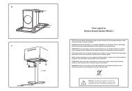
IDENTIFICATION OF CONTROLSREAR PANELENGLISH FRANÇAIS ESPAÑOL ITALIANO DEUTSCH NEDERLANDS SVENSKA РУССКИЙEXAMPLE ILLUSTRATION OF GROUNDING THE M2VIA THE REAR PANEL GROUND TERMINALNOTES• The above illustration shows the M2 being connected to ground viaa metal water pipe. There maybe other grounding conductor pointsin your home. Consult with a licensed electrician to properly locateor correctly install a grounding conductor in your home. NAD is notresponsible for any malfunction, damage or costs associated with theinstallation, connection or grounding of your M2.• The grounding wire is not supplied with your M2.DIGITAL POWERDRIVEThe M2 uses NAD’s proprietary Digital PowerDrive amplifier technologythat allows substantial additional power for short periods of time. Researchhas shown that the peak to average power required to faithfully reproducemusic can be a factor of ten for well recorded performances. DigitalPowerDrive uniquely satisfies this requirement. Music sounds moredynamic and “open” with PowerDrive because the musical transients that arepresent in a live performance are not reduced in amplitude or “compressed”.10
IDENTIFICATION OF CONTROLSM2 REMOTE CONTROL121 ON: Switch M2 ON.2 OFF: Switch M2 OFF.ENGLISH3 COAX 1-2, OPT 1-2, AES/EBU: Select Coaxial, Optical or AES/EBU digital source input.344 PRO LOOP: Activate or deactivate “loop” feature.55 BALANCED: Select BALANCED source input.SINGLE-ENDED: Select SINGLE-ENDED source input.6 MUTE: Temporarily shuts down audio output.FRANÇAIS67 DIM: Reduce or restore VFD brightness.7 88 VOL : Increase or decrease the loudness level.9 DEVICE SELECTOR 1-2: Switch betweenDVD and CD control functions. Set to position“1” for applicable CD control button functions- compatible with NAD models like C 515BEE,C 545BEE, C 565BEE and M5. Set to position “2”for applicable DVD control button functions -compatible with NAD models like T 535, M55,T 585 and DVD section of L 54, VISO FIVE andVISO TWO.9ESPAÑOLITALIANOCD PLAYER CONTROL (for use with compatible NAD CD or SACD/CD Players) : Set the DEVICESELECTOR to “1” in order to gain access to these buttons.REPEAT: Repeat track, file or whole disc.RANDOM: Play tracks or files in random mode.: Open or close disc tray.: Stop playback.: Pause playback temporarily.: Go to beginning of current/previous track or file.: Start playback.: Go to next track or file.DEUTSCHNEDERLANDSDVD PLAYER CONTROL (for use with compatible NAD DVD Players) : Set the DEVICE SELECTORto “2” in order to gain access to these buttons.TITLE: Display DVD title menu.MENU: Access menu on a DVD disc.DISP: Access on-screen display.RTN: Exit from a menu window.: Select an item in a menu.ENTER: Acknowledge menu selection.: Open or close disc tray.: Stop playback.: Pause playback temporarily.: Go to the beginning of current/previous track, file or chapter.: Start playback.: Go to next track, file or chapter..SVENSKAРУССКИЙ11
www.NADelectronics.com©2012 NAD ELECTRONICS INTERNATIONALA DIVISION OF LENBROOK INDUSTRIES LIMITEDAll rights reserved. NAD and the NAD logo are trademarks of NAD Electronics International, a division of Lenbrook Industries Limited.No part of this publication may be reproduced, stored or transmitted in any form without the written permission of NAD Electronics International.While every effort has been made to ensure the contents are accurate at the time of publication, features and specifications may be subject to change without prior notice.M2_eng_OM_v12 - May 2012