Rinnai Energy Saver Flue Manual - Pivot Stove & Heating
Rinnai Energy Saver Flue Manual - Pivot Stove & Heating
Rinnai Energy Saver Flue Manual - Pivot Stove & Heating

Create successful ePaper yourself
Turn your PDF publications into a flip-book with our unique Google optimized e-Paper software.
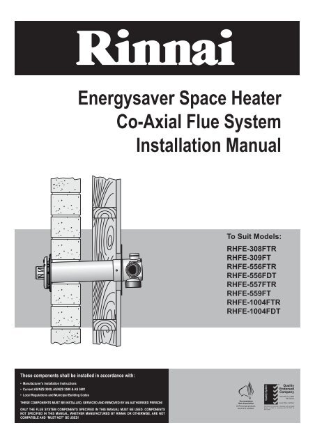
<strong>Energy</strong>saver Space HeaterCo-Axial <strong>Flue</strong> SystemInstallation <strong>Manual</strong>To Suit Models:RHFE-308FTRRHFE-309FTRHFE-556FTRRHFE-556FDTRHFE-557FTRRHFE-559FTRHFE-1004FTRRHFE-1004FDTThese components shall be installed in accordance with:• Manufacturer’s Installation Instructions• Current AS/NZS 3000, AS/NZS 3500 & AS 5601• Local Regulations and Municipal Building CodesTHESE COMPONENTS MUST BE INSTALLED, SERVICED AND REMOVED BY AN AUTHORISED PERSON!ONLY THE FLUE SYSTEM COMPONENTS SPECIFIED IN THIS MANUAL MUST BE USED. COMPONENTSNOT SPECIFIED IN THIS MANUAL, WHETHER MANUFACTURED BY RINNAI OR OTHERWISE, ARE NOTCOMPATIBLE AND “MUST NOT” BE USED!
CONVENTIONS USED IN THIS MANUALThe following symbols are used to highlight specific requirements during installation steps.CLEARANCESWhere required clearances will be provided and must be observed.FALLEnsure that the specified 2° fall is maintained to either the terminal or condensate trap.MEASURERequired measurements will be provided and MUST BE observed for correct installation.CUTCut as required to the specified measurements.FINISHEnsure that burrs and swarf are removed from all cut ends.DISCARDDenotes items that are not required for the specific installation.OBSERVE CORRECT ORIENTATIONWhere specified ensure that components are installed with the correct vertical or horizontalorientation.LUBRICATEUse the supplied container of silicon grease to lubricate components.lubricants as these may damage the flue components.DO NOT use otherSECUREWhere specified secure components with either installer provided or component supplied fixings.DO NOTFailure to observeinjury or death.DO NOT instructions will void the warranty of an appliance and may cause!NOTE / IMPORTANTImportant notes or general hints and guides provided to ease the installation.!CAUTIONCaution notes and or warnings that MUST BE observed for safe and correct installations.The heater and the flue system shall be installed in accordance with the following:<strong>Rinnai</strong> Australia 1 ES <strong>Flue</strong> Installation <strong>Manual</strong>
REGULATIONS, CLEARANCES & GENERAL INFORMATION• The requirements of the current version of AS 5601 (Gas Installations)Note that AS 5601-2004 is referred to in this instruction and was current at the time of printing, but may havesince been superseded. It is the Installer’s responsibility to ensure that requirements of the current version ofAS 5601 are met.• Manufacturers installation instructions.Before commencing an installation, read the installation sections of the ‘Customer and Installation <strong>Manual</strong>’supplied with the heater.• Local & Municipal building codes.• Any other relevant Statutory Regulation.• <strong>Rinnai</strong> <strong>Energy</strong>saver space heater when correctly installed with <strong>Rinnai</strong> approved flue components are roomsealedappliances and no internal ventilation is required.• <strong>Rinnai</strong> <strong>Energy</strong>saver space heater is fan-assisted. Therefore the fan assisted flue clearance dimensions fromAS 5601 extract shown on this page must be used.• The outer plastic section of the Co-Axial flue complies with temperature hazard requirements and can beinstalled with zero clearance to combustible material.• Vertical clearances when using a roof terminal (ESROOFCOWL) are shown in Fig.1.If in doubt contact the <strong>Rinnai</strong> Australia Technical Advice Helpline (number on the back page).ESROOFCOWLMinimum Clearance 500 mmDecktite or lead collar flashing<strong>Flue</strong> pipe clip supplied with ESROOFCOWL<strong>Flue</strong> pipe clip supplied with ESPIPE900ESPIPE900ESPLATEVertical Clearances Fig.1Horizontal Clearances (Extract AS 5601-2004 5.13.6.5 Fig. 5.3)<strong>Rinnai</strong> Australia 2 ES <strong>Flue</strong> Installation <strong>Manual</strong>
REGULATIONS, CLEARANCES & GENERAL INFORMATIONFLUE TRANSITION CONNECTIONS3215 42325 4135411 <strong>Flue</strong> exhaust connection to heater. 2 Combustion air inlet connection to heater (Right hand ~ Small connectionfor models 308, 309, 556, 557, 559 heaters. Left hand ~ Large connection for model 1004 heaters). 3 Rubbercombustion air inlet cap (when fitted) is designed to fit both the large and small combustion air inlet and MUSTcover the air inlet not in use. 4 Combustion air inlet. 5 Exhaust outlet.LOCATIONThis appliance is NOT suitable for inbuilt installations.This appliance MUST NOT be installed where curtains or other combustible materials could come into contact withit. In some cases curtains may need restraining.Heat emanating from the frontof this appliance may over timeaffect the appearance of somematerials used for flooring suchDO NOTas carpet, vinyl, cork or timber.This effect may be amplified ifthe air in the room containscooking vapours or cigarettesmoke. To avoid this possibility,it is recommended that a mat beplaced in front of the appliance,extending at least 750mm infront of it.The flue terminal MUST BE positioned away from flammable materials.In areas subject to heavy snowfall, keep snow clear of flue terminal at all times.• DO NOT flue into naturaldraught flues or fireplaces.• DO NOT flue into otherrooms, roof spaces or intounder floor spaces.• DO NOT Install the heater inan unusually dusty area.IMPORTANTFor other important information regarding the location of the heater refer to the instructionssupplied with the appliance.LUBRICATING INNER PIPE COMPONENTSThe inner flue pipe joints are sealed with an “O” ring seal.To help ensure a good seal and to ease assembly, a small tub of silicone grease is provided with the Direct <strong>Flue</strong>Kit (ESDFK) and the In-Wall Transition Kit (ESKIT03). Use this silicone grease to lubricate the “O” ring on the innerpipes prior to assembly.CAUTIONUse ONLY the supplied silicone based “O Ring” seal lubricant.DO NOT use petroleum based lubricants such as petroleum jelly. Petroleum jelly or similarpetroleum based lubricants will cause deterioration of the “O” ring seals.<strong>Rinnai</strong> Australia 3 ES <strong>Flue</strong> Installation <strong>Manual</strong>
INSTALLATION CONFIGURATIONSThe following configurations are currently available. For alternative configurations contact <strong>Rinnai</strong>.DIRECT/EXTENDEDComponentsOption A (Direct) Option B (Direct Extended)Direct <strong>Flue</strong> Kit ESDFK Direct <strong>Flue</strong> KitCo-Ax Pipe 900mm (Optional) #ESDFKESPIPE900SIDEWAYS Components Back Cover Kit DepthDirect <strong>Flue</strong> KitCo-Ax Pipe 900mm #Back Cover KitESDFKESPIPE900(refer page 8 for Kitcontents)3083095565575591004ESBSKAESBSKEESBSKBESBSKCESBSKFESBSKD200 mm205 mm200 mm200 mm205 mm200 mmA Back Cover Kit is required when the flue system is installedin a sideways configuration.EXTERNAL WALLComponentsOption A (Vertical Termination) Option B (On Wall Termination)Direct <strong>Flue</strong> KitCo-Ax Pipe 900mm #Bend (2 x 45º)Condensate TrapRoof CowlESDFKESPIPE900ESBENDESCONDKESROOFCOWLDirect <strong>Flue</strong> KitCo-Ax Pipe 900mm #Bend (45º) x2Condensate TrapWall Terminal KitESDFKESPIPE900ESBENDESCONDKESWTKITIN-WALLComponentsOption A (Direct)Option B (Offset)Vertical Adaptor Kit §Co-Ax Pipe 900mm #Roof CowlESKIT03ESPIPE900ESROOFCOWLVertical Adaptor Kit §Co-Ax Pipe 900mm #Bend (45º) x2Roof CowlESKIT03ESPIPE900ESBENDESROOFCOWLUNDER FLOOR Components Back Cover Kit DepthDirect <strong>Flue</strong> KitCo-Ax Pipe 900mm #Bend (2 x 45º)Wall Terminal KitBack Cover KitESDFKESPIPE900ESBENDESWTKIT(refer page 8 for Kitcontents)3083095565575591004ESBSKAESBSKEESBSKBESBSKCESBSKFESBSKD200 mm205 mm200 mm200 mm205 mm200 mmA Back Cover Kit is required when the flue system is installedin a under floor configuration.# Order lengths as required § Includes Condensate Trap (ESCONDK)<strong>Rinnai</strong> Australia 4 ES <strong>Flue</strong> Installation <strong>Manual</strong>
INSTALLATION CONFIGURATIONS•DIRECTWhen cutting the flue transitionfor joining to other componentsthe minimum total length is notto be less than 300mm!DIRECT• DIRECT EXTENDED• UNDER FLOOR•SIDEWAYSWhen cutting the flue transitionfor joining to other componentsthe minimum total length is notto be less than 300mm!UNDER FLOOR• DIRECT EXTENDED• EXTERNAL WALL• IN-WALLWhen cutting the flue transitionfor joining to other componentsthe minimum total length is notto be less than 300mm!EXTERNALWALLDIRECTEXTENDEDIN-WALLSIDEWAYS<strong>Rinnai</strong> Australia 5 ES <strong>Flue</strong> Installation <strong>Manual</strong>
WALL PENETRATIONSIt is critical that any wall penetrations are located correctly.CAUTIONEnsure there are no wall studs, noggins, wiring or other obstruction within the wall cavity wherethe flue is proposed to penetrate.Ensure the location of the flue terminal can comply with the requirements of AS 5601. Figure 5.3from AS 5601-2004 and additional information is shown on page 2.Especially relevant is the requirement to have a minimum of 300mm clearance between the flueterminal and the finished ground level. It is not permissible to excavate a hole to obtain therequired 300mm clearance, unless there is sufficient drainage provision.iii1. Select the desired location i for the <strong>Energy</strong>saver Heater.2. Find the vertical centre line of the appliance ii and mark thislocation on the wall.iiiBA3. Using Measurements A & B from Table 1, mark off the arc centreiii on the wall.IMPORTANTThe arc centre iii corresponds to the pivot point centreof the telescopic flue elbow on the heater.The RHFE-308 and RHFE-309 have a fixed length nontelescopicflue elbow. Hence accurate marking of thepenetration arc and associated area are thereforeespecially critical.iiiiGiiviv4. From the arc axis iii use the measurements C, D & E from Table1. to draw an arc on the wall.The lower end point of the arc iv will be the lower limit of theminimum horizontal and vertical centre of penetration G.The upper end point of the arc v will the be the upper limit of theminimum horizontal and vertical centre of penetration G.CDEiiiiiiGviivi5. From the arc axis iii use the measurements F, D & E from Table1. to draw an arc on the wall.The lower end point of the arc vi will be the lower limit of themaximum horizontal and vertical centre of penetration G.The upper end point of the arc vii will be the upper limit of themaximum horizontal and vertical centre of penetration G.FDEIMPORTANTDue to the fixed length non-telescopic flue elbow of theRHFE-308 and RHFE-309 model heaters measurementsC & F are the same for these model only.viii6. The penetration may be made anywhere within the confines ofthe shaded minimum and maximum areas viii defined by the twoarcs.<strong>Rinnai</strong> Australia 6 ES <strong>Flue</strong> Installation <strong>Manual</strong>
WALL PENETRATIONSBelow are diagrams and associated dimension tables for wall penetrations for each <strong>Energy</strong>saver heater model.RHFE 308 RHFE 309iiiiiiGiiiGiiiC & FC & FBADEBADERHFE 556 RHFE 559IiiiIFGiiiiiiCiiBCFADEBADERHFE 557 RHFE 1004iiiiiiGGiiiiiiBFCADEBCFADEAll dimension are in millimetres RHFE 308 RHFE 309 RHFE 556 RHFE 557 RHFE 559 RHFE 1004i Width of appliance 426 465 750 550 760 930ii Centre-Line of appliance 213 233 375 275 380 465iii Arc axis (Axis point of the flue elbow) — — — — — —A Horizontal distance from Centre-Line to arc centre 110 100 220 172 217 305B Vertical distance from base to arc centre 265 265 215 264 247 165C Minimum horizontal limit of arc 150 150 240 200 240 325D Minimum vertical limit of arc 265 120 215 264 120 250E Maximum vertical limit of arc 415 410 310 390 440 340F Maximum horizontal limit of arc 150 150 300 230 305 365G Penetration diameter 100 100 100 100 100 100Table 1.<strong>Rinnai</strong> Australia 7 ES <strong>Flue</strong> Installation <strong>Manual</strong>
FLUE KIT COMPONENTSESDFK(Direct <strong>Flue</strong> Kit)External Wall PlateInternal Wall PlateESFKITIW(In-Wall Transition,<strong>Flue</strong> & Cowl Kit)Top Plate BracketPipe Locating Spacer<strong>Flue</strong> TerminalDrain TubeWall Spacer PlateThis <strong>Manual</strong>Silicon Grease<strong>Flue</strong> TransitionLeft Vermin Plate<strong>Flue</strong> Transition /Condensation Trap22mmx67mmx2Mounting/Securing ScrewsESKIT03(In-Wall Transition Kit)This <strong>Manual</strong>Mounting StripGrommet (Use with 1004)Silicon GreaseDrain TubeTop Plate BracketWall ClipRight Vermin PlatePipe Locating SpacerWall Spacer PlateVermin Plate Mounting/Securing Screws x9Left Vermin Plate<strong>Flue</strong> Transition /Condensation TrapCo-AxVerticalTerminalCo-AxPipe x4This <strong>Manual</strong>ESPIPE900ESROOFCOWLGrommet (Use with 1004)Wall ClipMounting StripCo-AxPipe x4Silicon GreaseRight Vermin PlateVermin Plate Mounting/Securing Screws x9WallClipCo-AxVerticalTerminalWallClipESBENDPipe LocatingSpacer x1ESCONDK(Condensate Trap Kit)Condensation TrapESPLATEESWFGCo-Ax PipeBends x2External Wall Plate22mmx37mmx2Drain TubeMounting/Securing Screws<strong>Flue</strong> GuardESWTERM<strong>Flue</strong> TerminalESWTKIT(On-Wall Terminal Kit)External Wall Plate22mmx67mmx2<strong>Flue</strong> Outlet GrillPipe Spacer22mmx37mmx2External Wall PlateMounting/Securing ScrewsMounting/Securing Screws<strong>Rinnai</strong> Australia 8 ES <strong>Flue</strong> Installation <strong>Manual</strong>
FLUE COMPONENT ASSEMBLYCREATING A “DIRECT” FLUE INSTALLATIONfezadActivities for creating a Direct flue installation:a. Locate Heater.b. Create Wall Penetration.c. Connect Heater Exhaust.CAUTIONcd. Connect Combustion Air Hose.CAUTIONe. Installation and fastening of Back Cover Kit.gf. Cut Components (as required).g. Assemble Wall Terminal.z. Finalise Installation & Commissioning of Heater.bThe Direct flue kit (ESDFK) is suitable for walls up to 385mm thick. ESDFK can be cut to length to suit wallthicknesses less than 385mm thick. For wall thicknesses greater than 385mm Co-Ax Pipe(s) (ESPIPE900) can befastened onto ESDFK to extend the flue length. Refer to the section “CREATING A “DIRECT EXTENDED” FLUEINSTALLATION” on page 9 for details.Steps for creating a DIRECT flue installation are as follows:Max’ wall thickness 385mmMin’ required protrusion 15mmInterior wall1 23Internal wall plate, outer faceExterior wall1. Create the wall penetration(s) in accordance with the section “WALL PENETRATIONS” refer to page 6The minimum diameter required for wall the penetration for a DIRECT flue installation is 80mm to noncombustible surfaces such as brick and 100mm to combustible surfaces such as plaster.Allow for a continuous 2° fall from the heater connection point to the wall terminal.2. Slide the internal wall plate over the terminal end of the ESDFK pipe until it is nested on the raised ring of theflue transition.3. Pass the ESDFK through the internal wall penetration until the internal wall plate is flush with the wall.4. Create the wall terminal in accordance with “ASSEMBLING WALL TERMINAL ~ ESDFK & ESPIPE900” referto page 18.5. Make the heater exhaust and combustion air hose connections in accordance with the section “CONNECTINGHEATER EXHAUST & AIR SUPPLY” refer to page 23.CAUTIONAir hose and heater exhaust connections at the <strong>Energy</strong>saver heater MUST be made and checkedin accordance with these instructions. Improper connections may result in dangerous situations,for example, the dispersion of combustion products in the space being heated.6. Install the correct back cover kit and fasten the heater and back cover kit to the internal wall surface.7. Commission the heater in accordance with the manufacturer instructions supplied with the heater.CREATING A “DIRECT EXTENDED” FLUE INSTALLATIONThe Direct flue kit (ESDFK) is suitable for walls up to 385mm thick. For wall thicknesses greater than 385 mmCo-Axial Pipe(s) (ESPIPE900) can be fastened onto ESDFK to extend the flue length.<strong>Rinnai</strong> Australia 9 ES <strong>Flue</strong> Installation <strong>Manual</strong>
FLUE COMPONENT ASSEMBLYTotal flue flue length length can becan up beto nine (9) metres long!up to nine (9) metres long!gfbeSteps for creating a Direct Extended flue installation are as follows:zadcMin’ required protrusion 50mmActivities for creating a Direct Extended flue installation:a. Locate of Heater.b. Create Wall Penetration.c. Connect Heater Exhaust.CAUTIONd. Connect Combustion Air Hose.CAUTIONe. Installation and fastening of Back Cover Kit.f. Cut, Fit & Secure Components (as required).CAUTIONg. Assemble Wall Terminal.z. Finalise Installation & Commissioning of Heater.Interior wall1 2 Internal wall plate, outer face 3Exterior wall1. Create the wall penetration(s) in accordance with the section “WALL PENETRATIONS” on page 6.The minimum diameter required for wall the penetration for a DIRECT flue installation is 80mm tononcombustible surfaces such as brick and 100mm to combustible surfaces such as plaster.Allow for a continuous 2° fall from the heater connection point to the wall terminal.2. Join ESPIPE900 to ESDFK. Fit additional lengths of ESPIPE900 as required.CAUTIONCAUTIONThe joints between ESDFK and ESPIPE900 and any additional ESPIPE900 lengths MUST BEsecured by a pop rivet or screw through the outer Co-Ax pipes to prevent accidental or erroneousdislodgement. ESDFK and ESPIPE900 DO NOT require cutting to be joined.Cutting of components is not required for the purposes of joining and ESPIPE900 to ESDFK orother ESPIPE900.Slide the internal wall plate over the terminal end of the assembled flue pipe until it is nested on the raised ringof the flue transition.3. Pass the flue assembly through the internal wall penetration until the internal wall plate is flush with the wall.4. Create the wall terminal in accordance with “ASSEMBLING WALL TERMINAL ~ ESDFK & ESPIPE900” referto page 18.5. Make the heater exhaust and combustion air hose connections in accordance with the section “CONNECTINGHEATER EXHAUST & AIR SUPPLY” refer to page 23.CAUTIONAir hose and heater exhaust connections at the <strong>Energy</strong>saver heater MUST be made and checkedin accordance with these instructions. Improper connections may result in dangerous situations,for example, the dispersion of combustion products in the space being heated.6. Install the back cover kit and fasten the <strong>Energy</strong>saver heater and back cover kit to the internal wall surface.7. Commission the heater in accordance with the manufacturer instructions supplied with the heater.CREATING AN “EXTERNAL WALL” FLUE INSTALLATIONThe creation of the horizontal section of flue installation is the same as creating a DIRECT or DIRECT EXTENDEDflue installations with the following exceptions:<strong>Rinnai</strong> Australia 10 ES <strong>Flue</strong> Installation <strong>Manual</strong>
FLUE COMPONENT ASSEMBLYTotal flue length can be upto nine (9) metres long andcan contain a maximum ofthree (3) ESBEND (3 x 90°)!lkjihgza - fActivities for creating an External Wall installation:a.- f. Refer to Direct & Direct Extended (as required).g. Assemble Wall Plate.h. Assemble & Fit Bend.i. Fit Condensate Drain.j. Cut, Fit & Secure Components. Seal Joints(as required).CAUTIONk. Create Vertical Penetrations (as required).l. Fit & Fasten Roof Cowl or On-Wall Terminal.z. Finalise Installation & Commissioning of Heater.The direction of horizontal fall of the flue pipe is reversed. For Wall External flue installations, a 2° fall isrequired from the wall penetration towards the heater. This will ensure the small amount of condensation in theshort section between the heater and condensation trap willl ‘burn’ of rapidly during normal operation.An ESBEND rather than a mushroom flue terminal is fitted at the end of the horizontal flue run.Sections of flue installation located outside require the following precautions:CAUTIONONLY use PVC cement between joints of the 'outer' PVC flue pipes to secure and seal thesejoints against ingress of dust and water.ONLY use non acidic silicone sealant between the joints of 'outer' PVC flue pipes and anymating aluminium components (such as the condensate trap) to secure and seal these jointsagainst ingress of dust and water. Silicone containing acetic acid (vinegar) or other acids as thecuring agent may cause corrosion of aluminium components and must not be used.Steps for creating a External-Wall flue installation are as follows:Min’ required protrusion 50mmInterior wall1 2Internal wall plate, outer face 3Exterior wall1. Create the wall penetration(s) in accordance with the section “WALL PENETRATIONS” refer to page 6.The minimum diameter required for wall the penetration for a DIRECT flue installation is 80mmnoncombustible surfaces such as brick and 100mm to combustible surfaces such as plaster.Allow for a continuous 2° fall towards the heater connection point from the external wall penetration.2. Prepare the 'horizontal' section by following step 2 of “CREATING A “DIRECT” FLUE INSTALLATION” refer topage 9 or step 2 of “CREATING A “DIRECT EXTENDED” FLUE INSTALLATION” refer to page 9 dependingon wall thickness (note that a direct extended flue installation example is illustrated above).Slide the internal wall plate over the terminal end of the assembled flue pipe until it is nested on the raised ringof the flue transition.3. Pass the flue assembly through the internal wall penetration until the internal wall plate is flush with the wall.<strong>Rinnai</strong> Australia 11 ES <strong>Flue</strong> Installation <strong>Manual</strong>
!FLUE COMPONENT ASSEMBLYMin’ required protrusion 50mm22mm x 3!7mm x 2!Exterior wallExterior wall4 56Exterior wall4. Slide the external wall plate over the outer pipe protruding through the exterior wall. Align the arrowsymbol to point downwards which will result in a 2° fall of the horizontal section of flue pipe towards theappliance as required.! Once the external wall plate is in the correct position secure it to the wall using the three 22mm screwsinto the holes provided. ! The wall plate is then secured to the outer pipe of the flue protrusion using thetwo horizontal holes and the two 7mm screws provided.5. Cut the flue pipe end protruding through the exterior wall in accordance with “CUTTING ~ ESDFK,ESPIPE900 & ESROOFCOWL” refer to page 17.CAUTIONThe joints between ESDFK and ESPIPE900 and any additional ESPIPE900 lengths MUST BEsecured by a pop rivet or screw through the outer Co-Ax pipes to prevent accidental or erroneousdislodgement. ESDFK and ESPIPE900 DO NOT require cutting to be joined.6. Now prepare the vertical section of the flue system by assembling, connecting and securing ESBEND,ESCONDK and subsequent ESPIPE900 lengths as required in accordance with the relevant sections under“COMPONENT ASSEMBLY & CONNECTION ~ ESBEND” refer to page 18, “COMPONENT ASSEMBLY &CONNECTION ~ ESCONDK” refer to page 18 and “COMPONENT ASSEMBLY & CONNECTION ~ESPIPE900” refer to page 17.CAUTIONONLY use PVC cement between joints of the 'outer' PVC flue pipes to secure and seal thesejoints against ingress of dust and water.ONLY use non acidic silicone sealant between the joints of 'outer' PVC flue pipes and anymating aluminium components (such as the condensate trap) to secure and seal these jointsagainst ingress of dust and water. Silicone containing acetic acid (vinegar) or other acids as thecuring agent may cause corrosion of aluminium components and must not be used.Secure the vertical flue sections to the wall using the clips provided to prevent accidentaldislodgement.7. If a vertical roof terminal is used cut in accordance with“CUTTING ~ ESDFK, ESPIPE900 & ESROOFCOWL”refer to page 17 and assemble and connect in accordance with “COMPONENT ASSEMBLY & CONNECTION~ ESROOFCOWL” refer to page 19.If a horizontal terminal is used cut in accordance with“CUTTING ~ ESDFK, ESPIPE900 & ESROOFCOWL”refer to page 17 and assemble and connect in accordance with “ASSEMBLING AN ON-WALL TERMINAL ~ESWTKIT, ESBEND & ESPIPE900” refer to page 18.8. Make the heater exhaust and combustion air hose connections in accordance with the section “CONNECTINGHEATER EXHAUST & AIR SUPPLY” refer to page 23.CAUTIONAir hose and heater exhaust connections at the <strong>Energy</strong>saver heater MUST be made and checkedin accordance with these instructions. Improper connections may result in dangerous situations,for example, the dispersion of combustion products in the space being heated.9. Install the back cover kits and fasten the heater and back cover kit to the internal wall surface.10. Commission the heater in accordance with the manufacturer instructions supplied with the heater.CREATING A “SIDEWAYS” FLUE INSTALLATION<strong>Rinnai</strong> Australia 12 ES <strong>Flue</strong> Installation <strong>Manual</strong>
FLUE COMPONENT ASSEMBLYgbTotal flue length can be upto nine (9) metres long andcan contain a maximum oftwo (2) ESBEND (2 x 90°)!y* Create penetration only in side panel associatedwith the direction of the horizontal flue run.The Sideways flue installation can run along the left or right hand side of the internal wall behind the heater.CAUTIONebSteps for creating a Sideways flue installation are as follows:cdfaActivities for creating a Sideways flue installation:a. Modify ESDFK for Sideways Installation.b. Create Penetration in Side Panel. *c. Locate Heater.d. Connect Heater Exhaust.CAUTIONe. Connect Combustion Air Hose.CAUTIONf. Installation and fastening of Back Cover Kit(ESBSK).g. Cut, Fit & Secure Components (as required).CAUTIONy. Refer to steps f & g of Direct & Direct Extended(as required).z. Finalise Installation & Commissioning of Heater.Most components in a sideways flue installation are located indoors and may be in anaccessible position after installation. To prevent accidental or erroneous dislodgement, the jointsbetween ESDFK and ESPIPE900 components MUST BE secured by pop rivet or screw through theouter Co-Ax pipes and flue pipes are to be clipped to the wall using the stand off clips supplied orother suitable method.1 2(Supplied)31. Using a drill, remove the pop rivet used to fasten the straight flue pipe connection pipe to the flue transition ofESDFK and remove but do not discard the straight flue pipe connection.2. Fit the elbowed flue pipe connection supplied with the Back Cover kit to the flue transition pushing it fully homeand then fasten in place with the grub screw (supplied) using an Allen key. The grub screw terminates in agroove in the flue transition. When fastened this prevents accidental dislodgement of the pipe connections.3. Refit the straight flue pipe connection to the end of the elbow until it is fully home and then fasten in place witha 3mm rivet.CAUTIONGRUBSCREWEnsure the straight pipe and elbow are securely fastened to the flue transition by the grubscrew and rivets. Test soundness of the connections by attempting to 'pull apart' the assembledcomponents. Improper assembly or fastening can result in products of combustion dispersing intothe room being heated which may result in a dangerous condition.4. Temporarily position the heater in the desired position.5. Attach ESDFK to the flue outlet pipe from the rear of the heater. Align the flue in an almost horizontal mannerin the desired direction of discharge (either left of right) with a 2° fall towards the flue terminal.CAUTION3mm RIVETEnsure the flue components are positioned to have a minimum 25mm clearance from anysensor wires at the rear of the heater.<strong>Rinnai</strong> Australia 13 ES <strong>Flue</strong> Installation <strong>Manual</strong>
FLUE COMPONENT ASSEMBLY6. Attach the appropriate side spacer panel from the back cover kit (ESBSK A, B, C, D, E or F) to the rear of theheater in accordance with the assembly Instructions supplied with the back cover kit.7. Mark the location of the flue penetration through the side spacer panel.8. Remove the side cover panel and cut or knock out an 85mm Ø hole for the flue pipe to pass through. Ensurethe hole edges are smooth.9. Fit the protective plastic edge supplied with the back cover kit around the circumference of the hole in the sidespacer panel.10. Fit a length of ESPIPE900 to ESDFK in accordance with “COMPONENT ASSEMBLY & CONNECTION ~ESPIPE900” refer to page 17.CAUTION11. Re-attach the side spacer panel to the heater with the flue pipe passing through it.12. Locate the heater in the desired position relative to the wall. DO NOT secure the heater at this stage.13. Fit additional lengths of ESPIPE900 as required.CAUTIONThe joint between ESDFK and ESPIPE900 MUST BE secured by a pop rivet or screw throughthe outer Co-Ax pipes and flue pipes are to be clipped to the wall using the stand off clips suppliedor other suitable method. ESDFK and ESPIPE900 DO NOT require cutting to be joined.The joints between ESPIPE900 lengths MUST BE secured by a pop rivet or screw through theouter Co-Ax pipes and flue pipes are to be clipped to the wall using the stand off clips supplied orother suitable method. ESDFK and ESPIPE900 DO NOT require cutting to be joined.Interior wallInterior wall14 15Internal wall plate 16Interior wall14. Create the wall penetration(s) in accordance with the section “WALL PENETRATIONS” refer to page 6.The minimum diameter required for wall the penetration for ESPIPE900 is 80mm.Allow for a continuous 2° fall from the heater connection point from to the wall penetration.15. Slide the internal wall plate supplied with ESDFK over the length of ESPIPE900 penetrating the wall at theinternal wall end. Then pass the assembly through the internal wall penetration.16. Fasten the internal wall plate to the internal wall.17. Create the wall terminal in accordance with “ASSEMBLING WALL TERMINAL ~ ESDFK & ESPIPE900” referto page 18. Make the heater exhaust and combustion air hose connections in accordance with the section“CONNECTING HEATER EXHAUST & AIR SUPPLY” refer to page 23.CAUTIONAir hose and heater exhaust connections at the heater MUST be made and checked in accordancewith these instructions. Improper connections may result in dangerous situations, for example, thedispersion of combustion products in the space being heated.18. Install the remaining parts of the back cover kit and fasten the heater and back cover kit to the internal wallsurface.19. Commission the heater in accordance with the manufacturer instructions supplied with the heater.CREATING AN “UNDER FLOOR” FLUE INSTALLATIONThe Down & Out flue option allows for a direct flue kit (ESDFK) to face downwards and the flue to be run verticallythough a hole in the floor, and then horizontally to a suitable location outside.<strong>Rinnai</strong> Australia 14 ES <strong>Flue</strong> Installation <strong>Manual</strong>
FLUE COMPONENT ASSEMBLYgfhyCAUTIONb<strong>Flue</strong> must not terminate under a building.<strong>Flue</strong> terminal is only available in the horizontal format.Steps for creating a Under Floor flue installation are as follows:cedaTotal flue length can be upto nine (9) metres long andcan contain a maximum oftwo (2) ESBEND (2 x 90°)!Activities for creating a Under Floor flue installation:a. Modify ESDFK for Under Floor Installation.b. Create Penetration in floor.c. Install side panels of Back Cover Kit (ESBSK).d. Locate Heater.e. Connect Heater Exhaust.CAUTIONf. Connect Combustion Air Hose.CAUTIONg. Installation and fastening of Back Cover Kit(ESBSK).h. Cut, Fit & Secure Components (as required).CAUTIONy. Refer to steps f & g of Direct & Direct Extended(as required).z. Finalise Installation & Commissioning of Heater.1 2(Supplied)31. Using a drill, remove the pop rivet used to fasten the straight flue pipe connection pipe to the flue transition ofESDFK and remove but do not discard the straight flue pipe connection.2. Fit the elbowed flue pipe connection supplied with the back cover kit to the flue transition pushing it fully homeand then fasten in place with the grub screw (supplied) using an Allen key. The grub screw terminates in agroove in the flue transition. When fastened this prevents accidental dislodgement of the pipe connections.3. Refit the straight flue pipe connection to the end of the elbow until it is fully home and then fasten in place witha 3mm rivet.CAUTIONGRUBSCREWEnsure the straight pipe and elbow are securely fastened to the flue transition by the grubscrew and rivets. Test soundness of the connections by attempting to 'pull apart' the assembledcomponents. Improper assembly or fastening can result in products of combustion dispersing intothe room being heated which may result in a dangerous condition.4. Attach the side cover panels from the back cover kit (ESBSK A, B, C, D, E or F) to the rear of the heater inaccordance with the assembly Instructions supplied with the back cover kit and temporarily position the heaterin the desired position.Check proposed route of down and out flue to confirm there are no obstructions in the flue path.5. Temporarily attach ESDFK to the flue outlet pipe from the rear of the heater. Align the flue in a vertical manner.CAUTION3mm RIVETEnsure the flue components are positioned to have a minimum 25mm clearance from anysensor wires at the rear of the heater.<strong>Rinnai</strong> Australia 15 ES <strong>Flue</strong> Installation <strong>Manual</strong>
FLUE COMPONENT ASSEMBLYInStand off clipInterior wallInterior wallInterior wallFloor Penetrationlocation6. Mark the location of the flue floor penetration, then cut an 100mm Ø hole through the floor. Ensurethe hole edges are smooth.7. Disconnect ESDFK form the heater. Pass ESDFK through both a stand off clip and the internal wall plate, thenpass the assembly through the floor penetration.8. Secure ESDFK to the wall with a the stand off clip and fasten the internal wall plate in place to the floor.9. Prepare the horizontal section of the flue system located under floor by assembling connecting and securingESPIPE900, ESBEND and subsequent ESPIPE900 lengths as required in accordance with the relevantsections under “COMPONENT ASSEMBLY & CONNECTION ~ ESBEND” refer to page 18 and“COMPONENT ASSEMBLY & CONNECTION ~ ESPIPE900” refer to page 17.CAUTION6 78Joints between ESDFK, and ESPIPE900 MUST BE secured by a pop rivet or screw through theouter Co-Ax pipes to prevent accidental or erroneous dislodgement. Pipes are to be clipped usingthe stand off clips supplied or other suitable method. ESDFK and ESPIPE900 DO NOT requirecutting to be joined.10. Locate the heater in the desired position relative to the wall. DO NOT secure the heater at this stage.11. If required create a wall penetration(s) in accordance with the section “WALL PENETRATIONS” refer to page 6.CAUTIONInternal wall plateOf special relevance to under floor installations is the requirement to have a minimum of 300mmclearance between the flue terminal and the finished ground level. It is not permissible to excavatea hole to obtain the required 300mm clearance, unless there is sufficient drainage provision.The minimum diameter required for wall the penetration for ESPIPE900 is 80mm.Allow for a continuous 2° fall from the heater connection point to the wall penetration.12. Create the wall terminal in accordance with “ASSEMBLING WALL TERMINAL ~ ESDFK & ESPIPE900” referto page 18.13. Make the heater exhaust and combustion air hose connections in accordance with the section “CONNECTINGHEATER EXHAUST & AIR SUPPLY” refer to page 23.CAUTIONAir hose and heater exhaust connections at the heater MUST be made and checked in accordancewith these instructions. Improper connections may result in dangerous situations, for example, thedispersion of combustion products in the space being heated.14. Install the remaining parts of the back cover kit and fasten the heater and back cover kit to the internal wallsurface.15. Commission the heater in accordance with the manufacturer instructions supplied with the heater.<strong>Rinnai</strong> Australia 16 ES <strong>Flue</strong> Installation <strong>Manual</strong>
CUTTING ~ ESDFK, ESPIPE900 & ESROOFCOWLCAUTIONFLUE COMPONENT ASSEMBLYCutting is not required for the purposes of joining ESDFK, ESPIPE900 & ESROOFCOWL togetherCutting of the last component in the flue assembly (the component furthest away from the heater)may be required to achieve the required flue system length. Cutting is also required at a wallpenetration. Cutting for both purposes is described below:Cutting components to achieve a desired lengthMinimum ESDFK1length 300mm1ZZ2!12mm3 4BBBBDesired lengthAA12mmAA1. Measure and mark off the outer pipe at the desired length (AA).CAUTIONThe minimum length (ZZ) of ESDFK when measured from the back plate of the casting MUSTNOT be less than 300mm when joining to other components.2. Cut the outer pipe to the required length. Take care NOT to cut the inner pipe.3. From the ‘new’ end of the outer pipe (cut in Step 2.), measure and mark off an additional 12mm on the innerpipe (BB). Cut the inner pipe at this mark. Take care to keep the cut parallel with that of the outer pipe.4. Ensure all burrs and swarf are removed from all cut ends.Cutting components at a wall penetration1Minimum ESDFK1length 300mmAllow 50mmbeyond anywall penetration *DDCCZZ2* Required wallpenetration1. Measure and mark off the outer pipe at a point flush with the surface of the wall penetrated (CC) PLUS anadditional 50mm (DD).!12mm3 412mmEEEEDDCCCAUTIONThe minimum length (ZZ) of ESDFK when measured from the back plate of the casting MUSTNOT be less than 300mm when joining to other components.2. Cut the outer pipe to the required length. Take care NOT to cut the inner pipe.3. From the ‘new’ end of the outer pipe (cut in Step 2.), measure and mark off an additional 12mm on the innerpipe (EE). Cut the inner pipe at this mark. Take care to keep the cut parallel with that of the outer pipe.4. Ensure all burrs and swarf are removed from all cut ends.COMPONENT ASSEMBLY & CONNECTION ~ ESPIPE900Lubricate O-Rings with the supplied O-ring grease, then fit the female aluminium inner pipe end over the maleinner pipe ends of an adjoining component.CAUTIONBoth the inner and outer pipes of all internal horizontal components MUST BE secured withrivets or screws. The joints of PVC outer pipes that are exposed to an outside environment MUSTBE sealed with an appropriate PVC solvent.<strong>Rinnai</strong> Australia 17 ES <strong>Flue</strong> Installation <strong>Manual</strong>
!FLUE COMPONENT ASSEMBLYASSEMBLING WALL TERMINAL ~ ESDFK & ESPIPE900CAUTION<strong>Flue</strong> must terminate in accordance with AS 5601 Figure 5.3. Especially relevant is the requirementto have a minimum of 300mm clearance between the flue terminal and the finished ground level. Itis not permissible to excavate a hole to obtain the required 300mm clearance, unless there issufficient drainage provision.ONLY the direct flue kit (ESDFK) and the Co-Ax pipe (ESPIPE900) can be modified to create a wallterminal.22mm x 3!7mm x 2!22mm x 3Exterior wallExterior wall1 23Exterior wall1. Fit the supplied external wall plate over the outer pipe of the flue protrusion.As an installation aid the wall plate has a 2°offset. As such the orientation of the wall plate will set theflue system with either a 2° fall or rise as required. Set the flue system with a 2° fall away from the heater byaligning the arrow symbol so that it is upper most.! Once the external wall plate is in the correct position secure it to the wall using the three 22mm screwsinto the holes provided. ! The wall plate is then secured to the outer pipe of the flue protrusion using thetwo horizontal holes and the two 7mm screws provided.2. Carefully cut through the outer and inner pipes of the flue protrusion as close to the external wall plate aspossible. ! Take care to avoid cutting the external wall plate and keep the cuts of both internal and externalpipes as parallel as possible. All burrs and swarf are to removed from all cut ends.3. Align the arrows of the metal mushroom flue terminal and the wall plate to point in the same direction andscrew the terminal to the external wall plate using the 22mm screws into the holes provided.ASSEMBLING AN ON-WALL TERMINAL ~ ESWTKIT, ESBEND & ESPIPE900CAUTIONThe creation of an on wall terminal can only be achieved by using a combination of ESWTKIT,ESBEND and ESPIPE900 flue components.1!235mm3!35mm1. Measure off the required terminal length then mark off for cutting allow an additional 50mm for joining toother components. Cut the outer pipe at this mark. ! Take care to NOT cut the inner pipe while cuttingthe outer pipe.2. From the end of the cut outer pipe measure off an additional 35mm on the inner pipe and mark off for cutting.3. Ensure that burrs and swarf are removed from all cut ends. Attach the pipe spacer to the outer pipe and theflue outlet grill to the inner pipe. ! When preparing an on wall terminal ensure a continuous 2° fall fromthe flue termination point back towards the heater (condensate trap).CAUTIONFor the on wall terminal it is CRITICAL that the inner pipe components are secured with rivets orscrews and that the joints of PVC outer pipes are sealed with an appropriate PVC solvent.<strong>Rinnai</strong> Australia 18 ES <strong>Flue</strong> Installation <strong>Manual</strong>
!!FLUE COMPONENT ASSEMBLYCOMPONENT ASSEMBLY & CONNECTION ~ ESBENDCAUTION1ONLY use PVC cement between externally located joints of PVC pipes to secure and seal thesejoints against ingress of dust and water.ONLY use non acidic silicone sealant between the joints of ’outer’ PVC flue pipes and any matingaluminium components (such as the condensate trap) to secure and seal these joints againstingress of dust and water. Silicone containing acetic acid (vinegar) as the curing agent or otheracids may cause corrosion of aluminium components and must not be used.2!Pipe Centering Spacerfrom ESBEND1. A white plastic centering spacer is provided with ESBEND and is required for correct alignment of Co-Axialcomponents. ! The spacer is always positioned inside the component that joins the female end of ESBEND.2. Lubricate ESBEND inner pipe O-Rings and fit to the inner pipe of preceding component.When fitted correctly the inner and outer pipes of ESBEND will be self centering.CAUTIONOn “Direct”, “Direct Extended” and “External Wall” installations 3 ESBEND (3 x 90°) can be used.On “Sideways”, “Under Floor” and “In-Wall” installations 2 ESBEND (2 x 90°) can be used.COMPONENT ASSEMBLY & CONNECTION ~ ESCONDKONLY use non acidic silicone sealant between the joints of ’outer’ PVC flue pipes and any matingaluminium components (such as the condensate trap) to secure and seal these joints againstCAUTIONingress of dust and water. Silicone containing acetic acid (vinegar) as the curing agent or otheracids may cause corrosion of aluminium components and must not be used.1!ESCONDKESFKIT03 / ESFKITIW1. ! All “External Wall” and “In-Wall” flue installations must be fitted with ESCONDK.Observe the correct orientation of ESCONDK. The arrow symbol MUST point away from the heater towardsthe termination of the flue system.CAUTIONLubricate all inner pipe O-Rings with the silicone grease provided.A condensate drain MUST BE connected for all In-Wall installations, for details concerning theconnecting of the condensate drain see page 22.COMPONENT ASSEMBLY & CONNECTION ~ ESROOFCOWLWhen connecting an ESROOFCOWL to other flue components use the same methods as described for connectingESPIPE900 and observe the clearance requirements detailed in the section “REGULATIONS, CLEARANCES &GENERAL INFORMATION” refer to page 2.<strong>Rinnai</strong> Australia 19 ES <strong>Flue</strong> Installation <strong>Manual</strong>
FLUE COMPONENT ASSEMBLYCREATING AN “IN-WALL” FLUE INSTALLATION ~ ESFKIT03 & ESKITIWThe In-Wall vertical Co-Axial flue system is installed within a stud wall with cavity depth a minimum of 90mm andis run vertically upwards through the stud wall cavity and includes a condensate trap.When considering the location of the heater due care must be taken to ensure that the flue path in the internal walland roof space are free of obstructions such as studs, noggins, joists, braces, and electricals etc. A top platebracket is provided to seal the flue penetration through the top plate.1i (Appliance outline example RHFE-556)iii (Centre of flue elbow pivot point)300mm200mmRequired wall penetrationOutline of vermin platesix (Spigot area derived fromlower end points iv and vi)50mmHAlign this point withinthe shaded area iv.Outline of mounting stripD (Minimum limit of arc)75mmBottom left corner of openingUse in conjuction with section “WALL PENETRATIONS” on page 6.1. Use the lower end points (iv and vi) of the flue spigot arc from “WALL PENETRATIONS” on page 6 todetermine the shaded spigot area ix.Point H is the centre point of the transition casting and the point from which all measurements are taken. Thestarting point H may be placed anywhere within the shaded spigot area ix.Using the dimensions shown above create a 300mm high by 200mm wide opening. The bottom left corner ofthis opening is 75mm to the left of starting point H and 50mm below starting point H.Wall Spacer Plate(Installed Position)Pipe Locating Spacer(See page 19 for deatails)117mmHWall Spacer PlateCondensate DrainTube ConnectionTransition Casting/Condensate Trap!75mm!2 Mounting Strip32. ! Remove the screw from the front of the transition casting (retain and do not discard) and slide the wallspacer plate over the transition casting so that the folded tab is facing both down and to the rear.Using the screw removed from the front of the transition casting attach the mounting strip across the front ofthe transition casting.Lubricate the O-Ring of the condensate trap and attach this to the transition assemblydrain tube is facing to the front.ensuring that the3. Install the above assembly in to the wall cavity ! observing the measurements shown to ensure thecorrect fitting of heater and other components. Secure in place with appropriate fixings.!<strong>Rinnai</strong> Australia 20 ES <strong>Flue</strong> Installation <strong>Manual</strong>
FLUE COMPONENT ASSEMBLY454. In the top plate directly above the transition assembly cut a hole for the flue path, the maximum widthMUST NOT exceed 150mm. Ensure that the transition assembly is covered to prevent debris entering.Lubricate the O-Ring of the condensate trap and with the male ends pointing towards the heater fit therequired lengths of ESPIPE900 to reach but not pass through the top plate, lubricating the O-Rings of eachadditional ESPIPE900 length before fitting. When this point is reached secure the top plate bracket over thehole in the top plate.5. Continue flueing to the termination point and fit an ESROOFCOWL observing the clearances and regulationsrefer to page 2. To avoid obstructions in the flue path a horizontal offset can be created using ESBEND.<strong>Rinnai</strong> Australia 21 ES <strong>Flue</strong> Installation <strong>Manual</strong>
FLUE COMPONENT ASSEMBLYKnockoutAir intake hose6. Pass the combustion air hose of the heater through the right hand vermin plate.! When installing a 1004 model heater the combustion air hose is of a larger diameter. A knockout is providedin the vermin plate that must be removed and a protective grommet fitted before the hose can be passedthrough the vermin plate.The combustion air hose for the heater is attached to the large diameter combustion air inlet.Air intake hoseKnockout removed.Protective grommet6! fitted.M o dels 3 08, 309, 556, 557, 559 M o d el 1 004CAUTIONWARNINGSecure the combustion air hose to the combustion air inlet with cable tie supplied with theheater. Air hose connections MUST BE made and checked in accordance with these instructions.Improper connections may result in dangerous situations.The rubber cap (when fitted) is designed to fit both the left and right hand combustion air inlet andMUST cover the air inlet not in use.AT NO TIME MUST THE ‘AIR INTAKE’ HOSE BE CUT OR SHORTENED.7. Move the right hand vermin plate along the hose until it is flush against the wall, then secure in place withthree of the nine screws provided.8. Screw the left hand vermin plate to the right hand vermin plate (when overlapped correctly the holes in bothplates will be aligned) using three of the nine screws provided. Then use the remaining three of the nine screwsprovided to fix the remainder of the left hand vermin plate to the wall.9. Make the heater exhaust connections in accordance with the section “CONNECTING HEATER EXHAUST &AIR SUPPLY” refer to page 23. At no time must the ‘Air intake hose’ be cut or shortened.CAUTION7Air intakehoseHeater exhaust connections at the heater MUST BE made and checked in accordance with theseinstructions. Improper connections may result in dangerous situations, for example, thedispersion of combustion products in the space being heated.10. Install the back cover kit and fasten the heater and back cover kit to the internal wall surface.11. Commission the heater in accordance with the manufacturer instructions supplied with the heater.8Air intakehose<strong>Rinnai</strong> Australia 22 ES <strong>Flue</strong> Installation <strong>Manual</strong>
CONNECTING HEATER EXHAUST & AIR SUPPLYCONNECTING HEATER EXHAUSTThis section describes how to connect the exhaust pipe from the <strong>Energy</strong>saver heater to the exhaust connectiononflue transitions of ESDFK and ESKIT03.Exhaust ConnectionESDFKESDFK(When modified for use with “Sideways”and “Under Floor” installations)ESKIT03CAUTIONThis joint MUST BE properly secured in accordance with these instructions using the clipsprovided.If this joint is not secured properly, products of combustion could disperse into the room beingheated which may result in a dangerous condition.!Exhaust connection1 2Exhaust pipe (telescopic tube)! AB!1. Lubricate the O-Ring of the exhaust connection and fit the telescopic exhaust pipe of the heater.! Push the telescopic tube fully home so that the end of the exhaust connection and the collar of thetelescopic exhaust pipe are fully mated.IMPORTANTFor 1004 models an additional flue component “F Adaptor” is supplied with the heater which stepsdown the larger diameter heater exhaust to that used by the exhaust connection on the fluesystem.2. Attach the flue locking clamp provided with the heater over the telescopic tube and transition adaptor.Ensure that the teeth of the flue locking clamp engage both ! A the collar of the telescopic tube of the exhaustpipe and ! B the channel in the transition adaptor.3. Close the clamp until the tab locks to secure both components together.<strong>Rinnai</strong> Australia 23 ES <strong>Flue</strong> Installation <strong>Manual</strong>
CONNECTING HEATER EXHAUST & AIR SUPPLY!!CollarCollarMaximum limit of tube extension4. Use the adjustable telescopic tube to attain the desired position of the heater, ! DO NOT extend thetelescopic tube beyond the indicator groove - not applicable to RHFE-559.5. Fix the telescopic tube in place with the flue lock. The clamp of the flue lock is attached to the telescopictube whilst the finger tabs are secured around the collar of the fixed flue spigot - not applicable to RHFE-559.CAUTIONINCORRECT over extension of tube4 5This joint MUST BE properly secured in accordance with these instructions using the flue lockprovided.If the joint is not properly secured, products of combustion could disperse into the room beingheated. Which may result in a dangerous condition.CONNECTING COMBUSTION AIR HOSE (AIR SUPPLY)NOTEConnection of the combustion air hose for a IN-WALL installations is described refer to page 22.!!!!Models 308,309,556,557,559Model 1004The combustion air hose of all <strong>Energy</strong>saver heaters is attached to the small diameter combustion air inlet.CAUTIONSecure the combustion air hose to the combustion air inlet with cable tie supplied with theheater.The air hose MUST BE properly secured in accordance with these instructions for safe and reliableoperation of this heater.The rubber cap (when fitted) is designed to fit both the left and right hand combustion air inlet andMUST cover the air inlet not in use.<strong>Rinnai</strong> Australia 24 ES <strong>Flue</strong> Installation <strong>Manual</strong>
CONNECTING CONDENSATE DRAIN TUBE TO HEATER1Rubber DrainOutletDrain Tube1. Insert one end of the drain tube supplied into the rubber drain outlet of thecondensate trap “ESCONDK”.2. Carefully mark and drill a 10mm deep hole in the rear panel in accordancewith the model dimensions shown below.For models RHFE-308, 309, 556, 557, and 559 you must drillthrough both the raised rear panel as well as the back panel of theCAUTIONheater.Caution must be taken when drilling to ensure sure not topenetrate deeper than 10mm beyond the back panel of the heateras this may damage internal components, such as the heatexchanger.2RHFE-557FTRRHFE-556FTR~FDTRHFE-559FT65*80115*80120115*RHFE-308FTRRHFE-309FTRHFE-1004FTR ~ FDT12090*12075*100510**All vertical measurements are from floor level.The horizontal measurements for RHFE 308, 309, 556, 557, 559 are taken from the edge of the*raised rear panel.The horizontal measurement for RHFE 1004 is taken from the inside edge of the back cover kit (orinside**edge of rear panel).3. Feed approximately 60mm of the free end of the drain tube through the hole created in step 2. ensuring thatany condensate can drain into the condensate tray of the heater.CAUTIONDO NOT allow the drain tube to come into to contact with any part of the heat exchanger.4. Secure the drain tube to the rear of the appliance with a pipe clip.5. Condensate drain tube and pipe clip are available as a spare part from <strong>Rinnai</strong>, part number 90180944.<strong>Rinnai</strong> Australia 25 ES <strong>Flue</strong> Installation <strong>Manual</strong>
CONTACT INFORMATIONHead Office10-11 Walker Street,Braeside, Victoria 3195P.O. Box 460Tel: (03) 9271 6625Fax: (03) 9271 6622Australia Pty. Ltd. ABN 74 005 138 769Internet: www.rinnai.com.au E-mail: enquiry@rinnai.com.auNational Help LinesSales & ServiceTel: 1300 555 545* Fax: 1300 555 655*Spare Parts & Technical InfoTel: 1300 366 388* Fax: 1300 300 141**Cost of a local call Higher from mobile or public phones.Hot Water Service LineTel: 1800 000 340<strong>Rinnai</strong> has a Service and Spare Parts network with personnel who are fully trainedand equipped to give the best service on your <strong>Rinnai</strong> appliance. If your appliancerequires service, please call our Service Line. <strong>Rinnai</strong> recommends that thisappliance be serviced every 3 years.26 RA 2109030 - ESFLUEINST Version 8 - 29/6/10