

68-0074 - F52F Return Grille Electronic Air Cleaner - PEX Universe
68-0074 - F52F Return Grille Electronic Air Cleaner - PEX Universe
68-0074 - F52F Return Grille Electronic Air Cleaner - PEX Universe
- No tags were found...

You also want an ePaper? Increase the reach of your titles
YUMPU automatically turns print PDFs into web optimized ePapers that Google loves.
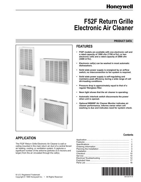
<strong>F52F</strong> <strong>Return</strong> <strong>Grille</strong><strong>Electronic</strong> <strong>Air</strong> <strong>Cleaner</strong>FEATURESPRODUCT DATA• <strong>F52F</strong> models are available with one electronic cell anda rated capacity of 1000 cfm (1700 m 3 /hr), or twoelectronic cells and a rated capacity of 2000 cfm(3400 m 3 /hr).• <strong>Electronic</strong> cell(s) can be washed in most automaticdishwashers.• Solid state power supply is energized by an airflowswitch; no interconnection to fan system is required.• Solid state power supply is self-regulating andmaintains peak efficiency during a wide range of celldirt-loading conditions.• Pressure drop is approximately equal to that of aregular fiberglass filter.• Neon light shows that the air cleaner is operating.• Automatic interlock switch disconnects the powerwhen unit is opened.• Optional W8600F <strong>Air</strong> <strong>Cleaner</strong> Monitor indicates aircleaner performance, informs owner when cellwashing is due and indicates need for system check.APPLICATIONThe <strong>F52F</strong> <strong>Return</strong> <strong>Grille</strong> <strong>Electronic</strong> <strong>Air</strong> <strong>Cleaner</strong> is wall orceiling mounted in the main return air duct of a central forcedair heating, cooling, or ventilation system. It captures asignificant number of the airborne particles (0.5 microns andlarger) from the air circulated through the cell(s).ContentsApplication......................................................................... 1Features ............................................................................ 1Specifications .................................................................... 2Ordering Information ......................................................... 2Planning the Installation .................................................... 4Installation ......................................................................... 6Checkout ........................................................................... 10Service .............................................................................. 10Electrical Troubleshooting ................................................. 12Exploded View................................................................... 17Parts List ........................................................................... 18® U.S. Registered TrademarkCopyright © 1998 Honeywell Inc. • All Rights ReservedX-XX UL<strong>68</strong>-<strong>0074</strong>-9
<strong>F52F</strong> RETURN GRILLE ELECTRONIC AIR CLEANERSPECIFICATIONSIMPORTANTThe specifications given in this publication do notinclude normal manufacturing tolerances. Therefore,this unit may not exactly match the listedspecifications. Also, this product is tested andcalibrated under closely controlled conditions, andsome minor differences in performance can beexpected if those conditions are changed.Models:<strong>F52F</strong> <strong>Return</strong> <strong>Grille</strong> <strong>Electronic</strong> <strong>Air</strong> <strong>Cleaner</strong> (one-cell modelfor up to 1000 cfm [1700 m 3 /hr]). Includes solid statepower supply with air cleaner monitor capability, oneelectronic cell, prefilter, door/grille and airflow switch.<strong>F52F</strong> <strong>Return</strong> <strong>Grille</strong> <strong>Electronic</strong> <strong>Air</strong> <strong>Cleaner</strong> (two-cell modelfor up to 2000 cfm [3400 m 3 /hr]). Includes solid statepower supply with air cleaner monitor capability, twoelectronic cells, prefilter, door/grille and airflow switch.Electrical Ratings:No. ofCellsSystemSize (in.)Maximum Current (A)120V,60 HzCapacity, Efficiency, Pressure Drop:See Fig. 1.220/240V,50/60 HzMaximumPower (W)1 20 x 12.5 0.4 0.2 222 20 x 25 0.4 0.2 36Temperature Ratings:Operating Ambient: 40°F to 125°F (4°C to 52°C).Temperature of <strong>Air</strong>flow Through Cell(s): 40°F to 125°F(4°C to 52°C).Maximum Cell Washing Temperature: 220°F (104°C).Storage and Shipping (Entire Unit): minus 40°F toplus 140°F (minus 40°C to plus 60°C).Mounting:Recesses into duct opening on wall or ceiling. On wallinstallation, mount with hinge on bottom or either side (seeReview Installation Requirements section). Not intended forfloor installations.Weight:<strong>F52F</strong> <strong>Electronic</strong> <strong>Air</strong> 1-Cell 2-Cell<strong>Cleaner</strong> lb kg lb kgShipped 39.2 17.8 58.8 26.7Installed 29.4 13.4 45.3 20.6Cell(s)—included inabove weightsDimensions:See Fig. 2 and 3.Door/<strong>Grille</strong> Type:Egg crate.Cell Size:12-1/2 x 20 in. (318 x 508 mm).9.5 4.3 9.5eaUnderwriters Laboratories Inc. Listed:File No. E30954, Guide No. AGGZ.Canadian Standards Association Listed:File No. LR19060-L.Accessories and Replacement Parts:See Fig. 23.4.3eaORDERING INFORMATIONWhen purchasing replacement and modernization products from your TRADELINE® wholesaler or distributor, refer to theTRADELINE® Catalog or price sheets for complete ordering number, or specify:1. Order number. 4. Type of door/grille—louvered or egg crate.2. Voltage and frequency. 5. Accessories, if desired.3. Dimensions: 20 x 25 or 20 x 12-1/2 in. 6. W8600F <strong>Air</strong> <strong>Cleaner</strong> Monitor, if desired.(508 x 635 or 508 x 318 mm). Specify beige or white color.If you have additional questions, need further information, or would like to comment on our products or services, please write orphone:1. Your local Home and Building Control Sales Office (check white pages of your phone directory).2. Home and Building Control Customer LogisticsHoneywell Inc., 1885 Douglas Drive NorthMinneapolis, Minnesota 55422-4386In Canada—Honeywell Limited/Honeywell Limitée, 155 Gordon Baker Road, North York, Ontario M2H 2C9.International Sales and Service Offices in all principal cities of the world. Manufacturing in Australia, Canada, Finland, France,Germany, Japan, Mexico, Netherlands, Spain, Taiwan, United Kingdom, U.S.A.<strong>68</strong>-<strong>0074</strong>—9 2
<strong>F52F</strong> RETURN GRILLE ELECTRONIC AIR CLEANER1EFFICIENCY, PERCENT1009080706050400(<strong>68</strong>0)500(850)600(1020)700(1190)800(1360)900(1530)3<strong>F52F</strong> ONE CELL CAPACITY IN cfm (m /hr).20 (50).15 (37).10 (25).05 (13)0 (0)1000(1700).25 (62)PRESSURE DROP IN IN. WC (PA)1EFFICIENCY, PERCENT1009080706050800(1360)1000(1700)1200(2040)1400(2350)1600(2720)1800(3060)3<strong>F52F</strong> TWO CELL CAPACITY IN cfm (m /hr).25 (62).20 (50).15 (37).10 (25).05 (13)0 (0)2000(3400)PRESSURE DROP IN IN. WC (PA)1 EFFICIENCY RATINGS BASED ON NATIONAL BUREAU OF STANDARDS DUST SPOT METHOD USING ATMOSPHERIC DUSTAND AMERICAN SOCIETY OF HEATING, REFRIGERATION, AND AIR-CONDITIONING ENGINEERS STANDARD 52.1-92.M7824Fig. 1. <strong>Air</strong> cleaner efficiency and pressure drop at various airflow rates.1-1/8 (29)12-7/8(327)KNOCKOUT FOR 1/2 INCHCONDUIT CONNECTORON BOTTOM OF F521-3/8 (35)7(178)11/16(18)15-3/4 (400)1-3/16(30)3/4 (19)3-11/16(94)3/16(5)(7)11-3/16(284)28(711)17-7/8(454)26(660)1-1/4(32)1-1/8 (29)KNOCKOUT FOR 1/2 INCHCONDUIT CONNECTORON BACK OF F52M11983Fig. 2. Approximate installation dimensions in in. (mm) of one-cell <strong>F52F</strong> <strong>Electronic</strong> <strong>Air</strong> <strong>Cleaner</strong>.3<strong>68</strong>-<strong>0074</strong>—9
<strong>F52F</strong> RETURN GRILLE ELECTRONIC AIR CLEANER29-1/16 (738)23-1/8(587)17-5/16(440)11-1/2(292)5-5/8(143)3/16 (5)(8)13/16 (21)11/16 (18)31 (787)2-1/2 (64)1-1/2 (38)A7 (178)1-1/4(32)10-3/4(273)3/16(5)(7)4-1/16(103)8-1/16(205)22(559)24(610)13-5/8(346)17-11/16(449)1-1/2(38)3/4 (19)7/8 (22)3/4(19)KNOCKOUT FOR 1/2 INCH CONDUITCONNECTOR ON BACK OF <strong>F52F</strong>ig. 3. Approximate installation dimensions in in. (mm) of two-cell <strong>F52F</strong> <strong>Electronic</strong> <strong>Air</strong> <strong>Cleaner</strong>.3-3/8(86)KNOCKOUT FOR1/2 INCH CONDUITCONNECTOR M11984PLANNING THE INSTALLATIONApplication and ConstructionThe air cleaner should be installed in the occupied spacereturn duct opening leading to a central air handling system.All of the air circulated by the system must pass through theelectronic air cleaner.The front door of the electronic air cleaner is hinged toprovide access to the internal components. See Fig. 4.The air cleaner has one or two electronic cell(s) that must beinstalled with the ionizer section (side with fine wires) facingthe door.The cell(s) is held in place by metal hooks and aquarter-turn latch.A spring contact provides the electrical connection betweenthe solid state power supply and the electronic cell(s). Aninterlock switch interrupts the line voltage to the power supplywhen the door is opened. A rocker-type ON-OFF switchallows the air cleaner to be turned off manually. An indicatorlight that is on shows that the air cleaner is energized and thepower supply is producing high voltage.<strong>68</strong>-<strong>0074</strong>—9 4
<strong>F52F</strong> RETURN GRILLE ELECTRONIC AIR CLEANERMETAL MESHPREFILTERONE-CELL MODELCELL HOOKSTWO-CELL MODELPOWER SUPPLYENCLOSURECELL LATCHCELL CONTACTPLATEELECTRONIC CELLMETAL MESHPREFILTERELECTRONICCELLCELLLATCHON-OFFSWITCHINTERLOCKSWITCHCELLCONTACTPLATEHINGEHINGEON-OFFSWITCHINTERLOCK SWITCHPOWER SUPPLYENCLOSUREDOORCELL HOOKSDOORM7820AReview Installation RequirementsThe air cleaner is installed in place of the main return grilleso all the air circulated by the system passes through theair cleaner.It can be installed in either a wall or ceiling, but not in thefloor. See Fig. 5 through 7 for typical installations.Fig. 4. Internal components of <strong>F52F</strong> <strong>Electronic</strong> <strong>Air</strong> <strong>Cleaner</strong>.AIR-FLOWUPFLOWFURNACERETURN GRILLEELECTRONIC AIRCLEANERAIR-FLOWM7809Fig. 5. Typical electronic air cleaner applicationon platform-mounted upflow furnace.(Dotted lines show optional ductwork.)M11985Fig. 6. Typical electronic air cleaner installation onan upflow furnace.5<strong>68</strong>-<strong>0074</strong>—9
<strong>F52F</strong> RETURN GRILLE ELECTRONIC AIR CLEANERRETURNGRILLEELECTRONICAIR CLEANERCOUNTER-FLOWFURNACERETURN GRILLEELECTRONICAIR CLEANERAIR-FLOWM7810Fig. 7. Typical electronic air cleaner application on counterflow (downflow) furnace.(Dotted lines show optional ductwork.)In a wall installation, mount the one-cell air cleaner with thedoor hinge on the bottom so the air cleaner fits between thetwo studs 16 in. (407 mm) on center. The two-cell air cleanerfits between two studs 24 in. (610 mm) on center whenmounted with the hinge on either side or between three 16 in.studs, with center stud removed, when mounted with hinge onthe bottom.Do not install either unit with the hinge on the top because thecell(s) will be awkward to remove.Determine Duct Design RequirementsThe return duct should end at, or slightly behind, the finishedwall surface. Do not use a standard register flange, or thedoor may not fit tightly against the wall.TransitionsTransitions are needed when the duct is a different size thanthe air cleaner. Gradual transitions reduce air turbulence andincrease efficiency. The transition should be 20 degrees orabout 4 in. per running ft (100 mm per 300 linear mm) or lesson each side of a transition fitting.INSTALLATIONWhen Installing this Product…1. Read these instructions carefully. Failure to follow themcould damage the product or cause a hazardouscondition.2. Check the ratings given in the instructions and on theproduct to make sure the product is suitable for yourapplication.3. Installer must be a trained, experienced servicetechnician.4. After installation is complete, check out productoperation as provided in these instructions.CAUTIONElectric Shock Hazard.Can cause electrical shock or equipment damage.Disconnect power before installing air cleaner.Unpack the <strong>Air</strong> <strong>Cleaner</strong>1. Check that all components are included. The unitconsists of:• Door assembly in separate box.• One metal mesh prefilter.• One or two electronic cell(s).• Literature package.2. Lift out and set aside the door/grille assembly and theprefilter. Turn the cell latch (Fig. 4) toward the aircleaner cabinet and remove the electronic cell(s), liftingfrom the side nearest the latch. Set aside.3. Remove the four screws holding the wiringcompartment cover.4. Remove the air cleaner cabinet from the carton.Make Wall Opening1. Size the wall opening to fit the air cleaner as closely aspossible with the air cleaner door hinge on either sideor bottom for the two-cell model, and on the bottom forthe one-cell model. See Table 1 for dimensions.Table 1. Installation Dimensions.Wall Stud Spacing Unit DimensionsModel in. mm in. mm1-cell 16 406 12-7/8 x25-15/16327 x 6592-cell 24 or 32 610 or 813 29-1/16 x 22 738 x 559<strong>68</strong>-<strong>0074</strong>—9 6
<strong>F52F</strong> RETURN GRILLE ELECTRONIC AIR CLEANERONE-CELL MODELSECURE AIR CLEANER TO DUCT OPENINGWITH SCREWS (AT ARROWS).TWO-CELL MODELSECURE AIR CLEANER TO DUCT OPENINGWITH SCREWS (AT ARROWS).M7821AFig. 8. Fasten air cleaner to duct with sheetmetal screws.2. Frame the opening to provide adequate support for theair cleaner. The air cleaner must fit snugly in theopening; allow no more than 1/4 in. (6 mm) from theopening to each side of the cabinet.3. Cover the framing and any unused portion of the wallopening with wallboard, plywood, or other material andfinish to match the wall.Mount <strong>Air</strong> <strong>Cleaner</strong>1. Fit the air cleaner enclosure into the prepared ductopening so the flange on the air cleaner fits tightlyagainst the finished wall surface. The posts on theflange should be on the side desired for the door hinge.2. Tack the enclosure to the wall.3. Fasten the air cleaner enclosure to the wall frame usingsheet metal screws. See Fig. 8. Overtightening thescrews can distort the enclosure and make it difficult tosecure the door with the door latches.WiringCAUTIONElectric Shock Hazard.Can cause personal injury.• The line voltage power source must match thevoltage and frequency of the <strong>F52F</strong>.• The air cleaner must be permanently connected tothe power source. Do not use an extension cord.1. Disconnect power before beginning wiring to avoidelectrical shock or equipment damage. All wiring mustcomply with applicable codes and ordinances. See Fig. 9.2. Connect the white lead from the air cleaner to theneutral side of the 120V supply. Use the solderlessconnector supplied.3. Connect the black lead from the air cleaner to the lineside of the 120V supply. Use the solderless connectorsupplied.4. Connect the air cleaner ground terminal to ground.L1(HOT)1 L2GREENWIRINGCOMPARTMENTWHITEBLACKRETURN GRILLEELECTRONICAIR CLEANER1 120V, 60 HZ POWER SUPPLY. PROVIDE DISCONNECT MEANSAND OVERLOAD PROTECTION AS REQUIRED.M7808Fig. 9. Typical connections for air cleaner.The solid state airflow switch turns the air cleaner on and offin response to airflow; the air cleaner need not be connectedto the system fan.NOTE:If power to the F52 is switched by another means,the airflow switch may be disabled by cutting theairflow switch disable jumper. See Fig. 20.7<strong>68</strong>-<strong>0074</strong>—9
<strong>F52F</strong> RETURN GRILLE ELECTRONIC AIR CLEANERInstall Optional W8600F <strong>Air</strong> <strong>Cleaner</strong> MonitorIf the W8600F <strong>Air</strong> <strong>Cleaner</strong> Monitor is part of the installation,install the W8600F in the desired location and run 3-wirethermostat wiring (up to 18 gauge), independent of any othercurrent-carrying wires, to the air cleaner power compartmentas follows.W8600F LocationThe styling of the W8600F is designed to blend with theT8600 Thermostat family. A special mounting template isincluded in the bag assembly for mounting next to the T8600.The W8600F monitor can, however, be mounted at any otherconvenient location in the living area, or it can be mounted inthe furnace room. It shares no electrical connections with thethermostat.Make certain the location makes it convenient for the user toobserve the display of the device.Mounting W8600FThe following mounting instructions assume that the W8600Fis mounted next to a T8600 Thermostat. If installing themonitor at another location, modify the procedure to fit theinstallation.1. Hold the mounting template (included in the bagassembly) next to the T8600 as shown in Fig. 10.2. Mark the holes for the screw anchors and the3-conductor thermostat cable.3. Remove the template and drill the holes.4. Remove the W8600F from the base.THERMOSTATWALLPLATEMOUNTINGTEMPLATETable 2. Wash Frequency Options.DIP Switch SettingsF1 F2 F3 Wash Frequency (Days)Off Off Off 10Off Off On 20Off On Off 30Off On On 40On Off Off 50On Off On 70On On Off 100On On On 180BACK OF W8600FBATTERYIN HOLDERDIP SWITCHESWIRINGTERMINALS (3)134MOUNTING HOLES (2)WIRING HOLEM11971Fig. 10. Positioning mounting template.5. Position the W8600F base over the holes and install theanchors and screws. Tighten the screws until the baseis mounted firmly on the wall.Select Wash FrequencyUse the W8600F DIP switches to program the time betweenSERVICE indications. Be sure to select the setting accordingto the conditions of the home. Factors to consider include theduty cycle of the EAC, the number of people and pets, andactivities such as woodworking and other crafts that are beingdone in the home.Refer to Table 2 to select the wash frequency. Set theW8600F DIP switches to match the selection. See Fig. 11.The time listed represents actual run time of the EAC, notcalendar days.Fig. 11. Back of W8600F.M11969Wiring1. Run a 3-conductor thermostat cable (up to18 gauge) from the W8600F to the terminal strip on theback of the F52 wiring compartment.IMPORTANTConnect cable to W8600F before attaching to the aircleaner terminals to minimize the risk of damagedue to static electricity.2. Connect the wires to terminals 1, 3 and 4 on theW8600F. See Fig. 11.3. Check that the battery is correctly installed in theW8600F battery holder.4. Snap the W8600F onto the base.5. Turn off the power for the EAC.6. Connect the three wires from the W8600F to the EACterminals 1, 3 and 4. See Fig. 12.<strong>68</strong>-<strong>0074</strong>—9 8
<strong>F52F</strong> RETURN GRILLE ELECTRONIC AIR CLEANERELECTRONIC AIR CLEANERTERMINAL STRIPON POWER BOXW8600F1134Install <strong>Electronic</strong> Cell(s), Prefilter andDoor/<strong>Grille</strong>1. Hold the cell(s) by the handle(s) and fit the end of thecell(s) behind the metal hooks. See Fig. 15.2. Swing the cell(s) into the frame and turn the cell latchesto lock the cell(s) in place. See Fig. 16.INSTALL HANDLE ON END OF CELLCLOSEST TO ACCESS DOOR.GREEN1234BRYGREDBLUETHREE-WIRETHERMOSTAT CABLE1 CONNECT TO W8600F TERMINALS BEFORE CONNECTING TOPOWER BOX.M11974Fig. 12. Wiring W8600F to <strong>Electronic</strong> <strong>Air</strong> <strong>Cleaner</strong> powerbox terminal strip (two-cell model).NOTE: Connect terminal 1 to 1, 3 to 3 and 4 to 4.7. Turn on the EAC power.8. Turn on the system fan.9. Push the W8600F reset button. All four indicators on thedisplay will flash 5 times. The ON indicator will stayactive as long as the EAC is on. See Fig. 13.ROTATE 90DEGREESFOLD TABTO LOCKHANDLEIN PLACEM6047AFig. 14. Attach cell handle to end of cell.3. Reinstall the prefilter by seating it into the rail. Rotate itinto the air cleaner, and seat it on the opposite side.4. Assemble the door/grille to the cabinet as follows:a. Align the door/grille with the frame. Fit the holes inthe door hinge over the mounting posts on the frame.b. Start the hex nuts provided on the posts and tighten.c. Close the door/grille and turn the thumb screws.d. If alignment requires adjustment, loosen nuts, alignand retighten.OnBatteryServiceFault<strong>Air</strong> <strong>Cleaner</strong> MonitorIMPORTANTFor proper air cleaner operation, make sure:• The contacts on the cell(s) meet the springcontacts on the frame.• The arrow on the side of the cell points in thedirection of airflow (toward the wall or ceiling).• The ionizer wires face toward the door/grille.ELECTRONICCELLCELL CONTACTPLATESCELL HOOKSCELL LATCHFig. 13. Complete T8600/W8600F Installation.M15586Attach Cell Handle(s)The plastic handle(s) taped to the packing material must bemounted on the electronic cell(s). The handle(s) can bemounted on either end; choose the end most convenient forinserting and removing the cell(s).1. Hold the handle sideways and insert the solid tab onthe back of the handle into the rectangular slot in thecell. Turn the handle 90 degrees clockwise to align thedivided tab with the square hole. See Fig. 14.2. Insert the divided tab into the square hole.3. Fold up the tab and insert it into the slot to lock thehandle in place. If necessary, press with a bluntinstrument such as the end of a pliers.M9677AFig. 15. Make sure hooks snap over edge of cell.9<strong>68</strong>-<strong>0074</strong>—9
<strong>F52F</strong> RETURN GRILLE ELECTRONIC AIR CLEANERCELL LATCHDOOR LATCHRECEIVER (2)come on, refer to Electrical Troubleshooting section. If aW8600F is part of the installation, also check the wall panel,and make sure the ON indicator is active. When the fan isstopped, the indicator should go off.SERVICECAUTIONSharp Edges.Can cause personal injury.Handle the cell(s) carefully to avoid cuts from thesharp metal edges.Fig. 16. Turn cell latch to lock in place.Painting <strong>Air</strong> <strong>Cleaner</strong>The air cleaner door/grille is painted white and needs noadditional finishing. If another color is desired, remove thedoor/grille from the air cleaner and make sure it is cleanbefore painting.Replacing Door/<strong>Grille</strong>The louvered and egg crate door/grilles are interchangeableon the <strong>F52F</strong> (see Parts List on page 18 for part numbers). Tochange from a louvered to an egg crate door/grille, turn thequarter-turn fasteners to the open position. Open the door/grille and remove the two hex nuts that fasten the door/grilleto the air cleaner cabinet. Install the two tinnerman clips thatare supplied with the egg crate door/grille on the door latchreceivers (Fig. 16). Mount the new door/grille on the aircleaner cabinet with the two hex nuts previously removed.Close the door/grille and turn the thumb screws to engage themating screws in the tinnerman clips.CHECKOUTM9676AInspect the Installation Before Putting<strong>Electronic</strong> <strong>Air</strong> <strong>Cleaner</strong> into OperationMake sure:• The wiring connections in the power box are properlymade with the proper connectors.• The metal mesh prefilter is positioned properly.• The airflow arrows on the cell(s) point away from thedoor/grille.• The electronic cell(s), prefilter and door/grille are cleanand dry.• The contact is good between electronic cell and the powersupply contacts.• The W8600F (if used) wiring connections areproperly made.Check <strong>Air</strong> <strong>Cleaner</strong> OperationWith all components in place, turn on the air cleaner switchand close the door/grille. Energize the system fan and checkthat the neon light, visible through the air cleaner door/grille,lights. This indicates that the air cleaner is energized and thepower supply is producing high voltage. If the light does notCleaning the <strong>Electronic</strong> Cell(s) and PrefilterClean the electronic cell(s) and prefilter regularly every one tosix months. Variables such as number of occupants, activitiesand smoking determine how often cleaning is required. Usethe wash reminder schedule in the literature packet to helpestablish and maintain a regular cleaning schedule.If the air cleaner has the optional W8600F <strong>Air</strong> <strong>Cleaner</strong>Monitor, the SERVICE is activated to indicate that a cell andprefilter washing is due. The SERVICE indicator does notcome on when the prefilter gets clogged; clean the prefilterevery time the cell(s) are cleaned.The cell(s) can be washed in most automatic dishwashers, bysoaking in a tub or at a do-it-yourself coin operated car wash.The prefilter can be vacuumed, brushed, sprayed with agarden hose. Do not wash the prefilter in the dishwasher orcar wash.The heating or air conditioning system can be run while thecell(s) is being washed. Simply turn off the air cleaner switch.Automatic DishwasherCAUTIONBurn Hazard.Can cause personal injury.Allow the cell(s) to cool in the dishwasher at the endof the wash cycle or wear protective gloves to avoidburns. Hot water can accumulate in the tubes thatsupport the collector plates. Tip the cell(s) so thesetubes can drain.IMPORTANT• Check your dishwasher owner manual. Somemanufacturers do not recommend washingelectronic cells in their dishwashers.• If the dishwasher has upper and lower arms,position the cell(s) carefully to allow good watercirculation.• Use care to avoid damaging or bending the cellplates when placing them in the dishwasher. Ifbent, arcing will result.• Very dirty cells, especially from tobacco orcooking smoke, can discolor the plastic parts andlining of the dishwasher. The discoloration is notharmful. To minimize it, wash the cells morefrequently or try a different brand of detergent.• DO NOT ALLOW THE DISHWASHER TO RUNTHROUGH THE DRY CYCLE. This will bake onany contaminants not removed during the washcycle and reduce air cleaner efficiency.<strong>68</strong>-<strong>0074</strong>—9 10
<strong>F52F</strong> RETURN GRILLE ELECTRONIC AIR CLEANER1. Put the cell(s) on the lower rack of the dishwasher withthe airflow arrow pointing up. It may be necessary toremove the upper rack. Do not block water flow to theupper arm, if provided on the dishwasher.HINT:Lay a few large water glasses between thespikes on the lower rack, and rest the cells onthem so the spikes do not damage thealuminum collector blades.2. Using the detergent that works best for normaldishwashing, allow the dishwasher to run through thecomplete wash and rinse cycle. Do not use the drycycle. To avoid burns, let the cell(s) cool completelybefore removing, or wear protective gloves whenremoving the cell(s). Remember that water may betrapped in the tubes that support the collector plates.Tip the cell(s) so these tubes can drain.3. Wipe the ionizer wires and contact board on the end ofthe cell with a clean cloth.4. Inspect the dishwasher. You can rerun the wash and/orrinse cycle with the dishwasher empty if you see dirt orresidue from washing the cell(s). If dirt or residueseems excessive, wash the cell(s) more often or try adifferent detergent.5. Inspect the cell(s) for bent plates; bend back to normalto prevent arcing.SoakingCAUTIONHazardous Chemical.Can cause personal injury.Do not splash the detergent solution in eyes. Wearrubber gloves to avoid prolonged detergent contactwith skin. Keep detergent and solution out of reach ofchildren.NOTE:Always wash the cell(s) first, then the prefilter, tokeep heavy lint from getting caught in the cell(s).1. Use a container that is large enough, such as a laundrytub or trash container, to hold one or both cells. Sharpcorners on the cell(s) can scratch the surfaces.2. Dissolve about 3/4 cup of automatic dishwashingdetergent per cell in enough hot water to cover thecell(s). If the detergent does not dissolve readily, orforms a scum on the water, try another brand or usesoftened water.3. After the detergent has completely dissolved, place thecell(s) in the container to soak for 15 to 20 minutes.Agitate up and down a few times, and then remove.4. Next, wash the prefilter the same way. Empty and rinsethe wash container.5. Rinse the cell(s) and prefilter with a hard spray of veryhot water; rinse the tub clean, then fill the tub with cleanhot water and soak for 5 to 15 minutes. Rinse untilwater draining from the cell(s) and prefilter no longerfeels slippery.6. Wipe the ionizer wires and contact board on the end ofthe cell with a clean cloth.Car WashUse the hand sprayer at a coin-operated car wash to washthe cell(s). Hold the nozzle at least 2 ft (0.6m) away from theunit to avoid damage from the high pressure stream of water.Follow the same sequence of wash and rinse as recommendedfor cars. However, do not wax the cell(s). Rinse untilthe water draining from the cell(s) no longer feels slippery.Reinstalling Cell(s) and Prefilter1. Inspect the cell(s) for broken ionizer wires and bentcollector plates. Repair as necessary.2. Replace the cell(s) properly. The electrical contactboard must face the power supply contacts. The airflowarrows on the cell(s) must point into the air duct. Securewith the latch.3. Reinstall the prefilter. Turn on the air cleaner.4. Close the door/grille and fasten it with the two doorlatches.5. Turn on the system fan. If the cell(s) and prefilter arewet, you may hear arcing (snapping). If the arcing isannoying, simply turn off the air cleaner for two to threehours, or until cells are dry.Cleaning the Door/<strong>Grille</strong>The door/grille may require washing periodically, though notas frequently as the electronic cell(s) and prefilter. When itappears dirty, it can be vacuumed using the brush attachmenton your vacuum cleaner, or disassembled and cleaned byagitating in a solution of mild detergent in warm water.Replacing Ionizer WireBroken or bent ionizer wires can cause a short to ground,often resulting in visible arcing or sparking. On air cleanerswith a W8600F, any short in the ionizer or collector sectionactivates the FAULT indicator on the W8600F wall panel. Donot use the cell until the pieces of broken wire are removed. Itcan be used temporarily with one wire missing, but replacethe wire as soon as possible. See Parts List section for ordernumber.Replacement wires are cut to length with eyelets on bothends for easy installation. To install:1. Hook the eyelet on one end of the wire over the springconnector on one end of the cell. See Fig. 17. Becareful to avoid damaging the spring connector or otherparts of the cell.2. Hold the opposite eyelet with a needlenose pliers andstretch the wire the length of the cell. Depress theopposite spring connector and hook the eyelet over it.11<strong>68</strong>-<strong>0074</strong>—9
<strong>F52F</strong> RETURN GRILLE ELECTRONIC AIR CLEANERREPLACING AN IONIZER WIRE.Tools and EquipmentTroubleshooting the electronic air cleaner requires only acouple of tools:• Needlenose pliers (for stringing ionizer wires).• Ohmmeter with 25 kVdc probe (Fluke model 80K -40 H.V.or equivalent). See Fig. 21.Troubleshooting ProcedurePRESSDOWNSPRINGCONNECTORSCAUTIONElectric Shock Hazard.Can cause personal injury.The <strong>Electronic</strong> <strong>Air</strong> <strong>Cleaner</strong> troubleshooting procedures,Fig. 18 and 19, show how to quickly isolate a problem in theair cleaner. Although a meter is needed for some steps, theprimary diagnostic tools are the neon light and the FAULTindicator (on air cleaners with W8600F).The solid state power supply assembly provided in this aircleaner has no field-serviceable components. Iftroubleshooting indicates a power supply assembly problem,replace the entire power supply assembly. See Parts Listsection for order number.1IONIZERWIREEYELETS1NEEDLENOSEPLIERSTWO EYELETS HOLD IONIZER WIRE TO CELL.IONIZERWIREM1540BFig. 17. Install new ionizer wire by hooking eyelets overspring connectors.Neon LightThe neon light is visible through the door. It is powered by thehigh voltage portion of the power supply. When on, it indicatesthat the air cleaner is powered, the power supply is workingproperly and air is flowing in the system. The neon light willnot be on if air is not flowing through the air cleaner.FAULT Indicator (<strong>Air</strong> <strong>Cleaner</strong>s with W8600F)The FAULT indicator is on the W8600F. It activates to indicateany of the following problems: excessive dirt loading, partialshorting of the collector, continuous ionizer or collector arcing,power supply failure, excessive ionizer current, or anycondition causing a major reduction in high voltage.ELECTRICAL TROUBLESHOOTINGWARNINGElectric Shock Hazard.Can cause personal injury orequipment damage.The following procedures expose hazardous live parts.Disconnect power supply between checks andproceed carefully.IMPORTANTThe following instructions are for use by qualifiedpersonnel only.<strong>68</strong>-<strong>0074</strong>—9 12
<strong>F52F</strong> RETURN GRILLE ELECTRONIC AIR CLEANERMAKE SURE ELECTRONICCELLS ARE CLEAN, DRYAND PROPERLY INSTALLED.MAKE SURE PREFILTER ISCLEAN, DRY ANDPROPERLY INSTALLED.TURN ON ELECTRONIC AIRCLEANER AND SYSTEM FAN.CHECK NEON LIGHT.ONAIR CLEANER IS OK.OFFCHECK CELLS FOR:– BENT COLLECTOR PLATES– BROKEN IONIZER WIRES– DIRT ON INSULATORS– DAMAGED IONIZER ORCOLLECTOR CONTACTTABSYESREPAIR ORREPLACECELLSNOWITH OHMMETER, CHECKFOR SHORT BETWEEN:– CELL FRAME AND IONIZERTERMINAL BOARD– CELL FRAME ANDCOLLECTOR TERMINALBOARDCELLSHORTEDINFINITERESISTANCEWARNING!THIS STEP EXPOSESDANGEROUSLY HIGH VOLTAGE.ONLY A QUALIFIED SERVICETECHNICIAN SHOULDATTEMPT THIS STEP.REMOVE POWER SUPPLYENCLOSURE, ACTIVATEINTERLOCK SWITCH.CHECK FOR CORRECT INPUTVOLTAGE ACROSS:120V MODELS: P1 AND P2TERMINALS ON POWERSUPPLY.220/240V MODELS:QUICK CONNECT TERMINALSON POWER SUPPLYTRANSFORMER.NOFIXWIRINGSHORT AIRFLOW SWITCH DISABLEJUMPER TO GROUND. POWERSUPPLY FUNCTIONS NORMALLY.YESYESNO1REPLACE CELL.ELECTRONIC COMPONENTS ON POWER SUPPLYBOARD ARE NOT FIELD REPLACEABLE.CELL OK.REPLACE AIR-FLOW SWITCHREPLACEPOWERSUPPLY 1M7815BFig. 18. Electrical troubleshooting procedure for <strong>F52F</strong> <strong>Electronic</strong> <strong>Air</strong> <strong>Cleaner</strong>s without a W8600F.13<strong>68</strong>-<strong>0074</strong>—9
<strong>F52F</strong> RETURN GRILLE ELECTRONIC AIR CLEANERSTARTMAKE SURE ELECTRONICCELL(S) ARE CLEAN, DRYAND PROPERLY INSTALLED.MAKE SURE PREFILTER(S)ARE IN CABINET SLOTFARTHEST FROM FURNACE.TURN ON ELECTRONIC AIRCLEANER AND SYSTEMFAN.TO USE THIS CHART:1. FOLLOW THE STEPS IN ORDER; DO NOT SKIP AROUND.2. EACH TIME YOU ISOLATE AND FIX A PROBLEM, GO BACK TO START.3. REPEAT ALL THE STEPS UNTIL THE AIR CLEANER CHECKS OUT OK.WARNINGRISK OF ELECTRIC SHOCKTHESE SERVICING INSTRUCTIONS ARE FOR USE BY QUALIFIED PERSONNELONLY. TO REDUCE RISK OF ELECTRIC SHOCK, DO NOT PERFORM ANYSERVICING OTHER THAN CONTAINED IN THE OPERATING INSTRUCTIONSUNLESS YOU ARE QUALIFIED TO DO SO.CHECK NEON LIGHT.ONOFFPUSH TEST BUTTONAND LISTEN FORSNAPPING SOUND.NOYESREPLACE LIGHT ASSEMBLY.CORRECTWIRING.WIRINGNOT OKCHECK WIRING BETWEENW8600F AND AIR CLEANER.USE MAX NO. 18 3-WIRETHERMOSTAT CABLECONNECTED 1(G) TO 1(G),3(R) TO 3(R), AND 4(B)TO 4(B).WIRING OKCHECK W8600F BATTERYLESS THAN3 VdcREPLACE W8600FBATTERYTYPE BR2082CHECK W8600F PERINSTRUCTIONS PACKEDWITH UNIT. OK?NOREPLACE W8600FOFFOFF3 VdcOR MOREYESPUSH TEST BUTTON ANDLISTEN FOR SNAPPINGSOUND.YESCHECK ON INDICATORON W8600FONDEPRESS AND HOLD DOWNTEST BUTTON. FAULTINDICATOR ON W8600F2SHOULD COME ONONELECTRONIC AIR CLEANERAND W8600F ARE OK.2NOTURN OFF AIR CLEANERAND REMOVE CELL(S)ONLY (NOT PREFILTERS).CLOSE ACCESS DOORAND TURN ONAIR CLEANER.CHECK NEON LIGHT.ONINSPECT CELL(S) FOR:• BENT COLLECTORPLATES• BROKEN IONIZERWIRES• DIRT ON INSULATORS• DAMAGED IONIZEROR COLLECTORCONTACT TABSYESREPAIR ORREPLACECELL(S).NOWITH OHMMETER,CHECK FOR SHORTBETWEEN:• CELL FRAME ANDIONIZER SECTION• CELL FRAME ANDCOLLECTOR SECTIONOFFWARNINGTHIS STEP EXPOSESDANGEROUSLY HIGHVOLTAGE. ONLY AQUALIFIED SERVICETECHNICIAN SHOULDATTEMPT THIS STEP.REMOVE POWER BOX COVER.CHECK FOR CORRECT INPUTVOLTAGE ACROSS:120V MODELS: P1 AND P2TERMINALS ON POWERSUPPLY.220/240V MODELS:QUICK CONNECT TERMINALSON POWER SUPPLYTRANSFORMER.NOFIXWIRING.YESSHORT AIRFLOW SWITCHDISABLE JUMPER TO GROUND.POWER SUPPLY FUNCTIONSNORMALLY.1 FOR POWER SUPPLY REPLACEMENT, SEE FORM 69-1136.2W8600F HAS A LCD DISPLAY WITH FOUR INDICATORS: ON,BATTERY, SERVICE, FAULT.CELLSHORTEDREPLACECELL.INFINITERESISTANCEYESREPLACEAIRFLOWSWITCH.NOREPLACEPOWERSUPPLY.13W8600F OPERATION CAN BE CHECKED SEPARATELY.SEE W8600F INSTRUCTIONS.CELL OK.M11979Fig. 19. Electrical troubleshooting procedure for <strong>F52F</strong> <strong>Electronic</strong> <strong>Air</strong> <strong>Cleaner</strong>s with a W8600F.<strong>68</strong>-<strong>0074</strong>—9 14
<strong>F52F</strong> RETURN GRILLE ELECTRONIC AIR CLEANERBLACK COLLECTOR5BLACKBLACKP3RED IONIZERREDBLACKTESTBUTTONCONTACTBOARDP4J4POWERSUPPLY2J54J1J3P2P1BROWNB4R3Y2G1BLUEREDGREEN1 INTERLOCK SWITCH.42 SHORTING BAR.653 AIRFLOW SWITCH DISABLE JUMPER.2J2J1ORANGEGRAYVIOLETBLACKBLACKW4 W2 W1 W331BLACKBLACKBLACKWHITEGREEN4 OPTIONAL W8600F AIR CLEANER MONITOR. DRIVERBOARD AND CABLE PROVIDED WITH W8600F.5 NEON LIGHT.AIRFLOW SWITCH BOARDFig. 20. Schematic for <strong>F52F</strong> with W8600F.M11975COLLECTORTERMINALIONIZERTERMINALCOLLECTORTERMINALReducing Ozone OdorCAUTIONElectric Shock Hazard.Can cause personal injury.Always disconnect power before working on powersupply.IMPORTANTOnly a trained service technician should perform thefollowing procedure.The electronic air cleaner generates a small amount of ozonein normal operation. During the first week or two of operation,the amount can be higher because of sharp edges on someof the new high voltage metal parts. Normal use dulls theseedges in a short time.M6155Fig. 21. Use an ohmmeter to check electronic cell(s)for short circuits.The average person can detect the odor of ozone inconcentrations as low as 0.003 to 0.010 parts per million(ppm). The electronic air cleaner contributes 0.005 to0.010 ppm of ozone to the indoor air. The U.S. Food and DrugAdministration, and Health and Welfare Canada recommendthat indoor ozone concentration should not exceed 0.050ppm. As a comparison, the outdoor ozone level in major citiesis sometimes as high as 0.100 ppm.15<strong>68</strong>-<strong>0074</strong>—9
<strong>F52F</strong> RETURN GRILLE ELECTRONIC AIR CLEANERHowever, if desired, the ozone generated by the air cleanercan be reduced by moving J5 on the power supply. Thisreduces ozone production about 20 to 25 percent andreduces efficiency about 7 to 10 percent, depending on actualairflow delivered by the furnace blower.To Reduce Ozone Odor1. Open the air cleaner door, turn off the power to the aircleaner, and remove the cell(s).2. Remove the power supply enclosure.3. Find J5 and move it. See Fig. 22.4. Replace the power supply enclosure.5. Replace the cell(s), turn on the power, and close the aircleaner door.P3P4J4J1J5J3Fig. 22. Move J5 shorting bar to reduce ozone productionabout 20 to 25 percent.P1P2M10609<strong>68</strong>-<strong>0074</strong>—9 16
<strong>F52F</strong> RETURN GRILLE ELECTRONIC AIR CLEANEREXPLODED VIEWONE-CELL MODEL1256739138141021114TWO-CELL MODEL6107935481132121114M11987Fig. 23. <strong>F52F</strong> part numbers correspond with Parts List.17<strong>68</strong>-<strong>0074</strong>—9
<strong>F52F</strong> RETURN GRILLE ELECTRONIC AIR CLEANERPARTS LISTPart NumberItem 120 Vac Model 220/240 Vac ModelNumber Description 1-Cell 2-Cell 1-Cell 2-Cell1 Prefilter 208536 208537 208536 2085372 Door/<strong>Grille</strong> (Egg Crate) 32001438-004 32001438-005 32001438-004 32001438-0053 <strong>Electronic</strong> Cell FC37A1171 FC37A1171 (2) FC37A1171 FC37A1171 (2)4 <strong>Air</strong> Flow Switch 4074ETH 4074ETH 4074ETH 4074ETH5 Power Supply Enclosure 208541 208542 208541 2085426 Cell Contact Board 4074EHG 4074EHG (2) 4074EHG 4074EHG (2)7 Cabinet Contact Board 190912A 190912A (2) 190912A 190912A (2)8 On/Off Switch 203321 203321 203321 2033219 Interlock Switch 208543 208543 208544 (2) 208544 (2)10 Power Supply 208416AB 208416AA 208416W 208416Y11 Hex Nut for Door Hinge 208545 (2) 208545 (3) 208545 (2) 208545 (3)12 Metal Cell Hook 196123 (2) 196123 (4) 196123 (2) 196123 (4)13 Neon Lamp Assembly 4074ETE 4074ETE 4074ETE 4074ETEParts and Accessories Not IllustratedPart NumberDescription 120 Vac Model 220/240 Vac ModelCell Handle 137266 137266Ionizer Wires (Must be ordered in multiples of 5.) 136434AA (9/cell) 136434AA (9/cell)<strong>Air</strong> <strong>Cleaner</strong> Monitors (beige color) W8600F1006 W8600F1006Premier White® <strong>Air</strong> <strong>Cleaner</strong> Monitor W8600F1014 W8600F1014<strong>68</strong>-<strong>0074</strong>—9 18
<strong>F52F</strong> RETURN GRILLE ELECTRONIC AIR CLEANER19<strong>68</strong>-<strong>0074</strong>—9
<strong>F52F</strong> RETURN GRILLE ELECTRONIC AIR CLEANERHome and Building ControlHoneywell Inc.Honeywell PlazaP.O. Box 524Minneapolis MN 55408-0524Honeywell Latin American Region480 Sawgrass Corporate ParkwaySuite 200Sunrise FL 33325Home and Building ControlHoneywell Limited-Honeywell Limitée155 Gordon Baker RoadNorth York, OntarioM2H 3N7Honeywell Europe S.A.3 Avenue du Bourget1140 BrusselsBelgiumHoneywell Asia Pacific Inc.Room 3213-3225Sun Hung Kai CentreNo. 30 Harbour RoadWanchaiHong KongPrinted in U.S.A. on recycledpaper containing at least 10%<strong>68</strong>-<strong>0074</strong>—9 J.H. Rev. 5-98post-consumer 20 paper fibers.www.honeywell.com


