XAPP238 "LVDS System Data Framing" v1.0 (12/00) - Xilinx
XAPP238 "LVDS System Data Framing" v1.0 (12/00) - Xilinx
XAPP238 "LVDS System Data Framing" v1.0 (12/00) - Xilinx
Create successful ePaper yourself
Turn your PDF publications into a flip-book with our unique Google optimized e-Paper software.
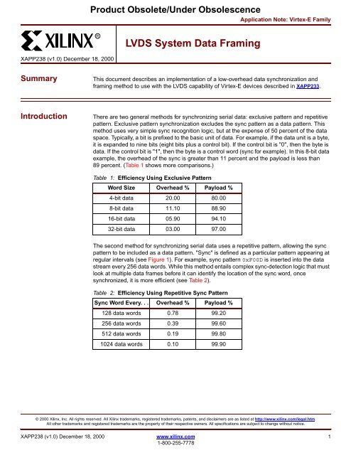
Product Obsolete/Under ObsolescenceApplication Note: Virtex-E FamilyR<strong>LVDS</strong> <strong>System</strong> <strong>Data</strong> Framing<strong>XAPP238</strong> (<strong>v1.0</strong>) December 18, 2<strong>00</strong>0SummaryThis document describes an implementation of a low-overhead data synchronization andframing method to use with the <strong>LVDS</strong> capability of Virtex-E devices described in XAPP233.IntroductionThere are two general methods for synchronizing serial data: exclusive pattern and repetitivepattern. Exclusive pattern synchronization excludes the sync pattern as a data pattern. Thismethod uses very simple sync recognition logic, but at the expense of 50 percent of the dataspace. Typically, a bit is prefixed to the basic unit of data. For example, if the data unit is a byte,it is expanded to nine bits (eight bits plus a control bit). If the control bit is "0", then the byte isdata. If the control bit is "1", then the byte is a control word (sync for example). In this 8-bit dataexample, the overhead of the sync is greater than 11 percent and the payload is less than89 percent. (Table 1 shows more comparisons.)Table 1: Efficiency Using Exclusive PatternWord Size Overhead % Payload %4-bit data 20.<strong>00</strong> 80.<strong>00</strong>8-bit data 11.10 88.9016-bit data 05.90 94.1032-bit data 03.<strong>00</strong> 97.<strong>00</strong>The second method for synchronizing serial data uses a repetitive pattern, allowing the syncpattern to be included as a data pattern. "Sync" is defined as a particular pattern appearing atregular intervals (see Figure 1). For example, sync pattern 0xF<strong>00</strong>D is inserted into the datastream every 256 data words. While this method entails complex sync-detection logic that mustlook at multiple data frames before it can identify the location of the sync word, oncesynchronized, it is more efficient (see Table 2).Table 2: Efficiency Using Repetitive Sync PatternSync Word Every. . . Overhead % Payload %<strong>12</strong>8 data words 0.78 99.20256 data words 0.39 99.605<strong>12</strong> data words 0.19 99.801024 data words 0.10 99.90© 2<strong>00</strong>0 <strong>Xilinx</strong>, Inc. All rights reserved. All <strong>Xilinx</strong> trademarks, registered trademarks, patents, and disclaimers are as listed at http://www.xilinx.com/legal.htm.All other trademarks and registered trademarks are the property of their respective owners. All specifications are subject to change without notice.<strong>XAPP238</strong> (<strong>v1.0</strong>) December 18, 2<strong>00</strong>0 www.xilinx.com 11-8<strong>00</strong>-255-7778
RProduct Obsolete/Under Obsolescence<strong>LVDS</strong> <strong>System</strong> <strong>Data</strong> Framing(y)Bit Pattern (x)<strong>Data</strong>*Bit Pattern (x)<strong>Data</strong>*Fixed amount of time*May contain Bit Pattern (x)Fixed amount of timeX238_01_0915<strong>00</strong>Figure 1: Generic Repetitive Sync PatternFigure 1 shows an example of a repetitive pattern-based sync. With this scheme, the followingtwo parameters must be specified by the designer:1. a sync bit pattern (x), for example 0xF<strong>00</strong>D2. a sync repetition rate (y), for example 257 clocksThe sync pattern x is inserted every y clocks. In a typical repetitive pattern scheme, more than99 percent of the bits transferred are data.In real applications, data frames and garbage frames are differentiated by validated checksumsor some other application-specific characteristic of the data. For this example application, nondataframes are characterized by containing only the filler pattern (0xDEAD and 0xC0DE).The sync bit pattern used in this application is 1111 <strong>00</strong><strong>00</strong> <strong>00</strong><strong>00</strong> 1101 (0xF<strong>00</strong>D) and the syncrepetition rate (frame size) is 256 16-bit words plus sync. Figure 2 shows a typical framebounded by the 16-bit sync words.F<strong>00</strong>D<strong>Data</strong>0<strong>Data</strong>1<strong>Data</strong>2<strong>Data</strong>3<strong>Data</strong>254<strong>Data</strong>255F<strong>00</strong>DX238_02_0509<strong>00</strong>Figure 2: Typical FrameThis application note and accompanying reference designs present a general datasynchronization solution (using the repetitive sync pattern method) and is a companion to the<strong>LVDS</strong> reference design presented in XAPP233. Together, these documents are the basis of acomplete <strong>LVDS</strong> transmitter and receiver design, with data framing and synchronization, for usein a commercial product. These reference designs are based on a 16-bit data word with a 256-word data frame. While the designs are scalable, permitting users to decide on the appropriateword widths, frame sizes, and sync patterns, this document addresses neither customizationnor queue management.2 www.xilinx.com <strong>XAPP238</strong> (<strong>v1.0</strong>) December 18, 2<strong>00</strong>01-8<strong>00</strong>-255-7778
<strong>LVDS</strong> <strong>System</strong> <strong>Data</strong> FramingProduct Obsolete/Under ObsolescenceRGeneral <strong>LVDS</strong>OperationFigure 3 shows the seven major elements of a typical <strong>LVDS</strong>-based system, however, onlyframe alignment (Table 3, element 3) and frame insertion (Table 3, element 5) are covered inthis document and accompanying reference designs. The frame insertion logic contains all thelogic necessary to insert framing information into the user data stream. The frame alignmentlogic is used to realign and frame an <strong>LVDS</strong> data stream.(Typically Many Signals)<strong>LVDS</strong>Receiver(XAPP233)<strong>LVDS</strong>-BasedApplication<strong>LVDS</strong>Transmitter(XAPP233)<strong>LVDS</strong> Bus<strong>LVDS</strong> Bus1 2 3 456 7(Typically aFew Signals)(Typically aFew Signals)Frame Insertion LogicFrame Alignment LogicFigure 3: Typical <strong>LVDS</strong>-Based <strong>System</strong>X238_03_0509<strong>00</strong>Table 3: Description of Typical <strong>LVDS</strong> ElementsElement<strong>LVDS</strong> Bus (incoming)<strong>LVDS</strong> ReceiverFrame Alignment Logic<strong>LVDS</strong>-Based ApplicationFrame Insertion Logic<strong>LVDS</strong> Transmitter<strong>LVDS</strong> Bus (outgoing)DescriptionThe incoming <strong>LVDS</strong> data stream, along with at least oneclock, is carried on one or more controlled impedancetransmission lines. (The clock may be imbedded in thedata.)The <strong>LVDS</strong> receiver (as described in XAPP233) contains lowvoltagedifferential receivers and high-speed serial-toparallellogic. (<strong>LVDS</strong> bus signals are very high speed; the<strong>LVDS</strong> bus is usually fanned out by the receiver to providedata at a manageable speed.)The frame alignment logic is sometimes as simple as a bytealignment circuit; in this application, it contains both wordalignment and payload framing.The <strong>LVDS</strong>-based application can be any function, such assorting, routing, or storing.The frame insertion logic controls the insertion of syncwords and filler data when user data is not available.The <strong>LVDS</strong> transmitter typically contains the high-speed,parallel-to-serial converter and the <strong>LVDS</strong> line drivers, suchas the <strong>LVDS</strong> transmitter described in XAPP233.The outgoing <strong>LVDS</strong> bus must have the same number of dataand clock signals as the target <strong>LVDS</strong> receiver.<strong>XAPP238</strong> (<strong>v1.0</strong>) December 18, 2<strong>00</strong>0 www.xilinx.com 31-8<strong>00</strong>-255-7778
RProduct Obsolete/Under Obsolescence<strong>LVDS</strong> <strong>System</strong> <strong>Data</strong> FramingFrame InsertionThe frame insertion logic simply sends a sync word, followed by a frame of user data or fillerdata, and then repeats. The start and end of data within a stream is identified by headers, tags,or whatever method suits the user’s application. The reference design accompanying thisapplication inserts 0xF<strong>00</strong>D every 256 words. When user data is unavailable, a frame of fillerdata is substituted to maintain the synchronized flow of frames.Figure 4 shows a frame of filler data that is sent in the absence of user data. Sending fillerframes allows the receiving module to maintain (or acquire) lock, even if there is no valid databeing sent.F<strong>00</strong>DDEAD0C0DE1DEAD252C0DE253DEAD254C0DE255F<strong>00</strong>DFigure 4: One Frame with Filler <strong>Data</strong>X238_04_0509<strong>00</strong>The frame insertion logic, Figure 5, is simply a multiplexer controlled by a state machine thatchooses user data or a constant. The state machine chooses what to send based on the usercontrol input.User <strong>Data</strong>16<strong>LVDS</strong>TransmitterConstant16PipelineRegister16 3<strong>LVDS</strong> OutConstantsUser ControlControlState MachineFIFO ControlFigure 5: Frame Insertion Block DiagramX238_05_0509<strong>00</strong>The frame insertion schematic, Figure 6, consists of five major modules, including a controlstate machine (RE_CTL), a constant generator for the sync word (SYNCWORD), and aconstant generator for the filler data (DEADCODE).The pipelined one-hot multiplexer (OHM4_1X16) controlled by RE_CTL sends the user data,the filler data, or a sync word. A sync word is sent followed by 256 words of user data; if the userdata is not present, the multiplexer sends filler data (0xDEAD and 0xC0DE). A final pipelineregister in the outbound data path helps maintain high-speed operation.4 www.xilinx.com <strong>XAPP238</strong> (<strong>v1.0</strong>) December 18, 2<strong>00</strong>01-8<strong>00</strong>-255-7778
<strong>LVDS</strong> <strong>System</strong> <strong>Data</strong> FramingProduct Obsolete/Under ObsolescenceRUSER_DATA[15:0]OHM4_1X16A[15:0]SYNCWORDSYNC[15:0]B[15:0]FD16CESEND_UDRCDEADCODERE_CTLA[15:0]B[15:0]SEND_UDR SEL[3:0]CREREQ[15:0]C[15:0]D[15:0]S[3:0]CD[15:0]CEQ[15:0]C CLRDATAREGFRAMED_DATA[15:0]CCFRAMER_MUXFigure 6: Frame Insertion SchematicX238_06_05090RE_CTL State Machine OperationReferring to the flowchart in Figure 7, the state machine begins in STATE_0 and asserts SEL1,causing the multiplexer to select the sync word as the data to be sent on the next clock.The state of SEND_UD is then checked to determine if there is user data to be sent. If there is,the state machine advances to STATE_3 and asserts SEL0 to select the user data. In this state,FIFO read enable (RE) is also asserted, informing the user that words are being taken. Thesetwo signals remain asserted until the TX_PITCH counter asserts TC, indicating that 256 wordshave been sent and returning the state machine to STATE_0.When in STATE_0, if SEND_UD is false the state machine advances to STATE_1, beginning atwo-state loop that causes the multiplexer to send a word of 0xDEAD followed by a word of0xC0DE. This continues until the TX_PITCH counter asserts its TC, once again returning thestate machine to STATE_0.The TX_PITCH counter determines the frame length. In this example it is 257 clocks: 256clocks for the data and one clock for the sync. This application uses an LFSR (linear feedbackshift register) because of its economy of routing resources and inherent high-speed operation,however, any counter will work. The LFSR has a maximum count of 65,535 and can be scaleddownward to suit the user’s application.<strong>XAPP238</strong> (<strong>v1.0</strong>) December 18, 2<strong>00</strong>0 www.xilinx.com 51-8<strong>00</strong>-255-7778
RProduct Obsolete/Under Obsolescence<strong>LVDS</strong> <strong>System</strong> <strong>Data</strong> FramingCSTATE_0SYNCWORD_F<strong>00</strong>DSEL1SEND_UDRCTX_PITCHTCCSTATE_1DEADCODE_DEADSEL2SEL[3:0]TCCSTATE_2DEADCODE_CODESEL3STATE_3CSEL0TCTCREX238_07_0509<strong>00</strong>Figure 7: RE_CTL State Machine SchematicSending User <strong>Data</strong>To transmit data, the user queues up 256 words of data and then asserts the SEND_UD signal.The RE_CTL state machine responds by asserting the RE signal (user data read enable). Itcontinues sending user data until it has sent 256 words. After sending another sync word(0xF<strong>00</strong>D), the state machine checks the state of SEND_UD again and determines whether tosend another frame of user data or a frame of filler data (0xDEAD and 0xC0DE).FrameAlignmentThe frame alignment logic, Figure 8, detects the user-specified sync word within the datastream, using this pattern to determine the bit offset within the stream to the start of the word.It then steers a barrel shifter to correct for this offset.<strong>LVDS</strong>ReceiverSync Pattern Detector3RX FramerLocked<strong>LVDS</strong> In3 16 301630-BitBarrel ShifterRegisterRX <strong>Data</strong>Figure 8: Frame Alignment Block DiagramX238_08_0509<strong>00</strong>6 www.xilinx.com <strong>XAPP238</strong> (<strong>v1.0</strong>) December 18, 2<strong>00</strong>01-8<strong>00</strong>-255-7778
<strong>LVDS</strong> <strong>System</strong> <strong>Data</strong> FramingProduct Obsolete/Under ObsolescenceRFigure 9 shows the schematic of the frame alignment logic. The frame alignment logicanticipates the subsequent arrival of additional sync words based on the designated syncinterval (256 words in this example) and maintains "locked" status as long as sync wordscontinue to appear in this position. It accomplishes this as follows:1. Words from the <strong>LVDS</strong> receiver cascade through a 30-bit register2. Eight comparators in the SYNC_PAT module simultaneously look for the presence of thesync word on all eight possible bit-pair boundaries3. When the sync word is detected, SYNC_PAT registers the offset and steers a 16-bit barrelshifter (DATBRLSH) to the correct boundary within the 30-bit buffer4. RXFRAMER counts the 256 words following the sync word; then, it checks the followingword again for the presence of the sync pattern5. After three consecutive cycles of successfully detecting sync, the RXFRAMER considersthe receiver to be locked and asserts the LOCKED signalFrom <strong>LVDS</strong>eceiver)CD[15:8]D[7:0]SM238CE_X23330CE_X233CSYNC_PATI[29:0]CESYNC_PATS_POS[2:0]CCE_X233SYNC_PATTERN3 CRXFRAMERCELOCKEDSYNCSYNC_PATCSAV_SPPLOCKEDSYNCSWAP[15:8]BUFX8BUFX8BUFSTAT 5 D[15:0]SWAP[7:0]SWAP[15:0]REG30BITQ[29:0]30-Bit <strong>Data</strong>CE_X2331 of 8 PositionsDATBRLSHSAV_SPPFDI[15:0]CE Q[15:0]S_POS[2:0]I[29:0]CE_X233CCECCX238_09_0509<strong>00</strong>Figure 9: Frame Alignment SchematicFrame Alignment Logic DetailThe frame alignment logic is heavily pipelined to help achieve timing constraints. The incoming16-bit data is sourced from the low-level <strong>LVDS</strong> receiver described in XAPP233. Each module ofthe frame alignment logic is described below:SM238The SM238 module evaluates the BUFSTAT signals coming from the receiver. When BUFSTATindicates that the receiver’s FIFO has data, SM238 asserts CE_X233, causing the framealignment logic to process the buffered words. Processing continues until the BUFSTAT signalsindicate that the FIFO is almost empty, at which time the SM238 module deasserts CE_X233.BUFX8sThe XAPP233 FIFO presents data byte swapped. Two BUFX8 components preceding the 30-bitregister reorder the bytes.REG30BITThe 30-bit register is constructed from two cascaded registers and receives 16-bit input datafrom the receiver. Both registers update on every clock. All 30 bits are continuously available tothe SYNC_PAT and DATBRLSH modules.<strong>XAPP238</strong> (<strong>v1.0</strong>) December 18, 2<strong>00</strong>0 www.xilinx.com 71-8<strong>00</strong>-255-7778
RProduct Obsolete/Under Obsolescence<strong>LVDS</strong> <strong>System</strong> <strong>Data</strong> FramingSYNC_PATThe sync pattern recognition circuit decodes 16 bits of sync pattern. It accomplishesrecognition by way of eight identical comparators, each left-shifted by two bits from one anotherto cover all possible positions of sync in the 30-bit field. Using the bit-mapping suggested inXAPP233, D0 contains all even bits and D1 contains all odd bits. This reduces the number ofpossible skew positions within the stream by ensuring that the word starts on an even-bitboundary. The SYNC_PATTERN signal informs RXFRAMER that a sync pattern has beenfound in the data stream. The position of the sync pattern is sent to the DATBRLSH module asa binary-encoded vector.RXFRAMERRXFRAMER is a one-hot state machine that finds frame sync. In its initial state, the statemachine waits for the SYNC_PATTERN signal, which indicates that the SYNC_PAT module hasdecoded the sync pattern. When the sync pattern is found, the state machine initializes a syncpitch counter (RX_PITCH) and waits for TC. The terminal count normally coincides with thenext sync pattern. If a sync pattern is indeed present, a possible frame boundary is found andthe state machine re-initializes the RX_PITCH counter and waits for a third occurrence of async pattern. If the third pattern is found, the state machine assumes detection of a frame syncand asserts LOCKED. It also asserts SAV_SPP (save sync pattern position), which latches thethree bits of sync pattern position into the barrel shifter.DATBRLSHThis module decodes the 3-bit sync pattern position (from SYNC_PAT) and uses it to select thecorrect alignment of the 16-bit data within the 30-bit field assembled by REG30BIT. The data isthen shifted to the correct position and presented to the user application.RevisionHistoryThe following table shows the revision history for this document.Date Version Revision<strong>12</strong>/18/<strong>00</strong> 1.0 Initial <strong>Xilinx</strong> release.8 www.xilinx.com <strong>XAPP238</strong> (<strong>v1.0</strong>) December 18, 2<strong>00</strong>01-8<strong>00</strong>-255-7778


