Alarm and emergency telephone dialler BA 611
Alarm and emergency telephone dialler BA 611
Alarm and emergency telephone dialler BA 611

You also want an ePaper? Increase the reach of your titles
YUMPU automatically turns print PDFs into web optimized ePapers that Google loves.
Content<strong>Alarm</strong> <strong>and</strong> <strong>emergency</strong> <strong>telephone</strong> <strong>dialler</strong>Operating Instructions <strong>and</strong> Safety Advice<strong>BA</strong> <strong>611</strong>DexaplanT 12IntroductionProper use........................................................................ Page 4Included items ................................................................. Page 4Features <strong>and</strong> equipment .................................................. Page 4Technical information....................................................... Page 5Safety advice..................................................................... Page 5Preparing for first usePlan where you are going to locate the device.................. Page 6Telephone connection....................................................... Page 6Power supply ................................................................... Page 6Making the settings.......................................................... Page 7Positioning the alarm unit................................................. Page 8Operation.......................................................................... Page 9Changing batteries........................................................... Page 11Optional connections........................................................ Page 11Rectifying faults............................................................... Page 12Maintenance <strong>and</strong> cleaningMaintenance of the alarm system..................................... Page 12Cleaning........................................................................... Page 12Disposal.............................................................................. Page 13InformationGuarantee......................................................................... Page 13Service............................................................................. Page 13Declaration of conformity................................................. Page 13IEKOE28_T12_GB.indd 5-218.10.2006 9:41:03 Uhr
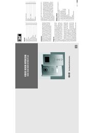
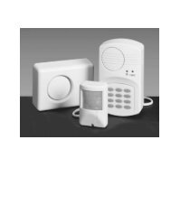
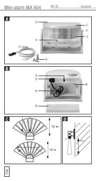
AQ WIUYF: a s dGHL M N27 mmca. 4 mmERTaTBO6 mP100°fC{Ioi22 mm&&}qwertyuDK180°p[]ELHDFGca.40°6 mAKSJmax. 90°IntroductionIntroductionPlease read carefully <strong>and</strong> completely through these operatinginstructions <strong>and</strong> fold out page 3, the page with theillustrations. These operating instructions form part of theproduct <strong>and</strong> contain important information about bringingthe product into use <strong>and</strong> its h<strong>and</strong>ling. Always observe allthe safety advice. If you have any questions or are unsureof how to h<strong>and</strong>le the device please consult our Internetpage at www.dexaplan.com or contact our service centre(see the section about “Service”). Keep these instructions<strong>and</strong> if necessary pass them on to a third party.Proper useThis alarm <strong>and</strong> <strong>emergency</strong> <strong>telephone</strong> <strong>dialler</strong> is intendedexclusively for use in internal rooms in private houses.The power for the alarm unit is provided by the supplied9 V DC mains adapter connected to the 230 V ~ AC, 50 Hzmains supply. A 9 volt block backup battery (not included)ensures the functions are retained if the mains supply isinterrupted. For the dialling function to work connectionto an analogue <strong>telephone</strong> line is required.This alarm <strong>and</strong> <strong>emergency</strong> <strong>telephone</strong> <strong>dialler</strong> can be armed<strong>and</strong> disarmed using the keypad or the remote control.A programmable entry delay <strong>and</strong> an exit delay allow youto arm or disarm the unit from within the monitored area.The motion detector integrated into the alarm unit reactsto the motion of people in the monitored area. On alarmthe alarm unit dials the <strong>telephone</strong> numbers you havepreprogrammed into it. In addition the siren integratedinto the alarm unit can give off an audible alarm sound.The alarm can also be triggered immediately by a panicbutton.Alternatively the unit can be set to give a gong chime ondetection of motion.The manufacturer shall not be liable for damage causedby improper use or incorrect operation.Included itemsSee Fig. AQ 1x <strong>Alarm</strong> unit <strong>BA</strong> <strong>611</strong>W 2x Masking stickersE 2x Screws for alarm unitR 2x Dowels for alarm unitT 1x Remote control <strong>BA</strong> <strong>611</strong> RTa 1x Battery CN23 A, 12 V alkalineY 1x Telephone cable adapter (only included insome countries)U 1x Telephone connection cable (approx. 2 m,with RJ11 plug)I 1x Mains adapter with approx. 1.8 m cable1x Operating instructionsFeatures <strong>and</strong> equipment<strong>Alarm</strong> unit <strong>BA</strong> <strong>611</strong>See Fig. BO Telephone line connection “LINE”P Telephone connection “PHONE”See Fig. C{ Motion detector (PIR)} Power LEDq LED for low battery / detectionw LC displaye Number keys 0 to 9r “PROG” keyt “PAUSE” keyy “OK” keyu “PANIC” keyi keyo keySee Fig. Dp Siren[ Mains adapter connection socket (9 V)] Gong On / Off switchSee Fig. EA Connection compartment coverS Screw for connection compartment coverD Screw holes for mountingF Connection terminalsG Recess slotH Battery compartmentJ Screw for battery compartment coverK Battery compartment coverL Battery connectorRemote control <strong>BA</strong> <strong>611</strong> RSee Fig. F: “PANIC” keya Check LEDs “ ” key for arming deviced “ ” key for disarming deviceSee Fig. Mf Battery compartment coverDisposalDispose of packaging materials, used batteries <strong>and</strong> wornout devices at a local authority approved disposal facility.In accordance with European Directive 2002/96/EC (coveringwaste electrical <strong>and</strong> electronic equipment) <strong>and</strong> itstransposition into national legislation, worn out electricaldevices must be collected separately <strong>and</strong> recycled. Takeout the batteries before you dispose of electrical devices.As the end user you have a duty to recycle or properlydispose of your used batteries. Batteries must not bedisposed of with the household refuse.GB/IE IE IE 13InformationGuaranteeThis product carries a 3-year guarantee from the date ofpurchase. Please retain the sales voucher as proof ofpurchase. In the event of a claim under the guaranteeplease contact the service centre for your country to ensurethat your goods can be returned at no cost. Furthermore,the guarantee is restricted to defects in material<strong>and</strong> manufacture only. It does not cover batteries, wear<strong>and</strong> tear or damage to fragile parts. The product is intendedfor private <strong>and</strong> domestic use exclusively. It is notintended for commercial use. No liability is accepted fordamages in the event of a break-in. An alarm is no substitutefor security protection <strong>and</strong> does replace your obligationto be careful. The guarantee is void in the event ofmisuse or improper h<strong>and</strong>ling, the use of force or attemptedrepairs unless carried out by the service centre. Thisguarantee does not affect your statutory rights.ServiceInformation on what to do in the event of a problem canbe found on the Internet at www.dexaplan.com.In the event of questions please contact our service centreby e-mail (service@dexaplan.de) or <strong>telephone</strong>( T 18 90 / 85 18 51) Monday-Friday, 8:30 - 17:00hours. There you will obtain all the necessary informationabout service procedures such as returning devices etc.Declaration of conformityDexaplan GmbH hereby declares that the alarm <strong>and</strong><strong>emergency</strong> <strong>telephone</strong> <strong>dialler</strong> complies with the basicrequirements <strong>and</strong> the other relevant regulations ofDirective 1999 / 5 / EC. Conformity has been demonstrated.The complete declaration of conformity can be read at:www.dexaplan.comDexaplan GmbHPaul-Böhringer-Str. 3 · 74229 OedheimSt<strong>and</strong> der Informationen 10/2006 · Ident.-No.: 10-2006-<strong>BA</strong> <strong>611</strong>- IEDisposal / InformationKOE28_T12_GB.indd 3-518.10.2006 9:41:10 Uhr
Technical information<strong>Alarm</strong> unit <strong>BA</strong> <strong>611</strong>Operating voltage: 9 V DCCurrent input: 130 mA (alarm), < 5 mA (st<strong>and</strong>by)Power supply: From the supplied mainsadapter or the backup battery(9 volt block 6LR61,not included)Radio receiver: 433.92 MHzSiren:100 dB(A) +/- 5 dB(A) at 0.3 m(mains operation)Siren duration (max.): Approx. 30 sec. / approx. 30 sec.pause / approx. 30 sec. alarmGong function: Can be deactivated; signalseach detected motion with agong soundProgrammable<strong>telephone</strong> numbers: Max. 5 numbersAutomatic dialling: Up to 5 timesProgrammable code: 3 to 6 digitsExit delay:Approx. 55 sec.Entry delay: Programmable: 0 / 5 / 10 / 15 /20 sec.Operating temperature: 0 °C to + 39 °CArea of use:Interior roomsHousing material: ABSHousing dimensions: Approx. 86 x 150 x 46 mm(W x H x D)Weight:Approx. 197 g (without battery,without accessories)Motion detector (attached to the alarm unit)Sensor:Passive infrared (PIR)Detection angle: Approx. 100 ° horizontalDetection range: Approx. 6 m at 20 °C (transversemotion, mounting heightapprox. 0.5 to 2 m)Remote control <strong>BA</strong> <strong>611</strong> ROperating voltage: 12 V DCCurrent input: max. 25 mAPower supply: 1x battery 12 V, alkaline(type CN 23 A)Transmission frequency: 433.92 MHzTransmission range: Approx. 20 m (in open space)Coding:Factory set unique codeFunction indicator: LEDOperating temperature: 0 °C to + 40 °CHousing material: ABSHousing dimensions: Approx. 45 x 67 x 16 mm(W x H x D)Weight:Approx. 34 g (with battery)Mains adapterPower supply: 230 V ~ AC, 50 HzPower consumption: 4.5 VAOutput: 9 V DC, max. 500 mASafety adviceThe following advice is intended for your safety <strong>and</strong> satisfactionduring operation of the device. Please note thatnon-observation of this safety advice can lead to considerabledanger.Explanation of the symbols <strong>and</strong> terms used:c Danger! Non-observance of this instruction oradvice could endanger life <strong>and</strong> health.m Attention! Non-observance of this instruction oradvice will endanger property.Tip! Observance of this instruction or advice willachieve best performance.Introduction / Safety advicec Danger!• Operate the alarm unit with 9 V DC only! Check beforeconnecting the mains adapter to the mains that theelectricity supply circuit is 230 V ~ 50 Hz <strong>and</strong> is fittedwith a max. 16 amp fuse or trip. Do not connect anyother power supply to the connection terminals.Otherwise there is a risk to life <strong>and</strong> limb!• Do not leave small children unattended with thepackaging material, small parts <strong>and</strong> batteries!Otherwise there is a risk to life from suffocation!• Do not leave small children unattended with the device!Otherwise there is a risk to life <strong>and</strong> limb!• Make sure that the alarm sound is not triggered whensomeone is in its direct vicinity Otherwise there is arisk of severe hearing damage!• Wear ear protection when you check the siren.Otherwise there is a risk of severe hearing damage!• Do not damage any cables or pipes for gas, electricity,water or telecoms when you are drilling or mountingthe device! Otherwise there is a risk to life <strong>and</strong> limb!• Do not allow the device to come into contact withmoisture! Otherwise there is a risk to life <strong>and</strong> limb!• H<strong>and</strong>le the mains adapter cable carefully! Place allcables in such a position that they cannot be damagedor become a trip hazard. Otherwise there is arisk to life <strong>and</strong> limb!• Avoid skin or bodily contact with used or damagedbatteries! Wear suitable protective gloves <strong>and</strong> clothing!Otherwise there is a risk of injury from corrosivesubstances!• Do not short-circuit or attempt to recharge the batteries!Otherwise there is a risk to life from explosion!• If the batteries are opened or burned there is a riskof explosion!• Never let children play with batteries. Swallowingbatteries can result in serious damage to health.• Do not place the device near fire, heat, or subject itto prolonged temperatures of over 50 °C! OtherwiseIE KOE28_T12_GB.indd 518.10.2006 9:41:11 Uhr
Preparing for first usePreparing for first usePress the OK key y to confirm.Wait 10 seconds until the device automatically quitsthe settings mode.Switching automatic dialling on / off:You can switch off the automatic dialling function.The device calls all the stored <strong>telephone</strong> numbers if theautomatic dialling function is switched on when analarm is triggered.The LC display shows if the automatic dialling functionis not switched on. Factory setting: “CALL ON” (diallingfunction switched on)Enter the current password.Press the PROG key r a sufficient number of timesuntil the symbol flashes at the top of the LC displayw.Press the OK key y to confirm.Use the key o <strong>and</strong> key i to select “CALLON” (dialling function switched on) or “CALL OFF”(dialling function switched off).Press the OK key y to confirm.Wait 10 seconds until the device automatically quitsthe settings mode.Selecting the number of dialling processes:You can select the number of times the automatic diallingfunction dials the numbers as between once <strong>and</strong> 5times. Every stored <strong>telephone</strong> number will be called thisnumber of times, whether or not the call is answered.Factory setting: 3 timesEnter the current password.Press the PROG key r a sufficient number of timesuntil the word “CYCLE” flashes at the top of the LCdisplay w.Press the OK key y to confirm.Using the key o <strong>and</strong> the key i select thenumber of automatic dialling processes (1 / 2 / 3 / 4 / 5).Wait 10 seconds until the device automatically quitsthe settings mode.Setting the entry delay:Here you can set the time you have, from the time anymotion is detected by the device in the armed state, tocancel the alarm before the siren starts or the <strong>telephone</strong>numbers are automatically dialled.Factory setting: 20 seconds.Enter the current password.Press the PROG key r a sufficient number of timesuntil the word “ENTRY” flashes at the top of the LCdisplay w.Press the OK key y to confirm.Using the key o <strong>and</strong> the key i select thelength of the entry delay (0 / 5 / 10 / 15 / 20 seconds).Press the OK key y to confirm.Wait 10 seconds until the device automatically quitsthe settings mode.Setting the date / time display:1. Enter the current password.2. Press the PROG key r a sufficient number of timesuntil the word “TIME” flashes at the top of the LCdisplay w.3. Press the OK key y to confirm.4. The LCD display now shows:05 – 01 – 01 12 - 00= Year – Month – Day Hours - Minutes5. Select the appropriate field by pressing the OK key ythe required number of times.The selected field flashes.6. Using the key o <strong>and</strong> the key i select thedesired setting.7. Press the OK key y to confirm.8. Repeat items 6 <strong>and</strong> 7 until all the values have beenentered.9. Wait 10 seconds until the device automatically thesettings mode.Reset:If you wish to delete all the settings or you have forgottenyour password, you can initiate a reset as follows:Keep the PROG key r pressed until you hear a pipsound.Now immediately press the Pause key t until youhear a pip sound.Now remove the battery <strong>and</strong> disconnect the mainsadapter. After 2 minutes insert the battery again<strong>and</strong>/or reconnect the mains adapter.Now all the factory settings <strong>and</strong> the factory-installedpassword (“000”) are restored.Positioning the alarm unit1. Limiting the detection range/angle:In the as-supplied condition the motion detector has adetection angle of approx. 100 ° <strong>and</strong> detection range ofapprox. 6 m (at a mounting height of 0.5 - 2 m) (see Fig. G).You can modify the detection range <strong>and</strong> angle by adjustingthe motion detector.To limit the detection angle use one of the two suppliedmasking stickers W (complete or cut to size).See Fig. HLimited horizontal detection angle (approx. 40 °) e.g.as a crossing detector.See Fig. IYou can disable the motion detector by applying thewhole masking sticker, e.g. if detection is to be performedby an externally connected detector (see thesection on “Optional connections”).2. Positioning:You can position the alarm unit upright or lying down.If the surface is very smooth it is recommended that youplace the device lying down.Placing the device lying down (see Fig. K):Turn the motion detector { carefully through 180 °horizontally.Place the alarm unit Q down in the desired location.Carefully turn the motion detector vertically into thedesired direction (max. 90 °).Mounting the device on a wall:Find a suitable place to mount the device on a wall.Before you fix the alarm unit Q permanently intoplace, carry out the steps described in section 3“Checking the functions” at the planned mounting site.If the alarm <strong>and</strong> <strong>emergency</strong> <strong>telephone</strong> <strong>dialler</strong> isfunctioning properly, drill two suitable holes 27 mmapart <strong>and</strong> horizontal (see Fig. L) at the planned location.Use the supplied screws E <strong>and</strong> dowels R to fix thedevice in place. The screw heads must be left projectingapprox. 4 mm (see Fig. L) from the surface ofthe wall.Push the screw holes for mounting the device D onto the screws until the alarm unit is firmly suspendedfrom the wall.3. Checking the functions:Checking that the remote control is functioningproperlyDisarming is confirmed by one pip.The word “ARM” disappears from the LC display wof the alarm unit.Checking the <strong>emergency</strong> alarm:The device has an <strong>emergency</strong> alarm function(Panic function).Press the panic key : on the remote control T.The siren sounds for 30 seconds (if the siren isswitched on – see section “Switching the siren on / off”)<strong>and</strong> the programmed <strong>telephone</strong> numbers are called(if the automatic dialling function is switched on –see section “Switching automatic dialling on / off).After 30 seconds pause the siren sounds for a secondtime for 30 seconds.To stop the alarm <strong>and</strong> the dialling process press thekey d on the remote control.The alarm unit sounds a pip <strong>and</strong> the alarm is nowswitched off.Checking the function of the motion detector:Set the gong on / off switch ] on (setting “I”). Thegong sound sounds once.After approx. 50 seconds delay the gong soundsagain.Now move into the range of detection of the motiondetector {.If the motion detector detects your motion the gongsound sounds 2 x.Set the gong on / off switch ] off (setting “0”).(assuming that the memory location has been assigneda <strong>telephone</strong> number).Wait until the device automatically quits the diallingprocess.OperationIf you entered an incorrect password <strong>and</strong> confirmed itwith the OK key y, the device responds with an “errorsound” <strong>and</strong> automatically returns to the normal mode.Arming the alarm <strong>and</strong> <strong>emergency</strong> <strong>telephone</strong> <strong>dialler</strong>:Arming with the remote controlPress the keyon the alarm unitEnter the current password.Press the OK key y.The alarm unit sounds three pips <strong>and</strong> “ARM” appearsat the bottom of the LC display w.You now have approx. 55 seconds (exit delay) toleave the monitored area without triggering the alarm.After this exit delay has expired the device sounds apip.The alarm <strong>and</strong> <strong>emergency</strong> <strong>telephone</strong> <strong>dialler</strong> is nowarmed.Note: In the armed state the gong function is not activated,even if the gong On / Off switch ] is in setting “I”.The alarm sounds - triggered by the detected motionIn the armed state the motion detector { detects someChecking the automatic dialling function:Press the key on the remote control to arm the Keep the PROG key r pressed until you hear a pip After the set entry delay expires:alarm unit Q.sound.If the alarm is triggered, the word “TRIGGER” appearsArming is confirmed by three pips.Now press a memory location number (number keys at the bottom of the LC display w.The LC display w of the alarm unit shows “ARM”. e “1” to“5”). The dialling unit now automatically The siren p sounds for 30 seconds (if the siren isDisarm the siren unit by pressing the key d on dials the associated assigned <strong>telephone</strong> number <strong>and</strong> switched on). After 30 seconds pause the siren soundsPress the OK key y to confirm.the remote control.the <strong>telephone</strong> number flashes on the LC display w for a second time for 30 seconds. IE IE motion.TheLED q illuminates once briefly.KOE28_T12_GB.indd 8-918.10.2006 9:41:13 Uhr
Preparing for first usePreparing for first useAs determined by the automatic dialling function(factory setting: dialling function switched on) <strong>and</strong>the set number of dialling processes the alarm <strong>and</strong><strong>emergency</strong> <strong>telephone</strong> <strong>dialler</strong> dials all the stored <strong>telephone</strong>numbers in a cycle:1st <strong>telephone</strong> number (30 sec.) - 3 sec. wait -2nd <strong>telephone</strong> number (30 sec.) - 3 sec. wait -3rd <strong>telephone</strong> number (30 sec.) - 3 sec. wait -4th <strong>telephone</strong> number (30 sec.) - 3 sec. wait -5th <strong>telephone</strong> number (30 sec.) - 3 sec. wait -1st <strong>telephone</strong> number (30 sec.) - 3 sec. wait ....etc.If the person called accepts the call, he will hear an alarmsound (even if the siren is switched off ) until the <strong>telephone</strong>connection is automatically stopped after max. 35 secondsby the alarm unit.If the <strong>telephone</strong> connection of the dialling device <strong>and</strong> thecalled <strong>telephone</strong> device have the features to enable thecaller display function to work then the <strong>telephone</strong> numberof the dialling device is displayed on the LC display of thecalled <strong>telephone</strong> device. Even if one or more of the calledpeople accept the calls, all the <strong>telephone</strong> numbers (eventhose who have already answered) are called for the setnumber of dialling processes. The dialling cycle can onlybe interrupted by disarming the device.If the alarm <strong>and</strong> <strong>emergency</strong> <strong>telephone</strong> <strong>dialler</strong> is not disarmedduring or after an alarm then it remains armed.The alarm can be triggered again after the end of the sirensounding process (approx. 90 seconds) or at the endof the dialling cycle.Enter the current password.Press the OK key y.If appropriate, the alarm sound stops.If appropriate, the flashing word “TRIGGER” disappears.The alarm unit sounds a pip.The word “ARM” disappears from the LC display w.The alarm <strong>and</strong> <strong>emergency</strong> <strong>telephone</strong> <strong>dialler</strong> is nowdisarmed.Note: Whilst the alarm unit is dialling a <strong>telephone</strong>number, i.e. it is establishing a <strong>telephone</strong> connection, thealarm <strong>and</strong> <strong>emergency</strong> <strong>telephone</strong> <strong>dialler</strong> cannot be disarmedusing the keys on the device. The remote controlcan be used to disarm the device at any time.Switching the panic alarm On / Off:Press the PANIC key u on the alarm unit or the“PANIC” key : on the remote control.If the alarm is triggered, the word “TRIGGER” appearsat the bottom of the LC display w.The siren p sounds for 30 seconds (if the siren isswitched on – see section “Switching the siren on / off”)<strong>and</strong> the programmed <strong>telephone</strong> numbers are called(if the automatic dialling function is switched on –see section “Switching automatic dialling on / off).After 30 seconds the siren sounds for a secondtime for 30 seconds.To stop the alarm <strong>and</strong> dialling process, enter yourcurrent password <strong>and</strong> press the OK key y or pressthe key d on the remote control.The flashing word “TRIGGER” disappears.The alarm unit sounds a pip <strong>and</strong> the alarm is nowswitched off.Note: Whilst the alarm unit is dialling a <strong>telephone</strong> number,i.e. it is establishing a <strong>telephone</strong> connection, the panicalarm cannot be disarmed using the keys on the device.The remote control can be used to disarm the device atSwitching the gong function on/off:Set the gong On / Off switch ] on (setting “I”).The gong sound sounds once.After approx. 50 seconds delay a pip sounds. Thegong function is now activated.If the motion detector { detects some motion, theLED q illuminates once more <strong>and</strong> the gongsound sounds 2 x.To switch the gong function off again, set the gongOn / Off switch ] off (setting “0”).Note: In the armed state the gong function is not activated.Summary of the last 5 alarm events:This function is not available when in the setting modenor when the alarm <strong>and</strong> <strong>emergency</strong> <strong>telephone</strong> <strong>dialler</strong> isarmed.Press the key i repeatedly.The times of the last 5 alarm events are displayedone after the other.Wait approx. 10 seconds <strong>and</strong> the display mode automaticallyswitches off again.Summary of the stored <strong>telephone</strong> numbers:This function is not available when in the setting modenor when the alarm <strong>and</strong> <strong>emergency</strong> <strong>telephone</strong> <strong>dialler</strong> isarmed.Press the key o repeatedly.The stored <strong>telephone</strong> numbers are displayed oneafter the other.Unassigned memory locations are shown as“- - - - - - - - - - - - - -”.Wait approx. 10 seconds <strong>and</strong> the display mode automaticallyswitches off again.Summary of the soundsDisarming the alarm <strong>and</strong> <strong>emergency</strong> <strong>telephone</strong><strong>dialler</strong>:battery”. In the armed state the alarm unit is suppliedDisarming with the remote controlwith power for approx. 24 hours after the LED q Description of the connections (see Fig. N)Press the key dstarts to illuminate.INPUT: If an external connection between INPUT <strong>and</strong>on the alarm unitany time.is broken a gong sound sounds (if the gong10 IE IE 11SoundThree pipsSiren alarmSingle gongsoundTwo gong soundsChanging batteriesMeaningThe exit delay is activated, thearming of the alarm <strong>and</strong> <strong>emergency</strong><strong>telephone</strong> <strong>dialler</strong> will beactivated after approx 55 seconds.The siren sounds1. Triggered by motion detection– after the set entry delay inthe cycle:30 sec. on – 30 sec.pause – 30 sec. on.2. Triggered by pressing the“PANIC” key u or : as apanic alarm.Gong switch was set to setting“I”, the gong function is still notactivated.Motion was detected,the gong function is activated.<strong>Alarm</strong> unitIf the LED q illuminates once every three seconds(from approx 7.7 V + - 0.5 V), then you should renew the9V block battery. Replace the battery as described insection “Power supply” under “<strong>Alarm</strong> unit - 9 V blockRemote control h<strong>and</strong>setIf the check LED a is weak when the keys on the remotecontrol are operated <strong>and</strong>/or the range of the remote controlis reduced then the battery needs to be replaced (battery12 V, alkaline (type CN 23 A or L1028)).Push the battery compartment cover f downwardsusing light pressure (see Fig. M).Replace the battery with a new one. Insert the newbattery, observing the correct polarity (see markingin the battery compartment).Push the battery compartment cover back on to thehousing again.Check that the remote control is working properly.Optional connectionsIn order to be able to connect optional external devicesyou must first expose the necessary terminal connectionsin the alarm unit:Remove the screw S from the connection compartmentcover with a crossheaded screw driver (seeFig. E).Push the screwdriver into the recess slot G <strong>and</strong>first lift up then take off the connection compartmentcover.Then you can make the desired connections at theconnection terminals F (see “Description of theconnections”). Use cable with a wire cross sectionof 0.2 – 0.3 mm, e.g. <strong>telephone</strong> cable.Guide all the connected cables out of the alarm unitthrough the recess slot G.Put the connection compartment cover A back inplace.Tighten the screw S on the connection compartmentcover again.function is switched on) or an alarm is triggered(in the armed state), however only afterthe end of the exit delay; if at the end of theexit delay this terminal is not connected tono alarm will be triggered.: 0 V (neutral)SIREN *: 12 V (max. 150 mA) when the alarm istriggered (irrespective of whether the internalsiren is switched on or off).NA: No function.Siren *:You can connect an external siren (not included) operatingat 9 or 12 V DC, max. 150 mA to the <strong>and</strong> SIRENterminals.Reed contact:You can connect a reed contact (magnetic contact asopening detector (NC), not included) as a door or windowopening detector to the INPUT <strong>and</strong> terminals. Up to 6reed contacts can be connected in series.Other contacts:The potential-free contacts of other detectors or systemscan be connected to trigger the alarm / dialling function.Opener contacts (NC) can be connected to the INPUT<strong>and</strong> terminals (with more than one contact: connectedin series).* If the power supply from the mains adapter fails thenthere is no voltage at the SIREN terminal. The INPUTterminal remains active during operation from thebackup battery.KOE28_T12_GB.indd 10-1118.10.2006 9:41:14 Uhr
Rectifying faults / Maintenance <strong>and</strong> cleaningRectifying faultsFault Cause RemedyFault Cause RemedyFault Cause RemedyMotion detectordetects motionwithout apparentreason.The range of themotion detectoris not adequate.The LEDflashes regularly.The callednumber doesnot receive acall on alarm.Pets, air movements,directlight, etc.Ambient temperatureis too high(20 °C is optimal).Device is mountedtoo low or toohigh.There is nobackup batteryconnected or theconnected backupbattery is tooweak.The <strong>telephone</strong>number was incorrectlyor notentered.Change theposition of themotion detector.Use a maskingsticker torestrict a particularpart ofthe detectionangle / range.Change theposition of themotion detector.Change themountingheight or theinclination ofthe motiondetector.Connect a newbackup battery.Enter the <strong>telephone</strong>numberagain.The devicedoes not reactto the password.Dialling functionis switched off( appears onthe LC display.The <strong>telephone</strong>line is faulty.You have notyet given acomm<strong>and</strong> afterpassword entry.The passwordentered iswrong.Set the diallingfunction on.( does notappear on theLC display.Check the<strong>telephone</strong> linewith ananalogue <strong>telephone</strong>.Press the OKkey y to arm/disarm thedevice.Press the PROGkey r to entersettings mode.Enter the correctpassword.If you haveforgotten thepassword, setthe device backto the factorysettings as describedin thesection “Changingthe password”.Your settingswere notstored.There are otherfaultsThe settingswere not confirmed.Press the OKkey y toconfirm thesettings.Carry out a reset(see section“Making thesettings” item“Reset”).Should you have further questions or problems pleaseconsult www.dexaplan.com where you can find informationon problem h<strong>and</strong>ling.Maintenance <strong>and</strong> cleaningMaintenance of the alarm systemYou should regularly check the device to see that it issafe <strong>and</strong> working properly.CleaningBefore you clean the device, pull the mains adapter outof the mains socket. Use a dry or slightly moist cloth forcleaning the device. Never immerse the device in water.Do not use solvents to clean the device.12 IEKOE28_T12_GB.indd 1218.10.2006 9:41:15 Uhr