EN40 Electronic Pressure Regulators (Intrinsically Safe) 20113
EN40 Electronic Pressure Regulators (Intrinsically Safe) 20113
EN40 Electronic Pressure Regulators (Intrinsically Safe) 20113

Create successful ePaper yourself
Turn your PDF publications into a flip-book with our unique Google optimized e-Paper software.
DIST. AUTORIZADO®MEX (55) 53 63 23 31QRO (442) 1 95 72 60MTY (81) 83 54 10 18ventas@industrialmagza.comWEB CONTROL PRODUCTSUser ManualElectro-Pneumatic ConverterModel <strong>EN40</strong>-IS(i)FORM NO. L-<strong>20113</strong>-E-0501
DIST. AUTORIZADOIn accordance with Nexen’s established policy of constant product improvement, the specifications contained in thismanual are subject to change without notice. Technical data listed in this manual are based on the latest informationavailable at the time of printing and are also subject to change without notice.®MEX (55) 53 63 23 31QRO (442) 1 95 72 60MTY (81) 83 54 10 18ventas@industrialmagza.comTechnical Support:800-843-7445(651) 484-5900www.nexengroup.comWARNINGRead this manual carefully before installation and operation.Follow Nexen's instructions and integrate this unit into your system with care.This unit should be installed, operated and maintained by qualified personnel ONLY.Improper installation can damage your system or cause injury or death.Comply with all applicable codes.Nexen Group, Inc.560 Oak Grove ParkwayVadnais Heights, Minnesota 55127Copyright 2000 Nexen Group, Inc.ISO 9001 Certified(ii)
TABLE OF CONTENTSDIST. AUTORIZADO®MEX (55) 53 63 23 31QRO (442) 1 95 72 60MTY (81) 83 54 10 18ventas@industrialmagza.comIntroduction---------------------------------------------------------------------------------------------------------------------------------------- 1Theory of Operation --------------------------------------------------------------------------------------------------------------------------- 2Installation ---------------------------------------------------------------------------------------------------------------------------------------- 2Electrical Connections ------------------------------------------------------------------------------------------------------------------------ 4Air Line Connections -------------------------------------------------------------------------------------------------------------------------- 5Adjustment ---------------------------------------------------------------------------------------------------------------------------------------- 6Maintenance ------------------------------------------------------------------------------------------------------------------------------------- 7Troubleshooting---------------------------------------------------------------------------------------------------------------------------------- 7Parts List ------------------------------------------------------------------------------------------------------------------------------------------- 8Field Wiring Intrinsic <strong>Safe</strong>ty ----------------------------------------------------------------------------------------------------------------- 8Warranties --------------------------------------------------------------------------------------------------------------------------------------- 10(iii)
INTRODUCTIONDIST. AUTORIZADO®MEX (55) 53 63 23 31QRO (442) 1 95 72 60MTY (81) 83 54 10 18ventas@industrialmagza.comRead this manual carefully, making full use of its explanations and instructions. The “Know How” of safe, continuous,trouble-free operation depends on the degree of your understanding of the system and your willingness to keep allcomponents in proper operating condition. Pay particular attention to all NOTES, CAUTIONS, and WARNINGS to avoidthe risk of personal injury or property damage. It is important to understand that these NOTES, CAUTIONS, andWARNINGS are not exhaustive. Nexen cannot possibly know or evaluate all conceivable methods in which service maybe performed, or the possible hazardous consequences of each method. Accordingly, anyone who uses a procedurethat is not recommended by Nexen must first satisfy themselves that neither their safety or the safety of the product willbe jeopardized by the service method selected.1 FORM NO. L-<strong>20113</strong>-E-0501
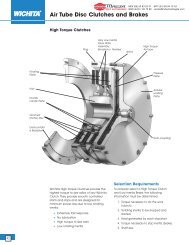
THEORY OF OPERATIONDIST. AUTORIZADO®MEX (55) 53 63 23 31QRO (442) 1 95 72 60MTY (81) 83 54 10 18ventas@industrialmagza.comNexen’s <strong>EN40</strong>-IS Electro-Pneumatic Converter convertscurrent input signals into corresponding pneumaticsignals. Normally the <strong>EN40</strong>-IS is used as part of aNexen-Nireco <strong>Intrinsically</strong> <strong>Safe</strong> Tension Control System,or as an independent Electo-Pneumatic Converter,controlled by an external signal from a Process Controller,using an appropriate Zenier Barrier.<strong>EN40</strong>-IS balances the force of a moving coil with theforce of a poppet valve, and amplifies the air flow andpneumatic pressure passing through a fixed orifice bymeans of the booster relay, resulting in a pneumaticpressure proportional to the electric signal.When current flows through the moving coil, a downwardforce is induced proportionally to the current value. Thisreduces the clearance between the poppet and seat,causing back pressure to rise (See Figure 1).Back pressure is too low to use as an output, but is usedas the pilot pressure for the Booster Section, increasingboth pressure and volume to provide a usable output.SpringPlateFixedOrificeFIGURE 1MovingCoilPermanentMagnetPoppetSeatPilot <strong>Pressure</strong>ChamberINSTALLATIONNOTE The <strong>EN40</strong>-IS must be mounted vertically within ±15 degrees in a shock and vibration free area.Locate the <strong>EN40</strong>-IS as close as possible to thecontrolled element to guarantee quick precisecontrol (See Figure 2).FIGURE 2WALL MOUNTING1. Drill two 0.28 In. [10 mm] diameter holes 4.57 In.[166 mm] apart in the Mounting Panel.2. Secure the <strong>EN40</strong>-IS to the Mounting Panel using thecap screws provided in parts bag.FORM NO. L-<strong>20113</strong>-E-05012
BASE MOUNTINGDIST. AUTORIZADO®MEX (55) 53 63 23 31QRO (442) 1 95 72 60MTY (81) 83 54 10 18ventas@industrialmagza.com1. Remove the <strong>EN40</strong>-IS wall mounting bracket from the<strong>EN40</strong>-IS.2. Secure the <strong>EN40</strong>-IS to the base using the Bracketsand M5 cap screws provided (See Figure 3).FIGURE 3MANIFOLD MOUNTING1. Remove the <strong>EN40</strong>-IS wall mounting bracket from the<strong>EN40</strong>-IS.2. Plug the INLET and OUTLET ports with the providedPlugs.3. Remove the Plugs from the underside of the <strong>EN40</strong>-IS and install the provided O-rings (See Figure 4).4. Secure the <strong>EN40</strong>-IS to the Manifold using theprovided Brackets and M5 cap screws (See Figures5 and 6).FIGURE 4Remove PlugsandinstallO-ringsFIGURE 5FIGURE 63 FORM NO. L-<strong>20113</strong>-E-0501
ELECTRICAL CONNECTIONSDIST. AUTORIZADO®MEX (55) 53 63 23 31QRO (442) 1 95 72 60MTY (81) 83 54 10 18ventas@industrialmagza.com1. Remove the cover from the <strong>EN40</strong>-IS and remove theWARNING Tag from the INPUT terminals (SeeFigure 7).CAUTIONAlways short the INPUT terminals whentransporting or storing the <strong>EN40</strong>-IS.RemoveWARNINGTag2. Using customer supplied 18AWG wire, connect<strong>EN40</strong>-IS to Zenier Barrier, routing wire throughthreaded conduit hole on side of <strong>EN40</strong>-IS.3. Connect the <strong>EN40</strong>-IS Ground to a suitable ground.CAUTIONAlways observe the polarity of the<strong>EN40</strong>-IS terminals. The Driving Designis the logic diagram used with theTC240-IS System (See Figure 8). If theTC240-IS is not used, refer to theSinking Design (See Figure 9).FIGURE 7FIGURE 8Driving DesignFIGURE 9Sinking DesignFORM NO. L-<strong>20113</strong>-E-05014
AIR LINE CONNECTIONDIST. AUTORIZADO®MEX (55) 53 63 23 31QRO (442) 1 95 72 60MTY (81) 83 54 10 18ventas@industrialmagza.comNexen’s <strong>EN40</strong>-IS requires clean, pressure regulated airfor maximum performance and long life. Your NexenDistributor carries filters and regulators specificallydesigned to operate with Nexen products.A Pre-filter (rated at 5.0 micron) removes large particlesfrom the air supply. The Coalescing Filter (0.04 micron orless) is then used to filter the air before it enters the<strong>EN40</strong>-IS (See Figures 10 and 11).CAUTIONWhen lubrication is required for the finalcontrol element, a pilot operated regulator(or booster) must be used to segregatethe <strong>EN40</strong>-IS from the lubricatedair during exhaust or pressure reductionphases (See Figure 11).FIGURE 10FIGURE 115 FORM NO. L-<strong>20113</strong>-E-0501
ADJUSTMENTDIST. AUTORIZADO®MEX (55) 53 63 23 31QRO (442) 1 95 72 60MTY (81) 83 54 10 18ventas@industrialmagza.comNexen’s <strong>EN40</strong>-IS has been factory adjusted and shouldnot require further adjustment.The <strong>EN40</strong>-IS is available in three models. The modeldesignation can be found on the serial number tag,located on the front of the <strong>EN40</strong>-IS. If adjustments arerequired, determine the model and refer to Table 1 for thecorrect values called out in the adjustment procedure.TABLE 1MODEL<strong>EN40</strong>-1AS<strong>EN40</strong>-1BS<strong>EN40</strong>-1DSImin(mADC) 4 4 4Imax(mADC) 202020Pmin(psi) 1.51.53Pmax(psi) 578515Psup(psi) 7010020ZERO ADJUSTMENT1. Remove the Gauge Port Plug and install a suitable airpressure gauge.2. Set Controller Mode Switch to Manual.Rotate to adjustoutput to Pmin3. Using the Manual Control Pot located on Controller,adjust the Controller output to Imin.4. Remove the Zero Adj. Cover.5. Using a screwdriver, adjust the <strong>EN40</strong>-IS output toPmin (rotate clockwise to increase, counterclockwise to decrease) (See Figure 12).NOTE: Do not adjust pressure to 0 psi. There mustbe positive pressure at the Poppet and Seat.6. Replace the Zero Adj. Cover.7. Remove the air pressure gauge and reinstall theGauge Port Plug.FIGURE 12Gauge PortPlugSPAN ADJUSTMENTNOTE: Supply pressure must be Psup.1. Perform Zero Adjustment.NOTE: Do not remove air pressure gauge.2. Using the Manual Control Pot located on Controller,adjust the Controller output to Imax.3. Remove the top cover.4. Using a screwdriver, adjust the Span Pot to obtainPmax output (See Figure 13).FIGURE 13Span PotFORM NO. L-<strong>20113</strong>-E-05016
PARTS LISTDIST. AUTORIZADO®MEX (55) 53 63 23 31QRO (442) 1 95 72 60MTY (81) 83 54 10 18ventas@industrialmagza.comDESCRIPTION<strong>EN40</strong>-1AS<strong>EN40</strong>-1BS<strong>EN40</strong>-1DSUpperDiaphragm Assembly272027202720LowerDiaphragm Assembly272127222723OrificePlate266226622662CoilAssembly with Poppet266626662666FIELD WIRING INTRINSIC SAFETYThis barrier effectively isolates the Sensors and Electro-Pneumatic Converter in the hazardous area from theController in the nonhazardous area. These componentsare used to build a tension control system for hazardousareas, as certified by Factory Mutual (FM) to meetrequirements for <strong>Intrinsically</strong> <strong>Safe</strong> Class I, II, and III,Division 1, Groups A, B, C, D, E, F, and G, Nonincendive,Class I, Division 2, Group A, B, C, and D. Suitable forClass II, Division 2, Group G, when connected perHorton Drawing SC-1395 (See Figure 16).7 FORM NO. L-<strong>20113</strong>-E-0501
MAINTENANCEDIST. AUTORIZADO®MEX (55) 53 63 23 31QRO (442) 1 95 72 60MTY (81) 83 54 10 18ventas@industrialmagza.comThere is no scheduled maintenance required for Horton’s<strong>EN40</strong>-IS Electro-Pneumatic Converter.TROUBLESHOOTINGOPERATIONAL CHECK1. Remove the Gauge Port Plug and install a suitable airpressure gauge.2. Apply Psup to inlet port (See Table 1).3. Vary the electrical signal to the <strong>EN40</strong>-IS within therange of 4-20mADC.CLEANING FIXED ORIFICENOTE: If dirt particles are present in the Fixed Orifice,check the condition of Pre-filter and CoalescingFilter. These filters must be kept clean andproperly maintained to prevent clogging of theFixed Orifice.1. Remove the Fixed Orifice Housing (See Figure 14).FixedOrificeHousing2. Remove the O-ring and Orifice Plate (See Figure 15).3. Clean the Fixed Orifice Housing air passage.4. Passing a thin wire through the hole in Orifice Plate,clean the Orifice Plate air passage.FIGURE 14CAUTIONDo not use cleaning solvents to cleanO-rings. Clean O-rings with a clean, drycloth, then apply a thin coat of O-ringlubricant to the O-rings.O-ringOrificePlate5. Install the Orifice Plate and clean O-rings into theFixed Orifice Housing.6. Install the Fixed Orifice Housing onto the <strong>EN40</strong>-IS.a. If the pressure does not vary directly withsignal, reverse the electrical leads.FIGURE 15b. If the pressure is slow to react to changes insignal, clean the Fixed Orifice.FORM NO. L-<strong>20113</strong>-E-05018
DIST. AUTORIZADO®MEX (55) 53 63 23 31QRO (442) 1 95 72 60MTY (81) 83 54 10 18ventas@industrialmagza.comFIGURE 16Field Wiring Intrinsic <strong>Safe</strong>ty (SC-1395)9 FORM NO. L-<strong>20113</strong>-E-0501
WARRANTIESDIST. AUTORIZADO®MEX (55) 53 63 23 31QRO (442) 1 95 72 60MTY (81) 83 54 10 18ventas@industrialmagza.comWarrantiesNexen warrants that the Products will be free from any defects in material or workmanship for a period of 12 monthsfrom the date of shipment. NEXEN MAKES NO OTHER WARRANTY, EXPRESS OR IMPLIED, AND ALL IMPLIEDWARRANTIES, INCLUDING WITHOUT LIMITATION, IMPLIED WARRANTIES OF MERCHANTABILITY ANDFITNESS FOR A PARTICULAR PURPOSE ARE HEREBY DISCLAIMED. This warranty applies only if (a) the Producthas been installed, used and maintained in accordance with any applicable Nexen installation or maintenance manualfor the Product; (b) the alleged defect is not attributable to normal wear and tear; (c) the Product has not been altered,misused or used for purposes other than those for which it was intended; and (d) Buyer has given written notice of thealleged defect to Nexen, and delivered the allegedly defective Product to Nexen, within one year of the date ofshipment.Exclusive RemedyThe exclusive remedy of the Buyer for any breach of the warranties set out above will be, at the sole discretion of Nexen,a repair or replacement with new, serviceably used or reconditioned Product, or issuance of credit in the amount of thepurchase price paid to Nexen by the Buyer for the Products.Limitation of Nexen’s LiabilityTO THE EXTENT PERMITTED BY LAW NEXEN SHALL HAVE NO LIABILITY TO BUYER OR ANY OTHER PERSONFOR INCIDENTAL DAMAGES, SPECIAL DAMAGES, CONSEQUENTIAL DAMAGES OR OTHER DAMAGES OFANY KIND OR NATURE WHATSOEVER, WHETHER ARISING OUT OF BREACH OF WARRANTY OR OTHERBREACH OF CONTRACT, NEGLIGENCE OR OTHER TORT, OR OTHERWISE, EVEN IF NEXEN SHALL HAVEBEEN ADVISED OF THE POSSIBILITY OR LIKELIHOOD OF SUCH POTENTIAL LOSS OR DAMAGE. For all ofthe purposes hereof, the term “consequential damages” shall include lost profits, penalties, delay images, liquidateddamages or other damages and liabilities which Buyer shall be obligated to pay or which Buyer may incur based upon,related to or arising out of its contracts with its customers or other third parties. In no event shall Nexen be liable forany amount of damages in excess of amounts paid by Buyer for Products or services as to which a breach of contracthas been determined to exist. The parties expressly agree that the price for the Products and the services wasdetermined in consideration of the limitation on damages set forth herein and such limitation has been specificallybargained for and constitutes an agreed allocation of risk which shall survive the determination of any court ofcompetent jurisdiction that any remedy herein fails of its essential purpose.Limitation of DamagesIn no event shall Nexen be liable for any consequential, indirect, incidental, or special damages of any nature whatsoever,including without limitation, lost profits arising from the sale or use of the Products.Warranty Claim ProceduresTo make a claim under this warranty, the claimant must give written notice of the alleged defect to whom the Productwas purchased from and deliver the Product to same within one year of the date on which the alleged defect firstbecame apparent.Nexen Group, Inc.560 Oak Grove ParkwayVadnais Heights, MN 55127800.843.7445Fax: 651.286.1099www.nexengroup.comISO 9001 CertifiedFORM NO. L-<strong>20113</strong>-E-050110