Hydrodynamic Fine-Tuning of a Pentamaran for High-Speed Sea ...
Hydrodynamic Fine-Tuning of a Pentamaran for High-Speed Sea ...
Hydrodynamic Fine-Tuning of a Pentamaran for High-Speed Sea ...
- No tags were found...

You also want an ePaper? Increase the reach of your titles
YUMPU automatically turns print PDFs into web optimized ePapers that Google loves.
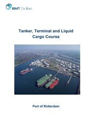
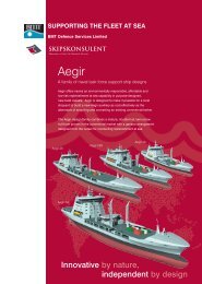
International Conference on Fast <strong>Sea</strong> TransportationFAST’2005, June 2005, St.Petersburg, Russia<strong>Hydrodynamic</strong> <strong>Fine</strong>-<strong>Tuning</strong> <strong>of</strong> a <strong>Pentamaran</strong> <strong>for</strong><strong>High</strong>-<strong>Speed</strong> <strong>Sea</strong> Transportation ServicesEd Dudson, * Stefan Harries *** BMT Nigel Gee and Associates Ltd, Floors 1-3, Building 14, Shamrock Quay,William Street, Southampton, Hampshire, SO14 5 QL, UKEDudson@ngal.co.uk** FRIENDSHIP-Systems GmbH, Benzstr. 2, D-14482 Potsdam, Germanyharries@FRIENDSHIP-Systems.comABSTRACTThis paper discusses the hydrodynamic optimization <strong>of</strong> the central hull <strong>of</strong> a 290m <strong>Pentamaran</strong> <strong>for</strong> <strong>Sea</strong>Bridge inorder to maximize the speed <strong>of</strong> the vessel with a pre-determined machinery package. The optimization <strong>of</strong> thecentral hull was per<strong>for</strong>med by combining the parametric CAD program FRIENDSHIP-Modeler with the CFDcode SHIPFLOW via the generic optimization tool FRIENDSHIP-Optimizer. A scale model <strong>of</strong> the optimizedcentral hull was made and a series <strong>of</strong> resistance tests undertaken to verify the accuracy <strong>of</strong> the CFD calculationsand to prove the validity <strong>of</strong> the optimization.Figure 1: Rendering <strong>of</strong> the <strong>Sea</strong>Bridge <strong>Pentamaran</strong>INTRODUCTIONThe vessel is a 290m, 6500t Dwt high speed<strong>Pentamaran</strong> Ro-Pax vessel designed <strong>for</strong> <strong>Sea</strong>BridgeInternational Inc. The vessel is powered by a DieselElectric Propulsion plant in combination withwaterjets. A rendering <strong>of</strong> the vessel is shown inFigure 1.The <strong>Sea</strong>Bridge approach uses the sea to complementexisting land-based travel on selected routes to attractfreight movements away from overcrowdedhighways, <strong>for</strong> at least part <strong>of</strong> the journey from shipperto receiver. By using the sea as a bridge, <strong>Sea</strong>Bridgeintends to transport more goods, with lessenvironmental impact, at lower cost, and in a shortertime frame than any comparable transportationalternative available today.<strong>Sea</strong> transport at 40 knots and higher requires theutmost ef<strong>for</strong>t to reduce energy consumption. Thework presented in this paper is, there<strong>for</strong>e, dedicatedto the systematic fine-tuning <strong>of</strong> the <strong>Pentamaran</strong>’scentral hull. The volume, position and shape <strong>of</strong> thesidehulls were not considered as part <strong>of</strong> this study ,since they had been subject to previous investigationsin which a favourable method <strong>for</strong> designing thesidehull configuration had already been established.For the central hull, <strong>for</strong>mal strategies to improve thecalm water hydrodynamic per<strong>for</strong>mance wereemployed. A sophisticated parametric definition <strong>of</strong>the hull shape was established within the ComputerAided Design (CAD) tool FRIENDSHIP-Modeler <strong>for</strong>an efficient and effective <strong>for</strong>m optimization.The repeating stages <strong>of</strong> geometric modelling,hydrodynamic simulation, per<strong>for</strong>mance assessmentand systematic variation were integrated into a
worship, trans<strong>for</strong>ming ministry, food, fellowship and anointing! Robyn Vincent will be the mainspeaker, and Karen Vaughn, Emma Colbert and Elaine Priestly will all be ministering inworkshops. The gathering will begin at 10 AM with worship, and run through the afternoon andwill end with an anointing service! There is no cost to attend, so be sure to invite your friends tojoin you. So we can best prepare <strong>for</strong> lunch, please register with Lori Shelbourn at the back <strong>of</strong> theTabernacle this Sunday morning, or email her at wilori[at]live[dot]com. For those <strong>of</strong> you whoare not able to join us onsite, this gathering will be available by live webcast.Blessings,Chuck D. PierceIf you would like to give towards the ongoing work <strong>of</strong> this ministry, you can donate online (clickHERE), by calling 1 (888) 965-1099 or 1 (940) 382-7231, or sending a gift to PO Box 1601,Denton TX 76202.Key Resources to Help You Break Forth in a New Way!Be Revived Anointing Oil and CandleRevival is in earth's atmosphere! Because the anointing breaks the yoke, we sought the Lord onthe ingredients needed <strong>for</strong> a revival fire anointing oil and candle. The first aspect <strong>of</strong> Revived is"awakening". We use costmary, an original herb used by the colonists to stay alert andawake. The second ingredient we incorporate is pomegranate, representing healing, overcomingand prosperity. The third ingredient is "harvest". This is a mixture <strong>of</strong> the seven species <strong>of</strong> Israelwhich represent the fullness <strong>of</strong> unlocking the harvest fields. There is a boldness that God isbringing on His people to pray over others. We must come alive and be bold witnesses in thishour. Be revived and use this oil to "break the yoke" as you minister to others.Roll-on Anointing Oil $10; Candle: $12; Roll-on Anointing Oil + Candle: $20.The Portal!
Installing waterjets on a vessel requires a submergedtransom. A submerged transom on a vessel travellingat relatively low Froude numbers, as with the<strong>Sea</strong>bridge, can have a significant impact on the totalresistance <strong>of</strong> the vessel. BMT Nigel Gee andAssociates Ltd have, there<strong>for</strong>e, spent a significantamount <strong>of</strong> time developing the optimum transomdesign <strong>for</strong> a waterjet propelled vessel operating at lowFroude numbers. The design is developed around thewaterjets and the requirements to avoid waterjetventilation in waves. A sketch <strong>of</strong> the transom designis shown in Figure 5.Figure 5: Gulley transom designFigure 3: General Arrangement <strong>of</strong> the <strong>Sea</strong>Bridge<strong>Pentamaran</strong>1.4. Machinery ArrangementThe vessel is propelled by a diesel electric propulsionsystem which provides <strong>for</strong> most economic andflexible power plant installation <strong>for</strong> this application.Medium speed diesel engines burning heavy fuel oilare situated around amidships.Five waterjets are driven by tandem electric motorspositioned close to the transom. The waterjets andelectric motors are configured such that with a singlejet out <strong>of</strong> operation, the four remaining waterjets canabsorb 100% <strong>of</strong> the generated power, resulting inminimal speed loss. A sketch <strong>of</strong> the machineryarrangement is shown in Figure 4.Figure 4: Machinery Arrangement2. PARAMETRIC MODELLING OF THECENTRAL HULL2.1. Parametric ApproachIn order to generate and vary functional surfaces <strong>of</strong>complex shape such as ship hull <strong>for</strong>ms with a degree<strong>of</strong> freedom suitable <strong>for</strong> optimization, a parametricapproach ought to be followed. The essence <strong>of</strong> aparametric definition is that a context-dependent andsolution-oriented description is established, whichallows production <strong>of</strong> those shapes that are beneficialto per<strong>for</strong>mance while still acceptable with regard tothe many constraints.The FRIENDSHIP-Modeler grants a high-leveldefinition <strong>of</strong> hull shapes via <strong>for</strong>m parameters such asbeam, deadrise, draft, entrance angles, sectional areasetc. and was there<strong>for</strong>e selected <strong>for</strong> the optimization <strong>of</strong>the <strong>Pentamaran</strong>’s central hull. For details see(Harries and Abt, 1999), (Harries et al, 2001) and(Harries and Heimann, 2003), further in<strong>for</strong>mation anddownloads are available at www.FRIENDSHIP-Systems.com.2.2. Form ParametersThe shape <strong>of</strong> the <strong>Pentamaran</strong>’s central hull called <strong>for</strong>a specific parameterization which was developed byFRIENDSHIP-Systems on the basis <strong>of</strong> the baselinedesign by BMT Nigel Gee and Associates Ltd, seeFigure 6. The <strong>for</strong>m features were closely examined,
<strong>for</strong> instance via curvature plots, and suitable <strong>for</strong>mparameters were identified.Figure 8: Form parameters <strong>for</strong> definition <strong>of</strong> sectionFigure 6: Curvature plot <strong>of</strong> the baseline designFigure 7: Hull <strong>for</strong>m and basic descriptors <strong>of</strong> the <strong>Sea</strong>BridgeFigure 7 depicts the central hull generated via theFRIENDSHIP-Modeler. The figure shows importantshape descriptors, namely the basic curves which aredetermined from small sets <strong>of</strong> parameters and which,in turn, provide input <strong>for</strong> surface generation. Selected<strong>for</strong>m parameters which define a typical section areillustrated in Figure 8. Note that data from the spacecurves presented in Figure 7 appear here in their planand pr<strong>of</strong>ile components, respectively.Special features <strong>of</strong> the stern region are presented inFigure 9 – compare to Figure 5 – while the topology<strong>of</strong> the surface patchwork is shown in Figure 10.Figure 9: Special features <strong>of</strong> stern region(marker shows area <strong>of</strong> influenceif parameter assume non-zero values)
Figure 10: Surface patches <strong>of</strong> parametric modelAn important task during an optimization is thecontrol and monitoring <strong>of</strong> design constraints, see (Abtet al, 2004). The design displacement <strong>for</strong> instancewas fixed at 30000 t. This constitutes an equalityconstraint which could be handled directly within theFRIENDSHIP-Modeler by utilizing the areain<strong>for</strong>mation from the sectional area curve as input <strong>for</strong>shape generation. Since the aft body <strong>of</strong> the<strong>Pentamaran</strong>’s central hull featured little freedom <strong>for</strong>displacement changes a special mechanism needed tobe developed: Firstly, the aft body was generatedwith respect to the dominating positional constraints<strong>of</strong> the propulsion unit. Secondly, the actual sectionalarea curve was computed <strong>for</strong> the aft body and thencontinued <strong>for</strong>ward in compliance with thedisplacement constraint. Finally, the sectional areacurve was utilized <strong>for</strong> the <strong>for</strong>ward body as parametricinput. In this way, infeasible designs with regard todisplacement could be readily avoided2.3. Form VariationsFigure 11 illustrates a representative shape variationout <strong>of</strong> the many which were studied. Here thedeadrise was systematically changed from zero to 14degrees.Figure 12 gives an impression about the scope <strong>of</strong><strong>for</strong>m variations <strong>for</strong> the aft region. Theparameterization allowed a smooth transition fromthe Gulley transom to a more conventionalconfiguration. The Gulley however was eventuallyfavoured <strong>for</strong> the final design (compare to section 1.4).Figure 11: Parametric variation via changes indeadrise
test results had been available <strong>for</strong> a similar hullreasonable confidence could be established withregard to the flow code’s ability to handle thedifficult flow phenomena aft <strong>of</strong> the Gulley transom.The CFD based prediction resulted in resistanceestimates below model test results, however, theresistance characteristics were well-captured by CFD<strong>for</strong> the speed range in question.3.2. Optimization ApproachOften an optimization programme is beneficiallysubdivided into two phases <strong>of</strong> design exploration. Inthe <strong>for</strong>mer, a large set <strong>of</strong> designs are distributed in thesearch domain while in the latter promisingcandidates <strong>of</strong> the first phase are further improved in atargeted variation.Figure 12: Parametric variations <strong>of</strong> stern region3. OPTIMIZATION3.1. <strong>Hydrodynamic</strong> AnalysisThe calm water hydrodynamics was <strong>of</strong> prime concernin this study, there<strong>for</strong>e the total resistance was chosento be the objective <strong>of</strong> the optimization. The non-linearwave resistance was assessed by means <strong>of</strong> thepotential module <strong>of</strong> the well-known SHIPFLOWcode. The wave making resistance was determined bypressure int egration and wave cut analyses. Viscouseffects were accounted <strong>for</strong> via the ITTC friction lineand a suitably selected <strong>for</strong>m factor.A systematic panelization study was per<strong>for</strong>med inorder to select a good compromise between accuracy,computational demands and robustness. Since modelFigure 13 shows the outcome <strong>of</strong> a Design-<strong>of</strong>-Experiment (DoE) which represents the firstexploration phase. A fleet <strong>of</strong> 1000 hull <strong>for</strong>ms weregenerated, 527 <strong>of</strong> which passed all constraints andwere successfully evaluated by the flow code. A set<strong>of</strong> 21 <strong>for</strong>m parameters were chosen as free variables<strong>for</strong> the DoE. In Figure 13 all valid designs are rankedwith respect to wave pattern resistance calculatedfrom a transverse wave cut analysis. The dashed lineindicates the per<strong>for</strong>mance <strong>of</strong> the baseline. FromFigure 13 it can be clearly seen that a substantialnumber <strong>of</strong> designs have lower resistance than thebaseline. Naturally, many designs also are rankedinferior.Based on the DoE further optimization runs wereundertaken using the Tangent <strong>Sea</strong>rch Method byHilleary. This deterministic strategy follows a Hookeand-Jeevesdirect search in connection with a feasibledirection approach as soon as inequality constraintsFigure 13: Resistance estimates sorted by wave pattern resistance(abscissa: accumulated number <strong>of</strong> designs, ordinate: various resistance estimates)
Figure 14: History <strong>of</strong> final optimization run(abscissa: sequence <strong>of</strong> design variants, ordinate: combined and normalized objective function)Figure 15: Wave pattern <strong>of</strong> baseline and optimized hull <strong>Sea</strong>Final9.0074are violated.Figure 14 features the optimization history <strong>of</strong> thefinal run from which the best design was identified(<strong>Sea</strong>Final9.0074).3.2. Selected ResultsFigure 15 compares the wave patterns <strong>of</strong> the baselineand the optimized central hull, respectively. (Thefigure corresponds to the be<strong>for</strong>e-and-after pictures <strong>of</strong>a plastic surgery candidate.) The wave resistancefrom pressure integration is reduced by about 13.8 %which yields an improvement <strong>of</strong> about 5.6 % in totalresistance.4. EXPERIMENTAL VALIDATION4.1. Test ProgramEstimates from the CFD analysis suggested a vesselresistance lower than originally predicted (see alsosection 3.1). The optimized hull also indicated afurther reduction in wave resistance. In order toconfirm the resistance predictions from CFD a set <strong>of</strong>calm water model tests was conducted at
MARINTEK in Norway. Figure 16 shows aphotograph from the tests.Figure 16: Resistance tests at 40 knots4.2. ResultsFigure 17 presents wave cuts from both CFD andexperiment, 0 and 1 being the position <strong>of</strong> the <strong>for</strong>wardand the aft perpendicular, respectively. Goodagreement in the phase can be seen while theamplitudes from the CFD are smaller than those fromthe experiments. One possible explanation <strong>for</strong> thediscrepancies is that the wave cut was measured quitefar from the hull which may have caused numericaldamping in the numerical simulation.The model test results confirmed the improvement inresistance over the baseline. Figure 18 compares thefull scale resistance <strong>for</strong> the optimized hull asmeasured from model tests against the predictedresistance <strong>for</strong> the baseline hull at 30000 t.Figure 17: Wave cut from CFD and model testsFigure 18: Model test results <strong>for</strong> three displacements5. CONCLUSIONSThe process <strong>of</strong> parametric optimisation through CFDprovides the designer with a tool which significantlyenhances the usability <strong>of</strong> CFD and results in a trulyoptimized hull, rather than an improved hull.Naturally, the user’s knowledge and understanding <strong>of</strong>CFD is vital as well as an appreciation <strong>of</strong> the limits <strong>of</strong>the flow code. A suitable parameterization <strong>of</strong> theproblem is essential to reduce the number <strong>of</strong> freevariables and, consequently, the overall number <strong>of</strong>designs <strong>for</strong> which a CFD simulation is to beundertaken. The application <strong>of</strong> <strong>for</strong>mal strategies t<strong>of</strong>ine-tune the <strong>Pentamaran</strong>’s central hull <strong>for</strong> high-speedsea transportation services proved to be successful.ACKNOWLEDGMENTSThe authors would like to thank <strong>Sea</strong>BridgeInternational Inc. <strong>for</strong> their support in publishing thispaper. Further in<strong>for</strong>mation on the vessel and conceptmay be found at www.seabridgeferries.com.REFERENCES1. Abt, C.; Harries, S.; Hochkirch, K., ConstraintManagement <strong>for</strong> Marine Design Applications, 9 thInternational Symposium on Practical Design <strong>of</strong>Ships and Other Floating Structures, Lübeck-Travemünde, September 2004.2. Dudson, E.; Gee, N., Optimisation <strong>of</strong> the<strong>Sea</strong>keeping and Per<strong>for</strong>mance <strong>of</strong> a 40 Knot<strong>Pentamaran</strong> Container Vessel, 6 th InternationalConference on Fast <strong>Sea</strong> Transportation,Southampton, September 2001.3. Dudson, E.; Rambech, H.J.; Wu, M.K.,Determination <strong>of</strong> Wave Bending Loads on a 40 Knot,Long Slender Open Topped Containership throughModel Tests and <strong>Hydrodynamic</strong> Calculations withParticular Reference to the Effects <strong>of</strong> Hull Flexibilityon Fatigue Life, 6 th International Conference on Fast<strong>Sea</strong> Transportation, Southampton, September 2001.4. Harries, S.; Heimann, J., Optimization <strong>of</strong> theWave-making Characteristics <strong>of</strong> Fast Ferries, 7 thInternational Conference on Fast <strong>Sea</strong> Transportation,Ischia (Golf <strong>of</strong> Naples), October 2003.5. Harries, S.; Valdenazzi, F.; Abt, C.; Viviani, U.,Investigation on Optimization Strategies <strong>for</strong> the<strong>Hydrodynamic</strong> Design <strong>of</strong> Fast Ferries, 6 thInternational Conference on Fast <strong>Sea</strong> Transportation,Southampton, September 2001.6. Harries, S.; Abt, C., Formal <strong>Hydrodynamic</strong>Optimization <strong>of</strong> a Fast Monohull on the Basis <strong>of</strong>Parametric Hull Design, 5 th International Conferenceon Fast <strong>Sea</strong> Transportation, <strong>Sea</strong>ttle, August 1999
AUTHORS’ BIOGRAPHYEd Dudson graduated from the University <strong>of</strong>Southampton in 1990 and joined Nigel Gee andAssociates the same year where he has workedcontinuously with the exception <strong>of</strong> a year’s sabbaticalin MARINTEK. He is Director <strong>of</strong> Ship Design <strong>for</strong>BMT Nigel Gee and Associates Ltd. In October 2004he was elected to the board <strong>of</strong> Directors <strong>of</strong> BMTNigel Gee and Associates Ltd. Ed Dudson is aChartered Engineer and Member <strong>of</strong> the RoyalInstitute <strong>of</strong> Naval Architects.Stefan Harries is managing director <strong>of</strong> FRIENDSHIP-Systems, a design consultancy that he co-founded in2001. He studied mechanical engineering at theTechnical University <strong>of</strong> Darmstadt and navalarchitecture at both the University <strong>of</strong> Michigan (MSEin 1990) and the Technical University Berlin(Diplom-Ingenieur in 1992). In 1998 he received hisdoctoral degree from TU Berlin, following five yearsas scientist with Pr<strong>of</strong>. Nowacki. He was head <strong>of</strong>Marine <strong>Hydrodynamic</strong>s at the Berlin Model BasinVWS (1998 to 2000) be<strong>for</strong>e he became head <strong>of</strong> TUBerlin's research unit Design and Operation <strong>of</strong>Marine Systems (2001 to 2003). Since 2004 he isfull-time with FRIENDSHIP-Systems but keeps to beassociated with TU Berlin as lecturer <strong>for</strong> ComputerAided Engineering.