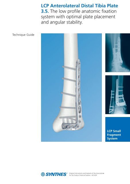
LCP Anterolateral Distal Tibia Plate 3.5. The low profile anatomic ...
LCP Anterolateral Distal Tibia Plate 3.5. The low profile anatomic ...
LCP Anterolateral Distal Tibia Plate 3.5. The low profile anatomic ...

You also want an ePaper? Increase the reach of your titles
YUMPU automatically turns print PDFs into web optimized ePapers that Google loves.
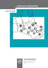
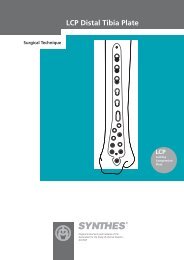
Features– Anatomically shaped– Two different plate designs to fit right or left tibia(indicated with R or L on plate)– Shaft holes accept locking screws 3.5 mm, cortexscrews 3.5 mm and cancellous bone screws 4.0 mm– Head holes accept locking screws 3.5 mm, cortexscrews 2.7 mm and 3.5 mm and cancellous bonescrews 4.0 mm.– 3.6 mm shaft thickness tapers to 2.5 mm distally– Tapered tip for submuscular insertion– Screw heads are recessed in the plate to minimize screwprominenceBenefits– <strong>Distal</strong> locking screws provide support for the articularsurface– Targeted locking for Volkman's triangle and the Chaputfragment– <strong>The</strong> head of the plate is designed to provide a <strong>low</strong> <strong>profile</strong>construct when using locking screws or cortex screws 2.7 mm, resulting in less soft tissue irritation.– 60° twist in shaft is contoured for the distal tibia anatomy:less plate contouring is required.Elongated hole aidsin plate positioningFour distal head holesangle 7º inferiorly tocapture the posteriormalleolusProximal hole forcompression ordistraction with thearticulated tensiondevice<strong>The</strong> shaft includes twodistal locking holes andcombi-holes.Three Kirschner wireholes in the head,parallel to the joint,accept Kirschner wiresto temporarily fixfragments and showproximity to the jointSynthes 3
AO ASIF PrinciplesIn 1958, the AO ASIF (Association for the Study of Internalfixation) formulated four basic principles, which have becomethe guidelines for internal fixation. 1 <strong>The</strong>se principles,as applied to the <strong>LCP</strong> <strong>Anterolateral</strong> <strong>Distal</strong> <strong>Tibia</strong> <strong>Plate</strong> 3.5, are:Anatomic reductionAnatomic plate <strong>profile</strong> and four parallel screws near the jointassist reduction of metaphysis to diaphysis to restore alignmentand functional anatomy. Anatomic reduction ismandatory for intra-articular fractures to restore joint congruency.Stable fixation<strong>The</strong> combination of conventional and locking screws offersoptimum fixation regardless of bone density.Preservation of blood supplyLimited-contact plate design reduces plate-to-bone contactand helps to preserve the periosteal blood supply.Early mobilization<strong>Plate</strong> features combined with AO technique create anenvironment for early bone healing, expediting return tofunction.1M.E. Müller, M. Allgöwer, R. Schneider, H. Willenegger. AO Manual of InternalFixation. 3rd Edition. Berlin: Springer-Verlag. 1991.4 Synthes <strong>LCP</strong> <strong>Anterolateral</strong> <strong>Distal</strong> <strong>Tibia</strong> <strong>Plate</strong> 3.5 Technique Guide
Indications<strong>The</strong> <strong>LCP</strong> <strong>Anterolateral</strong> <strong>Distal</strong> <strong>Tibia</strong> <strong>Plate</strong> 3.5 is indicated for:– Extra-articular and simple intra-articular distal tibiafractures– <strong>Distal</strong> tibia fracture, percutaneous or reducible by limitedarthrotomy– <strong>Distal</strong> tibia fracture extending into the diaphyseal areaSynthes 5
Clinical CasesCase 150-year-old male, fall from wallPreop lateral Preop AP Postop lateral Postop APCase 251-year-old female, corrective osteotomyPreop lateral Preop AP Postop lateral Postop AP6 Synthes <strong>LCP</strong> <strong>Anterolateral</strong> <strong>Distal</strong> <strong>Tibia</strong> <strong>Plate</strong> 3.5 Technique Guide
Case 375-year-old male, MVAPreop lateral Preop AP Postop lateral Postop APCase 452-year-old female, MVAPreop lateral Preop AP Postop lateral Postop APSynthes 7
Preoperative Planning1PreparationRequired set (one of the fol<strong>low</strong>ing)182.400 <strong>LCP</strong> Compact Small Fragment InstrumentSet with Locking Screws Stardrive 3.5 mmand Implants (Pure Titanium) in Vario Case182.405 <strong>LCP</strong> Compact Small Fragment InstrumentSet with Locking Screws Stardrive 3.5 mmand Implants (Stainless Steel) in Vario Case182.410 <strong>LCP</strong> Compact Small Fragment InstrumentSet with Locking Screws 3.5 mm andImplants (Pure Titanium) in Vario Case182.415 <strong>LCP</strong> Compact Small Fragment InstrumentSet with Locking Screws 3.5 mm andImplants (Stainless Steel) in Vario CaseOptional sets105.900 Bone Forceps Set117.700 Instrument Set for Large Distractor01.900.022 Extraction Module for Screws 3.5, 4.0 and 4.5 mmOptional instrumentsX92.200 Kirschner Wire 2.0 mm with trocar tipX92.710 Kirschner Wire 1.6 mm with threaded tip309.520 Extraction Screw, conical310.250 Drill Bit 2.5 mm311.430 Handle with Quick Coupling321.120 Tension Device, articulated321.150 Socket Wrench 11 mm323.360 Universal Drill Guide 3.5324.024 Instrument for Temporary Reduction324.031 <strong>Plate</strong> Holder with Thread 3.5 mm324.214 Drill Bit 2.8 mm, with Scale,length 200/100 mm329.040 Bending Iron for <strong>Plate</strong>s 2.4 to 3.5329.050 Bending Iron for <strong>Plate</strong>s 2.4 to 3.5329.300 Bending Press394.350 Large Distractor395.490 Medium DistractorX=2: stainless steelX=4: titaniumComplete the preoperative radiographic assessment and preparethe preoperative plan. Determine plate length and instrumentsto be used. Determine distal screw placement toensure proper screw placement in the metaphysis.8 Synthes <strong>LCP</strong> <strong>Anterolateral</strong> <strong>Distal</strong> <strong>Tibia</strong> <strong>Plate</strong> 3.5 Technique Guide
Position patientPosition the patient supine on a radiolucent operating table.Visualization of the distal tibia under fluoroscopy in both thelateral and AP views is recommended. Elevate the leg on apadded rest with the knee moderately flexed to placementin a neutral position. Place the opposite leg level on tabletop.Warning: <strong>The</strong> direction of locking screws is already determinedfor normal anatomy based on the design of the plate.If manual contouring in the metaphyseal area is necessary,verify new screw trajectories using the Kirschner wire screwplacement verification technique on page 14.Synthes 9
Reduction2Reduce articular surfaceOptional instrument394.350 Large Distractor395.490 Medium DistractorApproachA longitudinal and straight incision should be centered atthe ankle joint, parallel to the fourth metatarsal distally, andbetween the tibia and fibula proximally. Proximal extensionof the incision should end seven or eight centimeters abovethe joint. <strong>Distal</strong>ly the incision can be extended to the level ofthe talonavicular joint, al<strong>low</strong>ing exposure of the talar neck.<strong>The</strong> joint can be exposed using an arthrotomy.Note: <strong>The</strong> superficial peroneal nerve usually crosses thesurgical incision proximal to the ankle joint and should beprotected throughout the surgical procedure.Reduce fracture/articular surfaceTechnique tip: Application of an external fixator or a distractormay facilitate visualization and reduction of the joint.A lateral distractor can be placed from the talar neck to themid-tibia (from lateral to medial) to maximize joint visualizationby distracting and plantar-flexing the talus.<strong>The</strong> articular reduction is confirmed with image intensification.Temporary reduction can be obtained with multipleKirschner wires. Multiple options exist for maintaining thereduction including:– Independent lag screws– Lag screws through the plate– Locking screws through the plateKirschner wires can be placed through the distal end of theplate to assist with temporary maintenance of the reductionand for plate placement.Locking screws do not provide interfragmentary compression;therefore, any desired compression must be achievedwith standard lag screws. <strong>The</strong> articular fractures must bereduced and compressed before fixation of the <strong>LCP</strong> <strong>Anterolateral</strong><strong>Distal</strong> <strong>Tibia</strong> <strong>Plate</strong> 3.5 with locking screws.Technique tip: To verify that independent lag screws willnot interfere with plate placement, evaluate placement intraoperativelywith AP and lateral fluoroscopic images.10 Synthes <strong>LCP</strong> <strong>Anterolateral</strong> <strong>Distal</strong> <strong>Tibia</strong> <strong>Plate</strong> 3.5 Technique Guide
<strong>Plate</strong> Insertion3Insert plateOptional instrument324.031 <strong>Plate</strong> Holder with ThreadOpen the area as necessary to expose the metaphysis.Slide the shaft submuscularly along the lateral tibial cortex,beneath the anterior compartment muscles and neurovascularbundle. Use special care to protect the superficial peronealnerve, which typically crosses under the incision proximalto the ankle joint. <strong>The</strong> distal row of screws will sit justproximal to the joint. Use fluoroscopic imaging during plateplacement in both the AP and lateral planes to ensure a safeimplant location proximally along the lateral tibia.Technique tip: Insert a threaded plate holder into one ofthe distal holes as a handle for insertion.Synthes 11
<strong>Plate</strong> Insertion4Position plate and fix provisionallyOptional instrumentsX92.200 Kirschner Wire 2.0 mm, with trocar tip324.024 Instrument for Temporary Reduction<strong>The</strong> plate may be temporarily held in place using any of thefol<strong>low</strong>ing options. <strong>The</strong>se options also prevent plate rotationwhile inserting the first locking screw:– Instrument for temporary reduction in a screw hole thatwill not immediately be used (as shown in this techniqueguide)– Cortex screw 3.5 mm or cancellous bone screw 4.0 mm in a locking or combi-hole– Standard plate holding forceps– Kirschner wires through the plate– Cortex screw 2.7 mm in one of the distal holesAfter plate insertion, check alignment on the bone using fluoroscopy.Ensure proper reduction before inserting the firstlocking screw. Once locking screws are inserted, further reductionis not possible without loosening the locking screws.Note: This locking plate is precontoured to fit the anterolateraldistal tibia. If the plate contour is changed, it is importantto check the position of the screws in relation to thejoint, using the screw placement verification technique onpage 14.Technique tip: To adjust the plate into final position, inserta Kirschner wire or partially insert a cortex screw or cancellousbone screw into the elongated hole or a combi-hole beforeinserting a locking screw.12 Synthes <strong>LCP</strong> <strong>Anterolateral</strong> <strong>Distal</strong> <strong>Tibia</strong> <strong>Plate</strong> 3.5 Technique Guide
Optional instruments324.214 Drill Bit 2.8 mm, with Scale,length 200/100 mm324.024324.024 Instrument for Temporary Reduction<strong>The</strong> instrument for temporary reduction is placed throughplate holes to push or pull bone fragments in relation to theplate. This instrument can be used for:– Minor varus-valgus adjustment– Translational adjustments– Provisional fixation– Stabilization of plate-bone orientation during insertion ofthe first screws– Alignment of segmental fragmentsConnect the instrument for temporary reduction to a powerdrive and place it in the desired hole. With the nut in thehighest position possible, begin power insertion of the instrumentfor temporary reduction into the near cortex. Stopinsertion before the end of the threaded portion meets theplate surface. Attempting to advance beyond this point maycause screw threads to strip in the bone.Remove the power tool and begin tightening the nut towardthe plate while monitoring progress under C-arm. Stopwhen the desired reduction is achieved.Synthes 13
Screw Insertion5Option: screw placement verificationInstrumentsX92.710 Kirschner Wire 1.6 mm with threadedtip310.284 <strong>LCP</strong> Drill Bit 2.8 mm323.027 <strong>LCP</strong> Drill Sleeve 3.5, for Drill Bits 2.8 mm323.055 Centering Sleeve for Kirschner Wire 1.6 mm323.060 Direct Measuring Device for Kirschner Wire 1.6 mmSince the direction of the locking screw depends on the contourof the plate, final screw position may be verified withKirschner wires before insertion. This becomes especially importantwhen the plate has been manually contoured, appliednear the joint, or for non-standard anatomy.With the <strong>LCP</strong> drill sleeve in the desired locking hole, insertthe centering sleeve into the drill sleeve.Insert a 1.6 mm threaded Kirschner wire through the centeringsleeve and drill to the desired depth.Verify Kirschner wire placement under image intensificationto determine if final screw placement will be acceptable.Important: <strong>The</strong> Kirschner wire position represents the finalposition of the locking screw. Confirm that the Kirschnerwire does not enter the joint.Measure for screw length by sliding the tapered end of thedirect measuring device over the Kirschner wire down to thecentering sleeve.Remove the direct measuring device, Kirschner wire andcentering sleeve, leaving the drill sleeve in place.Use the 2.8 mm drill bit to drill. Remove the drill sleeve.Insert the appropriate length locking screw.14 Synthes <strong>LCP</strong> <strong>Anterolateral</strong> <strong>Distal</strong> <strong>Tibia</strong> <strong>Plate</strong> 3.5 Technique Guide
6Insert screws in distal fragmentInstruments310.284 <strong>LCP</strong> Drill Bit 2.8 mm323.027 <strong>LCP</strong> Drill Sleeve 3.5, for Drill Bits 2.8 mm314.115 Screwdriver Stardrive314.116 Screwdriver Shaft Stardrive314.070 Screwdriver hexagonal314.030 Screwdriver Shaft hexagonal319.010 Depth Gauge for Screws511.770 or Torque Limiter511.773Determine the combination of screws to be used for fixation.If a combination of locking and cortex screws is used,cortex screws should be inserted first to pull the plate to thebone.Note: To secure the plate to the tibia prior to locking screwinsertion, it is recommended to pull the plate to the boneusing a cortex screw or the Instrument for Temporary Reduction(324.024).If a locking screw is used as the first screw, be sure thefracture is reduced and the plate is held securely to thebone. This prevents plate rotation as the screw is locked tothe plate.Synthes 15
Screw InsertionLocking screw insertion– Insert the drill sleeve into a locking hole or combi-holeuntil fully seated.– Use the 2.8 mm drill bit to drill to the desired depth.– Remove the drill sleeve.– Use the depth gauge to determine screw length.– Insert screw.Insert the locking screw under power, using the torque limiterand the screwdriver shaft, or insert it manually, using thescrewdriver. Hold the plate securely on the bone to preventplate rotation as the screw is locked to the plate.Note: When using the torque limiter, the screw is securelylocked into the plate when a “click” is heard.Warning: Never use the screwdriver shaft directly withpower equipment unless using a torque limiter.16 Synthes <strong>LCP</strong> <strong>Anterolateral</strong> <strong>Distal</strong> <strong>Tibia</strong> <strong>Plate</strong> 3.5 Technique Guide
AlternativeInstruments323.027 <strong>LCP</strong> Drill Sleeve 3.5, for Drill Bits 2.8 mm324.214 Drill Bit 2.8 mm, with Scale,length 200/100 mmInstead of using the <strong>LCP</strong> drill bit and depth gauge, the drillbit with scale can be used for drilling the hole and determiningthe required screw length.7Option: articulated tension deviceInstrument321.120 Tension Device, articulatedOnce reduction is satisfactory, and if it is appropriate basedon fracture morphology, the plate can be loaded in tensionusing the articulated tension device .Note: In simple fracture patterns, the articulated tensiondevice may facilitate <strong>anatomic</strong> reduction. This device may beused to generate either compression or distraction.Synthes 17
Screw Insertion8Insert screws in proximal fragmentA Non-locking screwsInstruments310.250 Drill Bit 2.5 mm323.360 Universal Drill Guide 3.5314.070 Screwdriver hexagonal314.030 Screwdriver Shaft hexagonal319.010 Depth GaugeUse the drill bit through the universal drill guide to predrillthe bone. For the neutral position, press the drill guide downin the nonthreaded hole. To obtain compression, place thedrill guide at the end of the nonthreaded hole away fromthe fracture (do not apply downward pressure on thespring-loaded tip).Note: To safely place screws in the tibial diaphysis, a secondincision may be required to avoid damage to the neurovascularbundle in the anterior compartment and the superficialperoneal nerve.18 Synthes <strong>LCP</strong> <strong>Anterolateral</strong> <strong>Distal</strong> <strong>Tibia</strong> <strong>Plate</strong> 3.5 Technique Guide
Measure for screw length using the depth gauge for smallscrews.Select and insert the appropriate cortex screw 3.5 mmusing the hexagonal screwdriver or the hexagonal screwdrivershaft.If used, remove the Instrument for Temporary Reduction(324.024).B Locking screwsIf using the threaded portion of the combi-holes, repeat thesteps as described for distal locking screw insertion (seepages 15–16).Synthes 19
Bone Graft and Implant RemovalOption: bone graftIf required, fill any metaphyseal bone defect with autogenousbone graft or bone graft substitute. When using bonegraft substitute, fol<strong>low</strong> the manufacturer’s directions foruse.chronOS granules medium 1.4 mm to2.8 mm (5, 10, 20 cc)Implant removalTo remove locking screws, first unlock all screws from theplate, then remove the screws completely from the bone.This prevents rotation of the plate when unlocking the lastlocking screw.Problems with screw removalSet01.900.022 Extraction Module for Screws 3.5, 4.0 and 4.5 mmInstruments309.520 Extraction Screw, conical311.430 Handle with Quick CouplingIf a screw cannot be removed with the screwdriver (e.g. ifthe hexagonal or Stardrive recess of the locking screw isdamaged or if the screw is stuck in the plate), use the conicalextraction screw which has a left-hand thread. Mountthe extraction screw onto the handle with quick couplingand insert the tip of the extraction screw into the problemscrew head. Remove the screw by turning the handle in acounter-clockwise direction.20 Synthes <strong>LCP</strong> <strong>Anterolateral</strong> <strong>Distal</strong> <strong>Tibia</strong> <strong>Plate</strong> 3.5 Technique Guide
Implants and TraysImplantsStainless Steel Titanium Holes Length (mm)241.440 441.440 5 80 right241.442 441.442 7 106 right241.444 441.444 9 132 right241.446 441.446 11 158 right241.448 441.448 13 184 right241.450 441.450 15 210 rightTrays68.124.001 Tray for Implants, for <strong>LCP</strong> <strong>Anterolateral</strong><strong>Distal</strong> <strong>Tibia</strong> <strong>Plate</strong>s X41.440–X41.44968.124.002 Tray for Implants, for <strong>LCP</strong> <strong>Anterolateral</strong><strong>Distal</strong> <strong>Tibia</strong> <strong>Plate</strong>s extra-longX41.450–X41.457689.508 Vario Case Framing689.507 Vario Case Lid241.452 441.452 17 236 right241.454 441.454 19 262 right241.456 441.456 21 288 right241.441 441.441 5 80 left241.443 441.443 7 106 left241.445 441.445 9 132 left241.447 441.447 11 158 left241.449 441.449 13 184 left9 shaft holes241.451 441.451 15 210 left241.453 441.453 17 236 left241.455 441.455 19 262 left241.457 441.457 21 288 leftAll plates are available sterile packed. For sterile implants addsuffix S to article numbers (e.g. 241.440S).241.445 241.444Synthes 21
Sets and InstrumentsRequired set (one of the fol<strong>low</strong>ing)Optional instruments182.400 <strong>LCP</strong> Compact Small Fragment InstrumentSet with Locking Screws Stardrive 3.5 mman Implants (Pure Titanium) in Vario Case182.405 <strong>LCP</strong> Compact Small Fragment InstrumentSet with Locking Screws Stardrive 3.5 mmand Implants (Stainless Steel) in Vario Case182.410 <strong>LCP</strong> Compact Small Fragment InstrumentSet with Locking Screws 3.5 mm andImplants (Pure Titanium) in Vario Case182.415 <strong>LCP</strong> Compact Small Fragment InstrumentSet with Locking Screws 3.5 mm andImplants (Stainless Steel) in Vario CaseOptional sets105.900 Bone Forceps Set117.700 Instrument Set for Large Distractor01.900.022 Extraction Module for Screws 3.5, 4.0 and 4.5 mmX92.200 Kirschner Wire 2.0 mm with trocar tipX92.710 Kirschner Wire 1.6 mm with threadedtip309.520 Extraction Screw, conical310.250 Drill Bit 2.5 mm311.430 Handle with Quick Coupling321.120 Tension Device, articulated321.150 Socket Wrench 11 mm323.360 Universal Drill Guide 3.5324.024 Instrument for Temporary Reduction324.031 <strong>Plate</strong> Holder with Thread 3.5 mm324.214 Drill Bit 2.8 mm, with Scale,length 200/100 mm329.040 Bending Iron for <strong>Plate</strong>s 2.4 to 3.5329.050 Bending Iron for <strong>Plate</strong>s 2.4 to 3.5329.300 Bending Press394.350 Large Distractor395.490 Medium DistractorX=2: stainless steelX=4: titanium22 Synthes <strong>LCP</strong> <strong>Anterolateral</strong> <strong>Distal</strong> <strong>Tibia</strong> <strong>Plate</strong> 3.5 Technique Guide
Synthes 23
Presented by:0123036.000.333 SE_081227 AA 30060065 © Synthes 2007 <strong>LCP</strong>, Stardrive and Vario Case are trademarks of Synthes Subject to modifications