Style 231S Non-Restrained Flexible Expansion Coupling ... - Victaulic
Style 231S Non-Restrained Flexible Expansion Coupling ... - Victaulic
Style 231S Non-Restrained Flexible Expansion Coupling ... - Victaulic

Create successful ePaper yourself
Turn your PDF publications into a flip-book with our unique Google optimized e-Paper software.
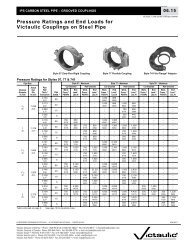
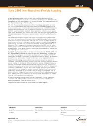
EXPANSION COUPLING<strong>Style</strong> <strong>231S</strong> <strong>Non</strong>-<strong>Restrained</strong> <strong>Flexible</strong><strong>Expansion</strong> <strong>Coupling</strong>60.04RESTRAINT RINGSdZLCd L 1Type 1 - Restraint Ring LocationZLCd L 1L 2dType 2 - Restraint Ring LocationdESdS(E)Pipe EndRestraint Ring Single FlareBevel Groove Weld DetailType 1S(E)EEPipe EndSSRestraint Ring Single Flare Bevel Groove Weld DetailType 2NominalPipeSizeIn./mm481200541350601500661650721800(1)MaximumWorkingPressurepsi/kPa5034520013752517017512002517015010351501035125860Body Type22222222Width(Z)In./mm14.38Diameter(d)In./mmRestraint RingsLocation(L1)In./mm(3) (3)Location(L2)In./mm1/44.50 6.38365.1 114.3 161.916.381/44.50 6.38415.9 114.3 161.918.381/44.50 6.38466.7 114.3 161.914.381/44.50 6.38365.1 114.3 161.916.381/44.50 6.38415.9 114.3 161.918.381/44.50 6.38466.7 114.3 161.914.381/44.50 6.50365.1 114.3 165.116.381/44.50 6.50415.9 114.3 165.118.381/44.50 6.50466.7 114.3 165.114.381/44.50 6.50365.1 114.3 165.116.381/44.50 6.50415.9 114.3 165.118.381/44.50 6.50466.7 114.3 165.114.381/44.50 6.50365.1 114.3 165.116.381/44.50 6.50415.9 114.3 165.118.381/44.50 6.50466.7 114.3 165.114.381/44.50 6.50365.1 114.3 165.116.381/44.50 6.50415.9 114.3 165.118.381/44.50 6.50466.7 114.3 165.114.381/44.50 6.50365.1 114.3 165.116.381/44.50 6.50415.9 114.3 165.118.381/44.50 6.50466.7 114.3 165.114.381/44.50 6.50365.1 114.3 165.116.381/44.50 6.50415.9 114.3 165.118.381/44.50 6.50466.7 114.3 165.1Weld Size(E)In.(1) For allowable test or transient pressure, the maximum working pressure may be increased to 11/2 times the values shown.(2) Restraint rings must be welded perpendicular to the pipe axis with a tolerance of L± 1/16"/1.6 mm. Each restraintring shipment includes restraint ring placement and welding data that is specific to application or project requirements.Contact <strong>Victaulic</strong> for details.(3) Flare bevel groove weld size in table is the minimum requirement. Depth of preparation S = (d) ÷ 2; Weld sizeE ≈ S * 0.625 per AWS D1.1. The coupling shoulder must have unrestricted contact with the ring and the pipe O.D.3/323/323/323/323/323/323/323/323/323/323/323/323/323/323/323/323/323/323/323/323/323/323/323/32Note: The data in this table only applies when stainless steel couplings are being used on stainless steel pipe.www.victaulic.comVICTAULIC IS A REGISTERED TRADEMARK OF VICTAULIC COMPANY. © 2013 VICTAULIC COMPANY. ALL RIGHTS RESERVED.REV_J60.04_15