Style 231S Non-Restrained Flexible Expansion Coupling ... - Victaulic
Style 231S Non-Restrained Flexible Expansion Coupling ... - Victaulic
Style 231S Non-Restrained Flexible Expansion Coupling ... - Victaulic

Create successful ePaper yourself
Turn your PDF publications into a flip-book with our unique Google optimized e-Paper software.
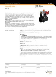
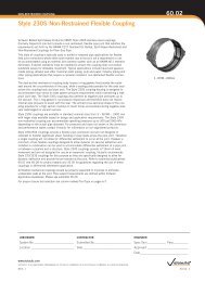
EXPANSION COUPLING60.04<strong>Style</strong> <strong>231S</strong> <strong>Non</strong>-<strong>Restrained</strong> <strong>Flexible</strong><strong>Expansion</strong> <strong>Coupling</strong>COUPLING COMPONENTS1. Body – Dual arch cross-section.2. Shoulders (Type 2 only)Fixed Side – Rectangular steel bar located at coupling body edge provides additional stiffness,allows for larger o-ring gasket and provides vertical bearing surface for restraint ring.<strong>Expansion</strong> Side – Utilizes Teflon ® material to provide for a smooth sliding surface in order toaccommodate larger expansion values afforded by the <strong>Style</strong> <strong>231S</strong> Type 2 coupling.3. Closure Plates – Low profile bolt pads for installation and tightening of coupling; gap betweenplates of installed coupling allows for field flexibility.4. Sealing Plate – Provides axial seal across the coupling body and pipe joint.5. O-ring Gaskets – Provide circumferential seal.6. FastenersStuds – High Strength Threaded RodNuts – Heavy Hex NutsWashers – SAE small pattern flat washers7. Restraint Rings – Used to maintain coupling position on the "fixed" end of the pipe.15475126234673ONE SEGMENT HOUSINGTWO SEGMENT HOUSINGwww.victaulic.comVICTAULIC IS A REGISTERED TRADEMARK OF VICTAULIC COMPANY. © 2013 VICTAULIC COMPANY. ALL RIGHTS RESERVED.REV_J60.04_3
EXPANSION COUPLING<strong>Style</strong> <strong>231S</strong> <strong>Non</strong>-<strong>Restrained</strong> <strong>Flexible</strong><strong>Expansion</strong> <strong>Coupling</strong>60.04DIMENSIONSZ1-SEGMENTZ2-SEGMENT(1) (2) (3) <strong>Coupling</strong> Dimensions (4) (5) (6)NominaIPipeSizeIn./mm38041006150820010250123001435016400184502050024600ActualPipeO.D.RangeIn./mm2.88 - 3.5073.2 - 88.93.63 - 4.8892.2 - 123.95.00 - 6.88127.0-174.87.00 - 8.88177.8 - 225.69.00 - 10.8871.1 - 276.411.00 - 12.88279.4 - 327.213.00 - 14.88330.2 - 378.015.00 - 16.88381.0 - 428.817.00 - 18.88431.8 - 479.619.00 - 21.88482.6 - 555.822.00 - 26.88558.8 - 682.8MaximumWorkingPressurepsi/kPa300206530020653002065200137520013752001375200137520013753002065150103525017251501035250172510069015010353002065BodyThicknessIn.14 ga.14 ga.12 ga.11 ga.10 ga.10 ga.10 ga.3/161/41/41/43/161/41/41/43/161/41/41/43/161/41/41/43/83/83/8Width(Z)In./mm5.25Min. No. of<strong>Coupling</strong>SegmentsNo. of Fasteners -Fastener DimensionsDia. x LengthIn. x In.ApproximateWeightEachLbs/Kg.5.01 3 - 1/2 x 3 1/4133.4 2.35.251 3 - 1/2 x 3 1/45.0133.4 2.38.001 3 - 1/2 x 3 1/412.0203.2 5.410.001 3 - 5/8 x 521.0254.0 9.510.001 3 - 5/8 x 524.0254.0 10.910.001 3 - 5/8 x 528.0254.0 12.710.001 3 - 5/8 x 531.0254.0 14.110.001 3 - 3/4 x 648.0254.0 21.814.381 4 - 3/4 x 6102.0365.3 46.316.381 5 - 3/4 x 6115.0416.1 52.218.381 5 - 3/4 x 6125.0466.9 56.710.001 3 - 3/4 x 652.0254.0 23.614.381 4 - 3/4 x 6111.0365.3 50.316.381 5 - 3/4 x 6125.0416.1 56.718.381 5 - 3/4 x 6136.0466.9 61.710.001 3 - 3/4 x 656.0254.0 25.414.381 4 - 3/4 x 6120.0365.3 54.416.381 5 - 3/4 x 6135.0416.1 61.218.381 5 - 3/4 x 6147.0466.9 66.710.001 3 - 3/4 x 666.0254.0 29.914.381 4 - 3/4 x 6140.0365.3 63.516.381 5 - 3/4 x 6156.0416.1 70.818.381 5 - 3/4 x 6171.0466.9 77.614.382 8 - 7/8 x 8323.0365.3 146.516.382 10 - 7/8 x 8368.0416.1 166.918.382 10 - 7/8 x 8402.0466.9 182.3(1) <strong>Coupling</strong>s must be used on pipe with a minimum wall thickness that meets the requirements of AWWA C220 for stainless steel pipe.(2) For actual pipe O.D. round down to the nearest 1/8" to determine proper coupling size required.(3) For allowable test or transient pressure, the maximum working pressure may be increased to 11/2 times the values shown.(4) 1-segment couplings may be available as 2-segment couplings to allow for in-place pipe installations. Contact <strong>Victaulic</strong> for details.(5) <strong>Coupling</strong> weights are based on nominal pipe diameter and include all accessories. Weight may vary based on actual size of pipe.(6) Closure Tool Recommendations:*A= CTM-01 Small Manual Closure ToolB= CTM-02 Large Manual Closure ToolC= CTH-01 10-Ton Hydraulic Closure Tool*For more details on closure tools see page 17.Note: The data in this table only applies when stainless steel couplings are being used on stainless steel pipe.BodyTypeToolType1 A1 A1 A1 B,C1 B,C1 B,C1 B,C1 B,C2 C2 C2 C1 B,C2 C2 C2 C1 B,C2 C2 C2 C1 B,C2 C2 C2 C2 C2 C2 Cwww.victaulic.comVICTAULIC IS A REGISTERED TRADEMARK OF VICTAULIC COMPANY. © 2013 VICTAULIC COMPANY. ALL RIGHTS RESERVED.60.04_6REV_J
2010-07-30Euronext LisbonTM2010-07-30ACÇÕES (Continuação) (1)CBOLETIM DEOTAÇÕESMoedaValorNominal(Euros)QuantidadeadmitidaàNegociaçãoISIN /EuronextCodeCÓDIGOCENTRALSimb.Negoc.ICBGrupoNegoc.Cont. Comp.Fixing(2)DesignaçãoÚltima Cotação(3)E fectuadaEUR 0,01 309 096 828 PTZON0AM0006 ZON AM ZON 5553 P0 C A ZON MULTIMEDIA 2010/07/29 3,179 3,233 3,233 3,2039 3,185 3,185 3,182 3,198 354 517EstrangeirasEUR 0,50 8 228 826 135 NSCPT000BSC8 KBS AM SANT 8355 P5 C B.Santander 2010/07/29 10,34 10,29 10,29 10,0633 9,95 10,04 10,03 10,10 82 074EUR 0,10 1 333 151 690 ES0113790531 KBP AM BPE 8355 P5 C Banco Popular Español 2010/07/28 5,34 5,07 5,07 5,07 5,07 5,07 5,05 5,34 1 500EUR 10,00 45 223 707 LU0011904405 KES AE ESF 8775 P5 C E. Santo Financial Group 2010/07/29 14,05 14,00 14,08 14,0342 14,00 14,08 14,00 14,08 1 404EUR 10,00 32 631 209 LU0202957089 KES AM ESFN 8775 P6 F E. Santo Financial Group - Nom. 2010/07/07 13,90EUR 5,00 872 308 162 ES0127797019 KER AM EDPR 7537 P0 C EDP Renováveis 2010/07/29 4,622 4,659 4,67 4,5814 4,55 4,583 4,583 4,60 1 120 375EUR 1,00 304 967 371 ES0182870214 KSV AE SYVA 2357 P6 F Sacyr Vallehermoso 2009/05/06 7,95DataPreço(Euros)Abert.MáximoPreço( Eu ros)MédioMínimoFechoCompraOferta(Euros)VendaQuantidadeEfectuadaEXCHANGE TRADED FUNDS (1)ValorNominal(Euros)ISIN /EuronextCodeCÓDIGOCENTRALSimb.Negoc.GrupoNegoc.Cont.FixingDesignaçãoUnidade de ParticipaçãoDataValorQuantidadeadmitidaÚltima Cotação(3)E fectuadaDataPreço(Euros)Abert.MáximoPreço( Eu ros)MédioMínimoFechoCompraOferta(Euros)VendaQuantidadeEfectuadaDIREITOS OS E WARRANTS DESTACADOS (1)Valores asubscreverPreço desubscriçãounitário(u.m.)Data Fim doExercício deDireitosISIN /EuronextCodeCÓDIGOCENTRALSímbolo GrupoNegociação NegociaçãoContínuoFixingDesignaçãoÚltima CotaçãoEfectuadaDataPreço(Euros)Abert.MáximoPreço( Eu ros)MédioMínimoFechoCompraOferta(Euros)VendaQuantidadeEfectuadaEuronext Lisbon - Sociedade Gestora de Mercados Regulamentados, SA - 7 -
EXPANSION COUPLING<strong>Style</strong> <strong>231S</strong> <strong>Non</strong>-<strong>Restrained</strong> <strong>Flexible</strong><strong>Expansion</strong> <strong>Coupling</strong>60.04DIMENSIONSZ1-SEGMENTZ2-SEGMENT(1) (2) (3) <strong>Coupling</strong> Dimensions (4) (5) (6)NominaIPipeSizeIn./mm541350601500661650721800781950842100902250ActualPipeRangeIn./mm51.00 - 56.881295.4 - 1444.857.00 - 62.881447.8 - 1597.263.00 - 68.881600.2 - 1749.669.00 - 74.881752.6 - 1902.075.00 - 80.881905.0 - 2054.481.00 - 86.882057.4 - 2206.887.00 - 92.882209.8 - 2359.2MaximumWorkingPressurepsi/kPa2517017512002517015010351501035125860125860100690100690BodyThicknessIn.1/41/41/43/83/83/81/41/41/43/83/83/83/83/83/83/83/83/83/83/83/83/83/83/83/83/83/8Width(Z)In./mm14.38Min. No. of<strong>Coupling</strong>SegmentsNo. of Fasteners -Fastener DimensionsDia. x LengthIn. x In.ApproximateWeightEachLbs/Kg.306.01 4 - 7/8 x 8365.3 138.816.381 5 - 7/8 x 8341.0416.1 154.718.381 5 - 7/8 x 8371.0466.9 168.314.382 8 - 7/8 x 8563.0365.3 255.416.382 10 - 7/8 x 8638.0416.1 289.418.382 10 - 7/8 x 8702.0466.9 318.414.382 8 - 7/8 x 8390.0365.3 176.916.382 10 - 7/8 x 8438.0416.1 198.718.382 10 - 7/8 x 8476.0466.9 215.914.382 8 - 7/8 x 8615.0365.3 279.016.382 10 - 7/8 x 8696.0416.1 315.718.382 10 - 7/8 x 8765.0466.9 346.914.382 8 - 7/8 x 8652.0365.3 295.716.382 10 - 7/8 x 8739.0416.1 335.218.382 10 - 7/8 x 8812.0466.9 368.314.382 8 - 7/8 x 8703.0365.3 318.916.382 10 - 7/8 x 8795.0416.1 360.618.382 10 - 7/8 x 8875.0466.9 396.814.382 8 - 7/8 x 8742.0365.3 336.616.382 10 - 7/8 x 8838.0416.1 380.118.382 10 - 7/8 x 8922.0466.9 418.214.382 8 - 7/8 x 8792.0365.3 359.216.382 10 - 7/8 x 8911.0416.1 413.218.382 10 - 7/8 x 81001.0466.9 454.014.382 8 - 7/8 x 8830.0365.3 376.516.382 10 - 7/8 x 8937.0416.1 425.018.382 10 - 7/8 x 81032.0466.9 468.1(1) <strong>Coupling</strong>s must be used on pipe with a minimum wall thickness that meets the requirements of AWWA C220 for stainless steel pipe.(2) For actual pipe O.D. round down to the nearest 1/8" to determine proper coupling size required.(3) For allowable test or transient pressure, the maximum working pressure may be increased to 11/2 times the values shown.(4) 1-segment couplings may be available as 2-segment couplings to allow for in-place pipe installations. Contact <strong>Victaulic</strong> for details.(5) <strong>Coupling</strong> weights are based on nominal pipe diameter and include all accessories. Weight may vary based on actual size of pipe.(6) Closure Tool Recommendations:*A= CTM-01 Small Manual Closure Tool B= CTM-02 Large Manual Closure Tool C= CTH-01 10-Ton Hydraulic Closure Tool*For more details on closure tools see page 17.Note: The data in this table only applies when stainless steel couplings are being used on stainless steel pipe.BodyTypeToolType2 C2 C2 C2 C2 C2 C2 C2 C2 C2 C2 C2 C2 C2 C2 C2 C2 C2 C2 C2 C2 C2 C2 C2 C2 C2 C2 Cwww.victaulic.comVICTAULIC IS A REGISTERED TRADEMARK OF VICTAULIC COMPANY. © 2013 VICTAULIC COMPANY. ALL RIGHTS RESERVED.60.04_8REV_J
EXPANSION COUPLING<strong>Style</strong> <strong>231S</strong> <strong>Non</strong>-<strong>Restrained</strong> <strong>Flexible</strong><strong>Expansion</strong> <strong>Coupling</strong>60.04DIMENSIONSZ(1) (2) (3) <strong>Coupling</strong> Dimensions (4) (5) (6)NominaIPipeSizeIn./mm962400ActualPipeO.D.RangeIn./mm93.00 - 102.002362.2 - 2590.8MaximumWorkingPressurepsi/kPa100690BodyThicknessIn.3/83/83/8Width(Z)In./mm14.38Min. No. of<strong>Coupling</strong>SegmentsNo. of Fasteners -Fastener DimensionsDia. x LengthIn. x In.ApproximateWeightEachLbs/Kg.893.02 8 - 7/8 x 8365.3 405.116.382 10 - 7/8 x 81008.0416.1 457.218.382 10 - 7/8 x 81111.0466.9 503.9(1) <strong>Coupling</strong>s must be used on pipe with a minimum wall thickness that meets the requirements of AWWA C220 for stainless steel pipe.(2) For actual pipe O.D. round down to the nearest 1/8" to determine proper coupling size required.(3) For allowable test or transient pressure, the maximum working pressure may be increased to 11/2 times the values shown.(4) 1-segment couplings may be available as 2-segment couplings to allow for in-place pipe installations. Contact <strong>Victaulic</strong> for details.(5) <strong>Coupling</strong> weights are based on nominal pipe diameter and include all accessories. Weight may vary based on actual size of pipe.(6) Closure Tool Recommendations:*A= CTM-01 Small Manual Closure ToolB= CTM-02 Large Manual Closure ToolC= CTH-01 10-Ton Hydraulic Closure Tool*For more details on closure tools see page 17.Note: The data in this table only applies when stainless steel couplings are being used on stainless steel pipe.BodyTypeToolType2 C2 C2 C1-SEGMENTZ2-SEGMENTwww.victaulic.comVICTAULIC IS A REGISTERED TRADEMARK OF VICTAULIC COMPANY. © 2013 VICTAULIC COMPANY. ALL RIGHTS RESERVED.REV_J60.04_9
EXPANSION COUPLING60.04<strong>Style</strong> <strong>231S</strong> <strong>Non</strong>-<strong>Restrained</strong> <strong>Flexible</strong><strong>Expansion</strong> <strong>Coupling</strong>PERFORMANCENominalPipeSizeIn./mm38041006150820010250123001435016400184502050024600MaximumWorkingPressurepsi/kPaCarbon Steel300206530020653002065200137520013752001375200137520013753002065150103525017251501035250172510069015010353002065(1) (2)MaximumWorkingPressurepsi/kPaStainless Steel300206530020653002065200137520013752001375200137520013753002065150103525017251501035250172510069015010353002065MaximumWorkingPressurepsi/kPaDuctile IronBody TypeN/R 1N/R 1N/R 1N/R 1N/R 1N/R 1N/R 1N/R 1N/R222N/R 1N/R222N/R 1N/R222N/R 1N/RN/R222222Width(Z)In./mm5.25133.45.25133.48.00203.210.00254.010.00254.010.00254.010.00254.0Pipe EndSeparationMin - MaxIn./mm0 - 0.750 - 19.10 - 0.750 - 19.10 -1.250 -31.80 -1.500 - 38.10 -1.500 - 38.10 -1.500 - 38.10 -1.500 - 38.1Max.AllowableAxial PipeMovementIn./mm0.7519.10.7519.11.2531.81.538.11.538.11.538.11.538.110.00 0 -1.50 1.5254.0 0 - 38.1 38.114.38 0 - 2.00 2.00365.3 0 - 50.8 50.816.38 0 - 3.00 3.00416.1 0 - 76.2 76.218.38 0 - 4.00 4.00466.9 0 - 101.6 101.610.00 0 -1.50 1.5254.0 0 - 38.1 38.114.38 0 - 2.00 2.00365.3 0 - 50.8 50.816.38 0 - 3.00 3.00416.1 0 - 76.2 76.218.38 0 - 4.00 4.00466.9 0 - 101.6 101.610.00 0 -1.50 1.5254.0 0 - 38.1 38.114.38 0 - 2.00 2.00365.3 0 - 50.8 50.816.38 0 - 3.00 3.00416.1 0 - 76.2 76.218.38 0 - 4.00 4.00466.9 0 - 101.6 101.610.00 0 -1.50 1.5254.0 0 - 38.1 38.114.38 0 - 2.00 2.00365.3 0 - 50.8 50.816.38 0 - 3.00 3.00416.1 0 - 76.2 76.218.38 0 - 4.00 4.00466.9 0 - 101.6 101.614.38 0 - 2.00 2.00365.3 0 - 50.8 50.816.38 0 - 3.00 3.00416.1 0 - 76.2 76.218.38 0 - 4.00 4.00466.9 0 - 101.6 101.6(1) For allowable test or transient pressure, the maximum working pressure may be increased to 1½ times the values shown.(2) The maximum pipe end separation in the tables also represents the maximum allowable axial pipe movement within the coupling. At maximum pipeend separation, axial pipe movement can only be accommodated in the direction of pipe expansion (pipe ends moving toward each other) withinthe coupled joint. At no time during operation should the pipe ends exceed the maximum listed values. The temperature of the pipe at time of installationwill impact the separation between pipe ends. Consult publication 26.20 or contact <strong>Victaulic</strong> for details.www.victaulic.comVICTAULIC IS A REGISTERED TRADEMARK OF VICTAULIC COMPANY. © 2013 VICTAULIC COMPANY. ALL RIGHTS RESERVED.60.04_10REV_J
EXPANSION COUPLING60.04<strong>Style</strong> <strong>231S</strong> <strong>Non</strong>-<strong>Restrained</strong> <strong>Flexible</strong><strong>Expansion</strong> <strong>Coupling</strong>PERFORMANCENominalPipeSizeIn./mm3075036900421050481200MaximumWorkingPressurepsi/kPaCarbon Steel1006903002065755152501725503452001375503452001375(1) (2)MaximumWorkingPressurepsi/kPaStainless Steel1006903002065755152501725503452001375503452001375MaximumWorkingPressurepsi/kPaDuctile IronN/RN/RN/RN/RN/RN/RN/RN/RBody Type222222222222222222222222Width(Z)In./mmPipe EndSeparationMin - MaxIn./mmMax.AllowableAxial PipeMovementIn./mm14.38 0 - 2.00 2.00365.3 0 - 50.8 50.816.38 0 - 3.00 3.00416.1 0 - 76.2 76.218.38 0 - 4.00 4.00466.9 0 - 101.6 101.614.38 0 - 2.00 2.00365.3 0 - 50.8 50.816.38 0 - 3.00 3.00416.1 0 - 76.2 76.218.38 0 - 4.00 4.00466.9 0 - 101.6 101.614.38 0 - 2.00 2.00365.3 0 - 50.8 50.816.38 0 - 3.00 3.00416.1 0 - 76.2 76.218.38 0 - 4.00 4.00466.9 0 - 101.6 101.614.38 0 - 2.00 2.00365.3 0 - 50.8 50.816.38 0 - 3.00 3.00416.1 0 - 76.2 76.218.38 0 - 4.00 4.00466.9 0 - 101.6 101.614.38 0 - 2.00 2.00365.3 0 - 50.8 50.816.38 0 - 3.00 3.00416.1 0 - 76.2 76.218.38 0 - 4.00 4.00466.9 0 - 101.6 101.614.38 0 - 2.00 2.00365.3 0 - 50.8 50.816.38 0 - 3.00 3.00416.1 0 - 76.2 76.218.38 0 - 4.00 4.00466.9 0 - 101.6 101.614.38 0 - 2.00 2.00365.3 0 - 50.8 50.816.38 0 - 3.00 3.00416.1 0 - 76.2 76.218.38 0 - 4.00 4.00466.9 0 - 101.6 101.614.38 0 - 2.00 2.00365.3 0 - 50.8 50.816.38 0 - 3.00 3.00416.1 0 - 76.2 76.218.38 0 - 4.00 4.00466.9 0 - 101.6 101.6(1) For allowable test or transient pressure, the maximum working pressure may be increased to 1½ times the values shown.(2) The maximum pipe end separation in the tables also represents the maximum allowable axial pipe movement within the coupling. At maximum pipeend separation, axial pipe movement can only be accommodated in the direction of pipe expansion (pipe ends moving toward each other) withinthe coupled joint. At no time during operation should the pipe ends exceed the maximum listed values. The temperature of the pipe at time of installationwill impact the separation between pipe ends. Consult publication 26.20 or contact <strong>Victaulic</strong> for details.www.victaulic.comVICTAULIC IS A REGISTERED TRADEMARK OF VICTAULIC COMPANY. © 2013 VICTAULIC COMPANY. ALL RIGHTS RESERVED.REV_J60.04_11
EXPANSION COUPLING<strong>Style</strong> <strong>231S</strong> <strong>Non</strong>-<strong>Restrained</strong> <strong>Flexible</strong><strong>Expansion</strong> <strong>Coupling</strong>60.04PERFORMANCENominalPipeSizeIn./mm541350601500661650721800781950842100902250962400MaximumWorkingPressurepsi/kPaCarbon Steel2517017512002517015010351501035125860125860100690100690100690(1) (2)MaximumWorkingPressurepsi/kPaStainless Steel2517017512002517015010351501035125860125860100690100690100690MaximumWorkingPressurepsi/kPaDuctile IronN/RN/RN/RN/RN/RN/RN/RN/RN/RN/RBody Type222222222222222222222222222222Width(Z)In./mmPipe EndSeparationMin - MaxIn./mmMax. AllowableAxial PipeMovementIn./mm14.38 0 - 2.00 2.00365.3 0 - 50.8 50.816.38 0 - 3.00 3.00416.1 0 - 76.2 76.218.38 0 - 4.00 4.00466.9 0 - 101.6 101.614.38 0 - 2.00 2.00365.3 0 - 50.8 50.816.38 0 - 3.00 3.00416.1 0 - 76.2 76.218.38 0 - 4.00 4.00466.9 0 - 101.6 101.614.38 0 - 2.00 2.00365.3 0 - 50.8 50.816.38 0 - 3.00 3.00416.1 0 - 76.2 76.218.38 0 - 4.00 4.00466.9 0 - 101.6 101.614.38 0 - 2.00 2.00365.3 0 - 50.8 50.816.38 0 - 3.00 3.00416.1 0 - 76.2 76.218.38 0 - 4.00 4.00466.9 0 - 101.6 101.614.38 0 - 2.00 2.00365.3 0 - 50.8 50.816.38 0 - 3.00 3.00416.1 0 - 76.2 76.218.38 0 - 4.00 4.00466.9 0 - 101.6 101.614.38 0 - 2.00 2.00365.3 0 - 50.8 50.816.38 0 - 3.00 3.00416.1 0 - 76.2 76.218.38 0 - 4.00 4.00466.9 0 - 101.6 101.614.38 0 - 2.00 2.00365.3 0 - 50.8 50.816.38 0 - 3.00 3.00416.1 0 - 76.2 76.218.38 0 - 4.00 4.00466.9 0 - 101.6 101.614.38 0 - 2.00 2.00365.3 0 - 50.8 50.816.38 0 - 3.00 3.00416.1 0 - 76.2 76.218.38 0 - 4.00 4.00466.9 0 - 101.6 101.614.38 0 - 2.00 2.00365.3 0 - 50.8 50.816.38 0 - 3.00 3.00416.1 0 - 76.2 76.218.38 0 - 4.00 4.00466.9 0 - 101.6 101.614.38 0 - 2.00 2.00365.3 0 - 50.8 50.816.38 0 - 3.00 3.00416.1 0 - 76.2 76.218.38 0 - 4.00 4.00466.9 0 - 101.6 101.6(1) For allowable test or transient pressure, the maximum working pressure may be increased to 1½ times the values shown.(2) The maximum pipe end separation in the tables also represents the maximum allowable axial pipe movement within the coupling. At maximum pipeend separation, axial pipe movement can only be accommodated in the direction of pipe expansion (pipe ends moving toward each other) withinthe coupled joint. At no time during operation should the pipe ends exceed the maximum listed values. The temperature of the pipe at time of installationwill impact the separation between pipe ends. Consult publication 26.20 or contact <strong>Victaulic</strong> for details.www.victaulic.comVICTAULIC IS A REGISTERED TRADEMARK OF VICTAULIC COMPANY. © 2013 VICTAULIC COMPANY. ALL RIGHTS RESERVED.60.04_12REV_J
EXPANSION COUPLING<strong>Style</strong> <strong>231S</strong> <strong>Non</strong>-<strong>Restrained</strong> <strong>Flexible</strong><strong>Expansion</strong> <strong>Coupling</strong>60.04RESTRAINT RINGSdZLCd L 1Type 1 - Restraint Ring LocationZLCd L 1L 2dType 2 - Restraint Ring LocationdESdS(E)Pipe EndRestraint Ring Single FlareBevel Groove Weld DetailType 1S(E)EEPipe EndSSRestraint Ring Single Flare Bevel Groove Weld DetailType 2NominalPipeSizeIn./mm380410061508200102501235014350164001845020500(1)MaximumWorkingPressurepsi/kPa3002065300206530020652001375200137520013752001375200137530020651501035300206515010353002065Body Type1111111121212Width(Z)In./mm5.25Diameter(d)In./mmRestraint RingsLocation(L1)In./mm(3) (3)Location(L2)In./mm1/81.25 –133.4 31.8 –5.253/161.13 –133.4 28.6 –8.003/161.75 –203.2 44.5 –10.001/42.00 –254.0 50.8 –10.001/42.00 –254.0 50.8 –10.001/42.00 –254.0 50.8 –10.001/42.00 –254.0 50.8 –10.001/42.00 –254.0 50.8 –14.381/44.50 6.25365.3 114.3 158.816.381/44.50 6.25416.1 114.3 158.818.381/44.50 6.25466.9 114.3 158.810.001/42.00 –254.0 50.8 –14.381/44.50 6.25365.3 114.3 158.816.381/44.50 6.25416.1 114.3 158.818.381/44.50 6.25466.9 114.3 158.810.001/42.00 –254.0 50.8 –14.381/44.50 6.25365.3 114.3 158.816.381/44.50 6.25416.1 114.3 158.818.381/44.50 6.25466.9 114.3 158.8Weld Size(E)In.(1) For allowable test or transient pressure, the maximum working pressure may be increased to 11/2 times the values shown.(2) Restraint rings must be welded perpendicular to the pipe axis with a tolerance of L± 1/16"/1.6 mm. Each restraintring shipment includes restraint ring placement and welding data that is specific to application or project requirements.Contact <strong>Victaulic</strong> for details.(3) Flare bevel groove weld size in table is the minimum requirement. Depth of preparation S = (d) ÷ 2; Weld sizeE ≈ S * 0.625 per AWS D1.1. The coupling shoulder must have unrestricted contact with the ring and the pipe O.D.1/161/161/163/323/323/323/323/323/323/323/323/323/323/323/323/323/323/323/32Note: The data in this table only applies when stainless steel couplings are being used on stainless steel pipe.www.victaulic.comVICTAULIC IS A REGISTERED TRADEMARK OF VICTAULIC COMPANY. © 2013 VICTAULIC COMPANY. ALL RIGHTS RESERVED.REV_J60.04_13
EXPANSION COUPLING<strong>Style</strong> <strong>231S</strong> <strong>Non</strong>-<strong>Restrained</strong> <strong>Flexible</strong><strong>Expansion</strong> <strong>Coupling</strong>60.04RESTRAINT RINGSdZLCd L 1Type 1 - Restraint Ring LocationZLCd L 1L 2dType 2 - Restraint Ring LocationdESdS(E)Pipe EndRestraint Ring Single FlareBevel Groove Weld DetailType 1S(E)EEPipe EndSSRestraint Ring Single Flare Bevel Groove Weld DetailType 2NominalPipeSizeIn./mm246003075036900421050(1)MaximumWorkingPressurepsi/kPa100690150103530020651006903002065755152501725503452001375Body Type122222222Width(Z)In./mm10.00Diameter(d)In./mmRestraint RingsLocation(L1)In./mm(3) (3)Location(L2)In./mm1/42.00 –254.0 50.8 –14.381/44.50 6.25365.3 114.3 158.816.381/44.50 6.25416.1 114.3 158.818.381/44.50 6.25466.9 114.3 158.814.381/44.50 6.25365.3 114.3 158.816.381/44.50 6.25416.1 114.3 158.818.381/44.50 6.25466.9 114.3 158.814.381/44.50 6.25365.3 114.3 158.816.381/44.50 6.25416.1 114.3 158.818.381/44.50 6.25466.9 114.3 158.814.381/44.50 6.25365.3 114.3 158.816.381/44.50 6.25416.1 114.3 158.818.381/44.50 6.25466.9 114.3 158.814.381/44.50 6.38365.3 114.3 161.916.381/44.50 6.38416.1 114.3 161.918.381/44.50 6.38466.9 114.3 161.914.381/44.50 6.38365.3 114.3 161.916.381/44.50 6.38416.1 114.3 161.918.381/44.50 6.38466.9 114.3 161.914.381/44.50 6.38365.3 114.3 161.916.381/44.50 6.38416.1 114.3 161.918.381/44.50 6.38466.9 114.3 161.914.381/44.50 6.38365.3 114.3 161.916.381/44.50 6.38416.1 114.3 161.918.381/44.50 6.38466.9 114.3 161.9Weld Size(E)In.(1) For allowable test or transient pressure, the maximum working pressure may be increased to 11/2 times the values shown.(2) Restraint rings must be welded perpendicular to the pipe axis with a tolerance of L± 1/16"/1.6 mm. Each restraintring shipment includes restraint ring placement and welding data that is specific to application or project requirements.Contact <strong>Victaulic</strong> for details.(3) Flare bevel groove weld size in table is the minimum requirement. Depth of preparation S = (d) ÷ 2; Weld sizeE ≈ S * 0.625 per AWS D1.1. The coupling shoulder must have unrestricted contact with the ring and the pipe O.D.3/323/323/323/323/323/323/323/323/323/323/323/323/323/323/323/323/323/323/323/323/323/323/323/323/32Note: The data in this table only applies when stainless steel couplings are being used on stainless steel pipe.www.victaulic.comVICTAULIC IS A REGISTERED TRADEMARK OF VICTAULIC COMPANY. © 2013 VICTAULIC COMPANY. ALL RIGHTS RESERVED.60.04_14REV_J
EXPANSION COUPLING<strong>Style</strong> <strong>231S</strong> <strong>Non</strong>-<strong>Restrained</strong> <strong>Flexible</strong><strong>Expansion</strong> <strong>Coupling</strong>60.04RESTRAINT RINGSdZLCd L 1Type 1 - Restraint Ring LocationZLCd L 1L 2dType 2 - Restraint Ring LocationdESdS(E)Pipe EndRestraint Ring Single FlareBevel Groove Weld DetailType 1S(E)EEPipe EndSSRestraint Ring Single Flare Bevel Groove Weld DetailType 2NominalPipeSizeIn./mm481200541350601500661650721800(1)MaximumWorkingPressurepsi/kPa5034520013752517017512002517015010351501035125860Body Type22222222Width(Z)In./mm14.38Diameter(d)In./mmRestraint RingsLocation(L1)In./mm(3) (3)Location(L2)In./mm1/44.50 6.38365.1 114.3 161.916.381/44.50 6.38415.9 114.3 161.918.381/44.50 6.38466.7 114.3 161.914.381/44.50 6.38365.1 114.3 161.916.381/44.50 6.38415.9 114.3 161.918.381/44.50 6.38466.7 114.3 161.914.381/44.50 6.50365.1 114.3 165.116.381/44.50 6.50415.9 114.3 165.118.381/44.50 6.50466.7 114.3 165.114.381/44.50 6.50365.1 114.3 165.116.381/44.50 6.50415.9 114.3 165.118.381/44.50 6.50466.7 114.3 165.114.381/44.50 6.50365.1 114.3 165.116.381/44.50 6.50415.9 114.3 165.118.381/44.50 6.50466.7 114.3 165.114.381/44.50 6.50365.1 114.3 165.116.381/44.50 6.50415.9 114.3 165.118.381/44.50 6.50466.7 114.3 165.114.381/44.50 6.50365.1 114.3 165.116.381/44.50 6.50415.9 114.3 165.118.381/44.50 6.50466.7 114.3 165.114.381/44.50 6.50365.1 114.3 165.116.381/44.50 6.50415.9 114.3 165.118.381/44.50 6.50466.7 114.3 165.1Weld Size(E)In.(1) For allowable test or transient pressure, the maximum working pressure may be increased to 11/2 times the values shown.(2) Restraint rings must be welded perpendicular to the pipe axis with a tolerance of L± 1/16"/1.6 mm. Each restraintring shipment includes restraint ring placement and welding data that is specific to application or project requirements.Contact <strong>Victaulic</strong> for details.(3) Flare bevel groove weld size in table is the minimum requirement. Depth of preparation S = (d) ÷ 2; Weld sizeE ≈ S * 0.625 per AWS D1.1. The coupling shoulder must have unrestricted contact with the ring and the pipe O.D.3/323/323/323/323/323/323/323/323/323/323/323/323/323/323/323/323/323/323/323/323/323/323/323/32Note: The data in this table only applies when stainless steel couplings are being used on stainless steel pipe.www.victaulic.comVICTAULIC IS A REGISTERED TRADEMARK OF VICTAULIC COMPANY. © 2013 VICTAULIC COMPANY. ALL RIGHTS RESERVED.REV_J60.04_15
EXPANSION COUPLING<strong>Style</strong> <strong>231S</strong> <strong>Non</strong>-<strong>Restrained</strong> <strong>Flexible</strong><strong>Expansion</strong> <strong>Coupling</strong>60.04RESTRAINT RINGSdZLCd L 1Type 1 - Restraint Ring LocationZLCd L 1L 2dType 2 - Restraint Ring LocationdESdS(E)Pipe EndRestraint Ring Single FlareBevel Groove Weld DetailType 1S(E)EEPipe EndSSRestraint Ring Single Flare Bevel Groove Weld DetailType 2NominalPipeSizeIn./mm781950842100902250962400(1)MaximumWorkingPressurepsi/kPa125860100690100690100690Body Type2222Width(Z)In./mm14.38Diameter(d)In./mmRestraint RingsLocation(L1)In./mm(3) (3)Location(L2)In./mm1/44.50 6.50365.3 114.3 165.116.381/44.50 6.50416.1 114.3 165.118.381/44.50 6.50466.9 114.3 165.114.381/44.50 6.50365.3 114.3 165.116.381/44.50 6.50416.1 114.3 165.118.381/44.50 6.50466.9 114.3 165.114.381/44.50 6.50365.3 114.3 165.116.381/44.50 6.50416.1 114.3 165.118.381/44.50 6.50466.9 114.3 165.114.381/44.50 6.50365.3 114.3 165.116.381/44.50 6.50416.1 114.3 165.118.381/44.50 6.50466.9 114.3 165.1Weld Size(E)In.(1) For allowable test or transient pressure, the maximum working pressure may be increased to 11/2 times the values shown.(2) Restraint rings must be welded perpendicular to the pipe axis with a tolerance of L± 1/16"/1.6 mm. Each restraintring shipment includes restraint ring placement and welding data that is specific to application or project requirements.Contact <strong>Victaulic</strong> for details.(3) Flare bevel groove weld size in table is the minimum requirement. Depth of preparation S = (d) ÷ 2; Weld sizeE ≈ S * 0.625 per AWS D1.1. The coupling shoulder must have unrestricted contact with the ring and the pipe O.D.Note: The data in this table only applies when stainless steel couplings are being used on stainless steel pipe.3/323/323/323/323/323/323/323/323/323/323/323/32www.victaulic.comVICTAULIC IS A REGISTERED TRADEMARK OF VICTAULIC COMPANY. © 2013 VICTAULIC COMPANY. ALL RIGHTS RESERVED.60.04_16REV_J
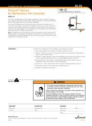
EXPANSION COUPLING60.04<strong>Style</strong> <strong>231S</strong> <strong>Non</strong>-<strong>Restrained</strong> <strong>Flexible</strong><strong>Expansion</strong> <strong>Coupling</strong>CLOSURE TOOLSMANUAL TOOLManual Tools• CTM-01: for use on 5" and 8" body widths• CTM-02: for use on 10" body widthsfor use on 12" body widths with thickness of 3/16" or lessHydraulic Tools• CTH-01*: for use on 12" body widths with thickness of 1/4" or greaterfor use on 14", 16" and 18" body widths• CTH-02: for use on all type 3 couplings• Hydraulic tool package comes standard with:• one (1) tool head• one (1) hydraulic cylinder• one (1) hydraulic hose• one (1) hand pump* A CTH-01 hydraulic closure tool can be used in applications where the CTM-02 manualclosure tool is recommended.Note: The closure tools listed above are designed specifically for <strong>Victaulic</strong> <strong>Style</strong> 230, 231,232 and 233 couplings. If ordering custom product, contact <strong>Victaulic</strong> for appropriate toolselection.HYDRAULIC TOOLwww.victaulic.comVICTAULIC IS A REGISTERED TRADEMARK OF VICTAULIC COMPANY. © 2013 VICTAULIC COMPANY. ALL RIGHTS RESERVED.REV_J60.04_17
EXPANSION COUPLING<strong>Style</strong> <strong>231S</strong> <strong>Non</strong>-<strong>Restrained</strong> <strong>Flexible</strong><strong>Expansion</strong> <strong>Coupling</strong>60.04PRODUCT CONFIGURATORC 0231 0096 50 X 2 C E 0 X X BActual Pipe O.D. * BodyPSI/kPa RubberClass <strong>Style</strong> Inches^ Fraction Type Segments Rating Compound PaintC 0231 0002through010200 – 013 – 1/825 – ¼38 – 3/850 – ½63 – 5/875 – ¾88 – 7/8X – Stainless 1 – One2 – TwoA – 25/170B – 50/345C – 75/515D – 100/690E – 125/860F – 150/1035G – 175/1200H – 200/1375J – 250/1725K – 300/2065E – EPDMI – IsopreneL – SiliconeT – NitrileV – NeopreneO – FluoroelastomerHardware0 – <strong>Non</strong>e X – Stainless X – StainlessRing onStainlessSteel PipeS – CarbonSteel Ring onCarbon SteelPipeD – CarbonSteel Ring onDuctile IronPipe^ <strong>Coupling</strong>s are available in a range of nominal sizes from 3 – 96".* For actual pipe O.D. round down to the nearest 1/8" to determine proper coupling size required.†Movement provided is dependent on size and body type and must correspond to allowable movements published in the product submittal.Ring PipeMaterial Movement †A – 0.75"B – 1.25"C – 1.50"D – 2.00"E – 3.00"F – 4.00"ENGINEERED PRODUCTSOPTIONSFor non-standard products the <strong>Victaulic</strong> Engineered Products group can assist with specialtyjoints designed to meet the specific size, pressure and temperature requirements of your system.WARRANTYRefer to the Warranty section of the current Price List or contact <strong>Victaulic</strong> for details.NOTEThis product shall be manufactured by <strong>Victaulic</strong> or to <strong>Victaulic</strong> specifications. All products to beinstalled in accordance with current <strong>Victaulic</strong> installation/assembly instructions. <strong>Victaulic</strong> reserves theright to change product specifications, designs and standard equipment without notice and withoutincurring obligations.TESTING<strong>Victaulic</strong> <strong>Style</strong> <strong>231S</strong> couplings are designed to allow for a 50 percent increase over the publishedmaximum working pressure for test and/or transient pressures. Due to the huge volume of air thatcan be involved in jobsite air testing and the nature of air or gas that is pressurized, jobsite air testingshould be limited to 25 psi/175 kPa or less.For complete contact information, visit www.victaulic.com60.04 3365 REV J UPDATED 08/2013VICTAULIC IS A REGISTERED TRADEMARK OF VICTAULIC COMPANY. © 2013 VICTAULIC COMPANY. ALL RIGHTS RESERVED.60.04