Schubert & Salzer 7036 Angle Seat Control Valve ... - RM Headlee
Schubert & Salzer 7036 Angle Seat Control Valve ... - RM Headlee
Schubert & Salzer 7036 Angle Seat Control Valve ... - RM Headlee

You also want an ePaper? Increase the reach of your titles
YUMPU automatically turns print PDFs into web optimized ePapers that Google loves.
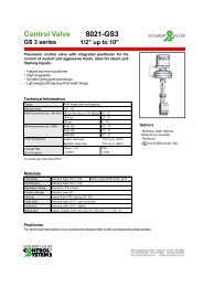
Flanged <strong>Control</strong> <strong>Valve</strong> <strong>7036</strong>1/2" up to 2"Pneumatically operated control valve with integrated positionerfor the control of neutral, slightly aggressive and highly aggressivemedia. Ideal for steam, gases and liquids.• Unaffected by lightly contaminated media• Body completely stainless steel• PTFE plug seal• ANSI class VI shutoff• Integrated positioner- pneumatic- electro-pneumatic- digital• Working pressure up to 580 psiPositionerInput signal range 0/4 - 20 mA, 0/2 - 10 V 0/4 - 20 mA, 0/2 - 10 V 0,2 - 1 barSupply voltage, electrical 24 V DC, maximum 10 W none noneSupply air pressure max. 87 psi max. 87 psi max. 87 psiHysteresis < 0,5 % < 1 % < 1 %Rangeability 30 :1 25 : 1 25 : 1CharacteristicsDigital positionerType 8048linear, equal percentage,user-defined, processoptimized*Characteristics of function unitCharacteristics of functionunitAdjustment (Stroke, zero point) self-adapting mechanical mechanicalAmbient temperature -4°F up to +167°F -4°F up to +140°F -4°F up to +176°FProtection class acc. DIN 40050 IP65 IP 54 IP 54Ex-proof (Optional) -i/p-positionerType 8047II 2 G EEx ib IIC T6 up to 113°FII 2 G EEx ib IIC T5 up to 140°Fp/p-positionerType 8047*Produces a linear process flow characteristic for optimal control. After entering a few process data points (e.g.upstream and downstream pressures) the optimised flow characteristic is calculated by the positioner configurationsoftware and stored in the positioner memory.-*90 psi supply air
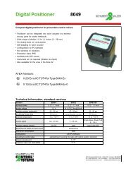
Flanged <strong>Control</strong> <strong>Valve</strong> <strong>7036</strong>with integrated positionerDigital Positioner Type 8049Version 4-wire 2-wire AS-ISet point signal 0/4 - 20 mA 4 - 20 mASingle Slave, Slave ProfilS - 7.3.4Burden voltage 1,2 V 14 V -Supply energy, electrical 24 VDC none supply with AS-IAdaption to range and zeroConfigurationself-calibratingwith PC-SoftwareAir capacity* to actuator 1.75 SCFM varies with design 1.75 SCFMSystem air consumptionnoneAmbient temperature limits -4 to +167°F -14 to +167°F -4 to+167°FSupply connectionClass of protectionNPT 1/8"IP 65* 90 psi supply airCv-ValueLinearEqual percentageDN 1/2" 3/4" 1" 1 1/4" 1 1/2" 2" 1/2" 3/4" 1" 1 1/4" 1 1/2" 2"100 % 4,4 10,2 16,2 23,2 31,3 42,9 3,5 7,0 11,6 18,6 29,0 -40 % 1,7 4,1 6,7 9,3 12,8 - 1,4 2,8 4,6 7,0 11,6 -25 % 1,1 2,6 4,2 - - - 0,9 1,7 3,0 - - -15% - - - - - - 0,5 - - - - -10% 0,5 - - - - - - - - - - -7,5% - - - - - - 0,3 - - - - -Admissible Pressuresdigital positionerp/p-positioner i/p-positionerDNPressure Supply pressurerangePistonØSpringconfigurationDNPressure Supply pressureRangePistonØSpringConfigurationpsi psi inch Number1/2" 235 60 - 90 3" 23/4" 235 60 - 90 3" 21" 235 60 - 90 3" 11 1/4" 145 60 - 90 3" 11 1/4" 235 45 - 90 5" 21 1/2" 85 60 - 90 3" 11 1/2" 235 60 - 90 5" 32" 45 60 - 90 3" 12" 130 60 - 90 5" 3psi psi inch Number1/2" 235 60 - 90 3" 23/4" 235 60 - 90 3" 21" 175 60 - 90 3" 11 1/4" 100 60 - 90 3" 11 1/4" 190 45 - 90 5" 21 1/2" 60 60 - 90 3" 11 1/2" 160 60 - 90 5" 32" 30 60 - 90 3" 12" 85 60 - 90 5" 3
Flanged <strong>Control</strong> <strong>Valve</strong> <strong>7036</strong>with integrated positionerOrdering Number System1 2 3 4 5 6 7 8 9 10 11 127 0 3 6 / V S 1 - 6 : Please quote all 6 sections7 - 12: Quote only if requiredSymbol: "V": <strong>Valve</strong>Model Size "A": Actuator (valve w ithout body)"R": Repair kit (sealings)1. Body type 2. Connection 3. Body4. <strong>Seat</strong> m aterials 5. Positioner 6. Actuator, Diam eter 7. Springsmaterials2 Flanged control C Flange acc. 2 Stainless steel 0 PTFE (Teflon) 6 p/p positioner Type 8047 1 Piston Ø 80 mm - Standardvalve ANSI #150 316 L 7 i/p positioner Type 8047 8 Piston 3" (NPT) springType <strong>7036</strong> 8 i/p positioner and w ith 2 Piston Ø 125 mm configurationplug connec. M12x1 Type 8047 9 Piston 5" (NPT) 1 spring to open9 as above, but for (only w ith dig.hazardous location usepositioner)(II 2 G EEx ib IIC T6)plug connec. M12x1 Type 8047A dig. positioner w ith processcontroller Type 8048 IPCC dig. positioner, Type8049, 4 w ireD dig. positioner Type 8048IP65 + pos. indicatorR dig. positioner, Type 8049,2 w ireT dig. positioner, Type 8049AS-i version8. Characteristic 9. Packing 10. Cv-value 11. Accessories 12. 13. Seal 14. Positionindicator- Linear - Standard - full Cv-value - w ithout S To state if some - Standard 0 With position1 red. to 40% stations are indicator1 Equal 2 Packing 2 red. to 25% quoted! (digitalpercentage underneath 3 red. to 15% positioner(vacuum) 4 red. to 7,5% standard)5 red. to 22,5%6 red. to 10%Ordering Example:<strong>7036</strong>/020V2C2067-1---S-0Flanged control valve with pneumatic positioner, nominal size 3/4", stainless steel body, PTFEsealing, 3" piston, equal percentage characteristic 100 %, with position indicator
10 07 550250y%1007550250Flanged <strong>Control</strong> <strong>Valve</strong> <strong>7036</strong>with integrated positionerDimensions and Weightsy%45°50°OAOBOCKFD45°OAOBOCKFD50°LLp/p-positionerType 8047i/p-positionerType 8047DN Actuator A B C D F F H K L* N Weight (lbs)p/p i/p stroke p/p i/p1/2" 3" 1.77 2.56 3.74 3.86 9.65 10.24 0.28 0.55 9.06 4 11.5 12.53/4" 3" 2.28 2.95 4.13 3.86 9.65 10.24 0.47 0.55 10.24 4 13.5 141" 3" 2.68 3.35 4.53 3.86 10.04 10.63 0.63 0.55 10.24 4 15 15.51 1/4" 3" 3.07 3.94 5.51 3.86 10.63 11.22 0.79 0.71 11.81 4 18.5 191 1/4" 5" 3.07 3.94 5.51 5.75 11.81 12.4 0.79 0.71 11.81 4 24 24.51 1/2" 3" 3.46 4.33 5.91 3.86 10.83 11.42 0.91 0.71 11.81 4 20 20.51 1/2" 5" 3.46 4.33 5.91 5.75 12.01 12.6 0.91 0.71 11.81 4 25.5 26.52" 3" 4.02 4.92 6.5 3.86 11.02 11.61 1.14 0.71 13.78 4 24.5 252" 5" 4.02 4.92 6.5 5.75 12.2 12.8 1.14 0.71 13.78 4 30 31*body dimension L acc. ASME B16.5Dimensions in inch
2550Flanged <strong>Control</strong> <strong>Valve</strong> <strong>7036</strong>with integrated positioner, Type 8048Dimensions and WeightsIO 3,4610075y%G1/8"0F45°SW 2D50°K1.4408ABCLEDN Actuator A B C D E F I SW2 K L* N Weight(lbs)Typ 80481/2" 3" 1.77 2.56 3.74 3.86 13.39 11.42 3.15 1.18 0.55 9.06 4 12.53/4" 3" 2.28 2.95 4.13 3.86 13.58 11.61 3.15 1.18 0.55 10.24 4 14.51" 3" 2.68 3.35 4.53 3.86 13.98 11.81 3.15 1.18 0.55 10.24 4 161 1/4" 3" 3.07 3.94 5.51 3.86 14.76 12.4 3.15 1.18 0.71 11.81 4 191 1/4" 4" 3.07 3.94 5.51 5.75 15.94 13.58 4.13 1.18 0.71 11.81 4 251 1/2" 3" 3.46 4.33 5.91 3.86 14.96 12.6 3.15 1.18 0.71 11.81 4 211 1/2" 4" 3.46 4.33 5.91 5.75 16.14 13.78 4.13 1.18 0.71 11.81 4 26.52" 3" 4.02 4.92 6.5 3.86 15.75 12.99 3.15 1.26 0.71 13.78 4 25.52" 4" 4.02 4.92 6.5 5.75 16.93 14.17 4.13 1.26 0.71 13.78 4 31*body dimension L acc. ASME B16.5Dimensions in inch
75100y%4,57Flanged <strong>Control</strong> <strong>Valve</strong> <strong>7036</strong>with integrated positioner, Type 8049Dimensions and WeightsG1/8"I5025F045°DSW 250°K1.4408ISOBACLEText and pictures are not binding. We reserve the right, to alter the equipment.DN Actuator A B C D E F I SW2 K L* N Weight(kg)Typ 80491/2" 3" 1.77 2.56 3.74 3.86 12.99 11.89 3.15 1.18 0.55 9.06 4 133/4" 3" 2.28 2.95 4.13 3.86 13.19 12.09 3.15 1.18 0.55 10.24 4 151" 3" 2.68 3.35 4.53 3.86 13.58 12.28 3.15 1.18 0.55 10.24 4 16.51 1/4" 3" 3.07 3.94 5.51 3.86 14.37 12.87 3.15 1.18 0.71 11.81 4 191 1/4" 4" 3.07 3.94 5.51 5.75 15.55 14.06 4.13 1.18 0.71 11.81 4 25.51 1/2" 3" 3.46 4.33 5.91 3.86 14.57 13.07 3.15 1.18 0.71 11.81 4 21.51 1/2" 4" 3.46 4.33 5.91 5.75 15.75 14.25 4.13 1.18 0.71 11.81 4 27.52" 3" 4.02 4.92 6.5 3.86 15.35 13.46 3.15 1.26 0.71 13.78 4 262" 4" 4.02 4.92 6.5 5.75 16.54 14.65 4.13 1.26 0.71 13.78 4 31.5*body dimension L acc. ASME 16.5Dimensions in inchData sheet <strong>7036</strong>usa /Version: 07-17-2007