872-13-03-008 peri-loc 4.5 lateral proximal tibia locking targeter ...
872-13-03-008 peri-loc 4.5 lateral proximal tibia locking targeter ...
872-13-03-008 peri-loc 4.5 lateral proximal tibia locking targeter ...
- No tags were found...

You also want an ePaper? Increase the reach of your titles
YUMPU automatically turns print PDFs into web optimized ePapers that Google loves.
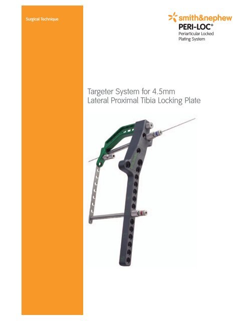
Surgical TechniqueTargeter System for <strong>4.5</strong>mmLateral Proximal Tibia Locking Plate
PERI-LOC PeriarticularLocked Plating SystemTargeter System for <strong>4.5</strong>mmLateral Proximal Tibia Locking PlateContentsProduct Overview ............................................................................2Indications........................................................................................2Design Features – <strong>4.5</strong>mm Lateral Proximal Tibia Locking Plate......3Design Features – Targeter..............................................................4Patient Positioning ..........................................................................5Incision ............................................................................................5<strong>4.5</strong>mm Lateral Proximal Tibia Locking Plate Surgical TechniquePlate Selection ..........................................................................6Articular Reduction and Provisional Fixation ............................7Plate and Targeter Assembly ....................................................7Plate Insertion ..........................................................................8Plate Positioning........................................................................8Screw Insertion ........................................................................12Catalog Information ........................................................................17Nota BeneThe technique description herein is made available to the healthcare professional toillustrate the author's suggested treatment for the uncomplicated procedure. In the finalanalysis, the preferred treatment is that which addresses the needs of the specific patient.
Product OverviewThe PERI-LOC Periarticular Locked Plating System from Smith &Nephew offers the advantages of <strong>loc</strong>ked plating with the flexibilityand benefits of traditional plating in one system. Utilizing both <strong>loc</strong>kingand non-<strong>loc</strong>king screws, PERI-LOC offers a construct that resistsangular (e.g. varus/valgus) collapse while simultaneously acting as aneffective aid to fracture reduction. A simple and straightforwardinstrument set features one screwdriver, standardized drill bits, andcolor-coded instrumentation, making PERI-LOC efficient and easyto use.All PERI-LOC implants are manufactured using the highest quality 316Lstainless steel for strength and durability.The precontour of the <strong>4.5</strong>mm Proximal Tibia Locking Plate provides anexcellent fit against the surface of the bone.Scallops at the <strong>proximal</strong> end of the plate allow easy placement of lagscrews outside the plate for fixation of articular fractures.Each screw hole in the <strong>4.5</strong>mm Lateral Proximal Tibia Locking Plate willaccept one of four different screws allowing customization of thescrew configuration depending on the individual needs of thefracture:• <strong>4.5</strong>mm Self-Tapping Cortex Screw (Non-Locking)• <strong>4.5</strong>mm Locking Self-Tapping Cortex Screw• 5.7mm Cannulated Locking Screw• 6.5mm Partially Threaded Cancellous ScrewIndicationsThe PERI-LOC Periarticular Locked Plating System can be used in adultand pediatric patients as well as patients with osteopenic bone. It isindicated for fixation of pelvic, small and long bone fractures, includingthose of the <strong>tibia</strong>, fibula, femur, pelvis, acetabulum, metacarpals,metatarsals, humerus, ulna, and calcaneus.Disposable components in the PERI-LOC Periarticular Locked PlatingSystem are for single use only.2
Design Features – <strong>4.5</strong>mm Lateral Proximal TibiaLocking PlatePlate head has 5° posterior tiltand is contoured to match the<strong>lateral</strong> <strong>proximal</strong> <strong>tibia</strong>5°Scalloped edge allows for easyplacement of independent lagscrews for reduction of articularsurfaceTwo <strong>loc</strong>king screws angled<strong>proximal</strong>ly for added stability ofthe medial joint surfaceThree suture holes formeniscal repairThree Proximal Locking holesaccept 5.7mm Cannulated LockingScrews or <strong>4.5</strong>mm Locking Self-Tapping Cortex Screws for jointsurface stabilityHoles in the plate can be used for1mm of compression or <strong>loc</strong>kingPlate shaft has 3° bend tomatch diaphysis of <strong>tibia</strong>Most distal hole acceptsArticulating Tension Device forcompression or distraction3°Beveled tip allows easypercutaneous insertion of plateEach of the holes can accept one of four different screws:<strong>4.5</strong>mm Self-Tapping Cortex Screw (Non-Locking)Cat. No. 7182-60XX<strong>4.5</strong>mm Locking Self-Tapping Cortex ScrewCat. No. 7182-70XX5.7mm Cannulated Locking ScrewCat. No. 7182-80XX6.5mm Partially Threaded Cancellous ScrewCat. No. 7182-81XXAll screws use 3.5mm Hexdriver.3
Design Features – TargeterColor-codedinstrumentationmakesidentification quickand easyA smallerfootprint allowsfor minimalexposure of the<strong>lateral</strong> <strong>proximal</strong><strong>tibia</strong>Radiolucent Baseallows clear <strong>lateral</strong>view underfluoroscopyIncreased distancebetween plateand base toaccommodateobese patientsScrew guidesallow for placementof <strong>loc</strong>king ornon-<strong>loc</strong>king screwsInserts a <strong>4.5</strong>mmLateral ProximalTibia Locking Plateup to 16 holes4
Patient PositioningPlace the patient in a supine position on aradiolucent table. Confirm that an unhindered <strong>lateral</strong>and AP view under fluoroscopy can be obtained.Obtain gross metaphyseal alignment using manualtraction or skeletal distraction.IncisionThe <strong>lateral</strong> S incision is recommended for thefollowing fracture classifications:OTA FractureClassification courtesyof the OrthopaedicTrauma Association.For more informationgo to www.ota.orgA. Extra-articular (41-A) B. Partial articular (41-B)The straight antero<strong>lateral</strong> incisionis recommended for the followingfracture classification.C. Complete articular (41-C)5
Targeter System for <strong>4.5</strong>mm Lateral Proximal TibiaLocking Plate – Surgical TechniquePlate SelectionUsing the PERI-LOC <strong>4.5</strong>mm ProximalTibia Plating Preoperative Template,determine the appropriate lengthplate for the fracture. In general,a longer plate allows for bettermechanical advantage over a shorterplate. An allowance for five screwholes below the most distal aspectof the fracture is recommendedwhen selecting plate length.PERI-LOC <strong>4.5</strong>mm Proximal Tibia Locking PlatePreoperative TemplateCat. No. 7118-09166
Articular Reduction andProvisional FixationIt is important that articular fracture reduction beobtained prior to placement of <strong>loc</strong>king screws.Temporarily secure articular fragments by usingK-Wires and/or Reduction Forceps. Confirm reductionof the articular surface and place definitive fixationoutside the plate if necessary.Plate and Targeter AssemblyAssemble the Targeter Base, Handle and Plate on theback table as shown.3.5mm Self-TappingCortex Screw(Non-Locking)Cat. No. 7182-40XX<strong>4.5</strong>mm Self-TappingCortex Screw(Non-Locking)Cat. No. 7182-60XXLarge FragmentCountersinkCat. No. 7117-3353Targeter BaseCat. No. 7117-3442(Left)Cat. No. 7117-3443(Right)Targeter HandleCat. No. 7117-3414(Left)Cat. No. 7117-3415(Right)Targeter LargeFragment LockingPost AssemblyCat. No. 7117-33987
Plate InsertionInsert the plate between the muscle and <strong>peri</strong>osteumkeeping the distal end of the plate against the <strong>tibia</strong>during insertion.Plate PositioningPosition the PERI-LOC <strong>4.5</strong>mm Proximal Tibia LockingPlate by matching the contour of the plate to the<strong>proximal</strong> portion of the <strong>lateral</strong> <strong>tibia</strong>. Insert the screwguide with the red color-coded 3.5mm drill guide intoone of the <strong>proximal</strong> holes. Tighten the screw guide tothe base and tighten the red drill guide to the plate.Insert a long (metaphyseal) Provisional Fixation (PF) pinthrough the drill guide. Be careful not to over tightenthe PF pin as extreme torque may cause the threadsto strip.<strong>4.5</strong>mm LateralProximal TibiaLocking Plate,10H Left 201mmCat. No. 7182-0210Targeter 3.5mmDrill GuideCat. No. 7117-3382Targeter ProvisionalFixation Pin, 40mmCat. No. 7117-3408Targeter LargeFragment ScrewGuideCat.No. 7117-33978
Obtain sagittal alignment of fracture and confirm witha <strong>lateral</strong> radiograph. When a sagittal split is present,reduction can be obtained with either clamps or lagscrews, outside or through the plate. Insert allnecessary lag screws prior to placement of<strong>loc</strong>king screws.This drawing illustrates the radiolucency of thePERI-LOC TargeterTo access the distal hole, insert the screw guide witha trocar through a small stab incision until the screwguide reaches the plate and <strong>loc</strong>ks into the base.Targeter LargeFragment ScrewGuideCat.No. 7117-3397Targeter LargeFragment TrocarCat.No. 7117-34049
Remove the trocar and insert a red drill guide,threading it into the plate.Center the plate on the <strong>lateral</strong> aspect of the <strong>tibia</strong>and insert a short (diaphyseal) PF pin in the mostdistal hole.If further reduction of the <strong>proximal</strong> portion of thediaphyseal fragment is required, center the plate onthe <strong>proximal</strong> diaphyseal fragment and provisionallyfix the plate close to the fracture by repeating theprevious step. Obtain final confirmation of fracturealignment and implant position.Targeter 3.5mmDrill GuideCat. No. 7117-3382Targeter 3.5mmProvisional FixationPin, 18mmCat.No. 7117-341610
Insert the Screw Guide through any of the <strong>proximal</strong>holes securing it to the base. Insert the 2.0mmK-Wire Locking Guide Insert (blue) which accepts the2.0mm K-Wire (guide wire). This K-Wire can beredirected if necessary until it is parallel to the joint inthe AP view. Loosening of the PF pins may benecessary to redirect the K-Wire parallel to the joint.For correct coronal alignment, the K-Wire (guide wire)must be parallel to the joint in the AP view.Advance the K-Wire until it reaches the medial wall ofthe <strong>proximal</strong> <strong>tibia</strong>. Measure for screw length byplacing the 5.7mm Cannulated Depth Gauge againstthe end of the 2.0mm K-Wire Locking Guide Insertfor proper measurement.Targeter LargeFragment K-WireGuideCat.No. 7117-3384Targeter K-Wire2.0mm x 350mmCat.No. 7117-33815.7mm CannulatedDepth GaugeCat.No. 7117-3332Targeter 3.5mmDrill GuideCat. No. 7117-338211
Screw InsertionRemove the 2.0mm K-Wire Locking Guide Insert andimplant the appropriate length 5.7mm CannulatedLocking Screw over the K-Wire and into the boneusing the 3.5mm Cannulated Hexdriver Shaft.Note: The 5.7mm Cannulated Screws are self-drillingand self-tapping, making predrilling unnecessary inmost cases. However, if predrilling is necessary, drillthe near cortex using the <strong>4.5</strong>mm Cannulated Drill Bitwith Quick Connect.The remaining <strong>proximal</strong> screws can be either 5.7mmCannulated Locking Screws or <strong>4.5</strong>mm Locking Self-Tapping Cortex Screws. To implant <strong>4.5</strong>mm LockingSelf-Tapping Cortex Screws, predrill with the 3.5mmDrill Bit with Quick Connect through the<strong>4.5</strong>mm/5.7mm Locking Screw Guide and 3.5mmLocking Drill Guide Insert (red), stopping short of themedial cortex.5.7mm CannulatedLocking ScrewCat. No. 7182-80XXTargeter 3.5mmLarge FragmentCannulatedHexdriverCat.No. 7117-3434Targeter 3.5mmDrill BitCat.No. 7117-3402Targeter 3.5mmDrill GuideCat. No. 7117-338212
The <strong>proximal</strong> PF pin should remain until all other<strong>proximal</strong> screws have been implanted to keep thebase-to-plate alignment secure. After all other<strong>proximal</strong> screws have been inserted, remove the PFpin and replace with either a 5.7mm cannulated<strong>loc</strong>king screw or a <strong>4.5</strong>mm <strong>loc</strong>king screw using thesteps previously described.Note: Locking screws can be inserted using apowered drill system but should be tightened byhand. Tightening screws with a powered drill systemmay cause loss of reduction or expose the screwheads to excess torque.Proceed with definitive fixation of the shaft and the<strong>proximal</strong> fragments with appropriate screwselections. If a combination of non-<strong>loc</strong>king screwsand <strong>loc</strong>king screws is necessary, insert the non<strong>loc</strong>kingcortex screws before <strong>loc</strong>king screws areinserted in each fragment.Pre-drill for the <strong>4.5</strong>mm self-tapping cortex screws(non-<strong>loc</strong>king) using the 3.5mm (red) Drill Bit throughthe 3.5mm (red) drill guide. Measure for lengthusing the calibrations on the 3.5mm Drill Bit.Targeter LargeFragment HexdriverShaftCat.No. 7117-3409Targeter 3.5mmDrill GuideCat. No. 7117-3382Targeter 3.5mmDrill BitCat.No. 7117-3402<strong>13</strong>
Insert the appropriate length <strong>4.5</strong>mmSelf-Tapping Cortex Screw (non-<strong>loc</strong>king) usingthe 3.5mm Hexdriver.After any/all non-<strong>loc</strong>king screws have been inserted,insert <strong>4.5</strong>mm <strong>loc</strong>king screws using the same stepsoutlined in the previous step. Again, drill using the3.5mm Drill Bit and read measurement from theDrill Bit. Insert the appropriate length <strong>4.5</strong>mmLocking Self-Tapping Cortex Screw using the3.5mm Hexdriver.<strong>4.5</strong>mm LockingSelf-Tapping CortexScrew (non-<strong>loc</strong>king)Cat. No. 7182-60XXTargeter LargeFragment HexdriverShaftCat.No. 7117-3409<strong>4.5</strong>mm LockingSelf-Tapping CortexScrewsCat. No. 7182-70XX14
The distal hole with the PF pin should be the last tobe filled in the distal fragment. Remove the PF pinand replace with a <strong>4.5</strong>mm <strong>loc</strong>king screw by first predrillingwith the 3.5mm drill bit.Remove the handle and base from the plate byunscrewing the Locking Post Assembly. Insert eithera <strong>4.5</strong>mm <strong>loc</strong>king screw or a 5.7mm cannulated<strong>loc</strong>king screw by threading either the blue 2.0mmwire guide or the red 3.5mm drill guide into that holeand follow the previous steps for inserting thefinal screw.Make sure all screws are tight before closingthe wound.Targeter 3.5mmDrill BitCat.No. 7117-3402Targeter LargeFragment HexdriverShaftCat.No. 7117-3409Large FragmentScrewdriver HandleCat.No. 7117-354715
Final <strong>lateral</strong> viewFinal AP view16
Catalog Information – Large Fragment Plates<strong>4.5</strong>mm Lateral Proximal Tibia Locking PlatesCat. No. Length Quantity in Set7182-0204 4H Left 94mm 17182-0206 6H Left <strong>13</strong>0mm 17182-0208 8H Left 165mm 17182-0210 10H Left 201mm 17182-02<strong>13</strong>* <strong>13</strong>H Left 255mm 0 (optional)7180-0216* 16H Left 309mm 07182-<strong>03</strong>04 4H Right 94mm 17182-<strong>03</strong>06 6H Right <strong>13</strong>0mm 17182-<strong>03</strong>08 8H Right 165mm 17182-<strong>03</strong>10 10H Right 201mm 17182-<strong>03</strong><strong>13</strong>* <strong>13</strong>H Right 255mm 0 (optional)7180-<strong>03</strong>16* 16H Right 309mm 0*Packaged sterileSmall Outer Case – 2.4”Cat. No. 7112-9401Lid for Outer CasesCat. No. 7112-9402Plate TrayCat. No. 7117-<strong>03</strong>2017
Catalog Information – Large Fragment System ScrewsLarge Fragment System <strong>4.5</strong>mm Self-TappingCortex Screws(Non-Locking)Cat. No. Length Quantity in Set7182-6014 14mm 47182-6016 16mm 47182-6018 18mm 47182-6020 20mm 67182-6022 22mm 67182-6024 24mm 67182-6026 26mm 67182-6028 28mm 67182-6<strong>03</strong>0 30mm 107182-6<strong>03</strong>2 32mm 107182-6<strong>03</strong>4 34mm 107182-6<strong>03</strong>6 36mm 107182-6<strong>03</strong>8 38mm 107182-6040 40mm 107182-6042 42mm 67182-6044 44mm 47182-6046 46mm 47182-6048 48mm 47182-6050 50mm 47182-6052 52mm 47182-6054 54mm 47182-6056 56mm 47182-6058 58mm 47182-6060 60mm 47182-6062 62mm 47182-6064 64mm 47182-6066 66mm 47182-6068 68mm 47182-6070 70mm 47182-6072 72mm 47182-6074 74mm 47182-6076 76mm 47182-6078 78mm 47182-6080 80mm 47182-6085 85mm 47182-6090 90mm 27182-6095 95mm 27182-6100 100mm 27180-6105* 105mm 07180-6110* 110mm 07180-6115* 115mm 07180-6120* 120mm 07180-6125* 125mm 07180-6<strong>13</strong>0* <strong>13</strong>0mm 0*Packaged sterile18
Large Fragment System<strong>4.5</strong>mm Locking Self-Tapping Cortex ScrewsCat. No. Length Quantity in Set7182-7010 10mm (Blunt Tip) 47182-7012 12mm (Blunt Tip) 47182-7014 14mm 47182-7016 16mm 47182-7018 18mm 47182-7020 20mm 67182-7022 22mm 67182-7024 24mm 67182-7026 26mm 67182-7028 28mm 67182-7<strong>03</strong>0 30mm 107182-7<strong>03</strong>2 32mm 107182-7<strong>03</strong>4 34mm 107182-7<strong>03</strong>6 36mm 107182-7<strong>03</strong>8 38mm 107182-7040 40mm 107182-7042 42mm 67182-7044 44mm 47182-7046 46mm 47182-7048 48mm 47182-7050 50mm 47182-7052 52mm 47182-7054 54mm 47182-7056 56mm 47182-7058 58mm 47182-7060 60mm 47182-7062 62mm 47182-7064 64mm 47182-7066 66mm 47182-7068 68mm 47182-7070 70mm 47182-7072 72mm 47182-7074 74mm 47182-7076 76mm 47182-7078 78mm 47182-7080 80mm 47182-7085 85mm 47182-7090 90mm 27182-7095 95mm 27182-7100 100mm 27180-7105* 105mm 07180-7110* 110mm 07180-7115* 115mm 07180-7120* 120m 07180-7125* 125mm 07180-7<strong>13</strong>0* <strong>13</strong>0mm 0*Packaged sterile19
Large Fragment System5.7mm Cannulated Locking ScrewsCat. No. Length Quantity in Set7182-8020 20mm 37182-8025 25mm 37182-8<strong>03</strong>0 30mm 37182-8<strong>03</strong>5 35mm 37182-8040 40mm 37182-8045 45mm 37182-8050 50mm 37182-8055 55mm 57182-8060 60mm 57182-8065 65mm 57182-8070 70mm 57182-8075 75mm 57182-8080 80mm 57182-8085 85mm 37182-8090 90mm 37182-8095 95mm 37182-8100 100mm 37180-8105* 105mm 07180-8110* 110mm 07180-8115* 115mm 07180-8120* 120mm 0*Packaged sterile6.5mm Partially Threaded Cancellous ScrewsCat. No. Length Quantity in Set7182-8150 50mm 47182-8155 55mm 47182-8160 60mm 47182-8165 65mm 47182-8170 70mm 47182-8175 75mm 47182-8180 80mm 47182-8185 85mm 47182-8190 90mm 47182-8195 95mm 47182-8200 100mm 47180-8205* 105mm 07180-8210* 110mm 0*Packaged sterileWashersCat. No. Length Quantity in Set7114-3110 10mm O.D. 67114-31<strong>13</strong> <strong>13</strong>mm O.D. 620
Catalog Information – Targeter System for <strong>4.5</strong>mmLateral Proximal Tibia Locking Plate InstrumentsSmall Outer Case – 2.4”Cat. No. 7112-9401Lid for Outer CasesCat. No. 7112-9402<strong>4.5</strong>mm Lateral Distal Femur Targeter TrayCat.No. 7117-<strong>03</strong>21Targeter 3.5mm Drill GuideCat.No. 7117-3382Targeter <strong>4.5</strong>mm Drill GuideCat.No. 7117-3383Targeter Large Fragment K-Wire GuideCat.No. 7117-3384Targeter Large Fragment Screw GuideCat.No. 7117-3397Targeter Large Fragment Locking Post AssemblyCat.No. 7117-3398Targeter <strong>4.5</strong>mm Lateral Proximal Tibia Handle, LeftCat.No. 7117-3414Targeter <strong>4.5</strong>mm Lateral Proximal Tibia Handle, RightCat.No. 7117-3415Targeter Large Fragment TrocarCat.No. 7117-3404Targeter Large Fragment Hexdriver ShaftCat.No. 7117-3409Targeter 4.7mm HexdriverCat.No. 7117-3410Targeter 3.5mm Large Fragment CannulatedHexdriverCat.No. 7117-3434Targeter <strong>4.5</strong>mm Lateral Proximal Tibia 19-Hole Base,LeftCat.No. 7117-3442Targeter <strong>4.5</strong>mm Lateral Proximal Tibia 19-Hole Base,RightCat.No. 7117-344321
5.7mm Cannulated Depth GaugeCat.No. 7117-3332Large Fragment Screwdriver HandleCat.No. 7117-3547Catalog Information – Targeter System for <strong>4.5</strong>mm LateralProximal Tibia Locking Plate DisposablesTargeter K-Wire 2.0mm x 350mmCat.No. 7117-3381Targeter 3.5mm Drill BitCat.No. 7117-3402Targeter <strong>4.5</strong>mm Drill BitCat.No. 7117-34<strong>03</strong>Targeter 3.5mm Provisional Fixation Pin, 40mmCat.No. 7117-3408Targeter 3.5mm Provisional Fixation Pin, 18mmCat.No. 7117-3416Targeter LF Base PlugCat.No. 7117-3436Targeter Large Fragment <strong>4.5</strong>mm Cannulated DrillCat.No. 7117-344422
Catalog Information – Large FragmentSystem InstrumentsSharp HookCat. No. 7117-0043Wire Bending Pliers, 140mm LengthCat. No. 7117-0063Large Fragment Screw Depth GaugeCat.No. 7117-33315.7mm Cannulated Depth GaugeCat.No. 7117-3526Large Fragment CountersinkCat.No. 7117-3353Universal Plate Bending IronsCat.No. 7117-3367Hohmann Retractor Long, 15mm WidthCat.No. 7117-3393Universal Drill Guide HandleCat.No. 7117-33492.0mm Wire/Drill InsertCat.No. 7117-35173.5mm Drill Guide InsertCat.No. 7117-35<strong>13</strong>2.0mm Parallel Wire/Drill GuideCat.No. 7117-3516<strong>4.5</strong>mm Drill Guide InsertCat.No. 7117-352<strong>03</strong>.5mm Neutral Locking Hole InsertCat.No. 7117-352<strong>13</strong>.5mm Compression Locking Hole InsertCat.No. 7117-35223.5mm Neutral Slot InsertCat.No. 7117-35193.5mm Compression Slot InsertCat.No. 7117-35184.7mm HexdriverCat.No. 7117-354023
Cannulated Bending Irons for K-WiresCat.No. 7117-3527Cannulated AO to Trinkle AdaptorCat.No. 7117-3528<strong>4.5</strong>/5.7mm Locking Screw GuideCat.No. 7117-35392.0mm K-Wire Locking Guide InsertCat.No. 7117-353<strong>13</strong>.5mm Locking Drill Guide InsertCat.No. 7117-3530<strong>4.5</strong>mm Locking Drill Guide InsertCat.No. 7117-35323.5mm Locking Drill Guide – One PieceOptionalCat. No. 7117-3451<strong>4.5</strong>mm Locking Drill Guide – One PieceOptionalCat. No. 7117-3541Large Fragment Guide Removal AssemblyCat.No. 7117-3550Large Screwdriver HandleCat.No. 7117-3547Tear Drop Handle Screwdriver with Quick ConnectCat.No. 7117-3543Small T-Handle, Quick CouplingCat.No. 7117-35423.5mm Hexdriver Shaftwith AO Quick ConnectCat.No. 7117-35373.5mm Cannulated Hexdriver ShaftCat.No. 7117-353624
Catalog Information – Large Fragment SystemForceps Tray InstrumentsSelf Centering Reverse VerbruggeCat. No. Description7117-3544 190mm7117-3545 240mm7117-3546 280mmReduction Forceps with Ratchet, 205mmCat. No. 7117-0044Reduction Forceps with Speed Knob, 240mmCat. No. 7117-0050Socket Wrench with Universal JointCat. No. 7117-0143Articulated Tension Device with GaugeCat. No. 7117-0145Lamina SpreaderCat. No. 7117-3365Reduction Forceps with Ratchet-Bowed,205mmCat. No. 7117-3370Reduction Forceps with Ratchet, 240mmCat. No. 7117-3371Reduction Forceps with Points, BroadCat. No. 7117-3377Reduction Forceps with Serrated JawCat. No. 7117-337825
Catalog Information – Large Fragment System TraysPERI-LOC Large Fragment Instrument TrayCat.No. 7117-<strong>03</strong>27Small Outer Case – 2.4”Cat. No. 7112-9401Lid for Outer CasesCat. No. 7112-9402PERI-LOC Forceps TrayCat. No. 7117-<strong>03</strong>26Catalog Information – Large Fragment SystemDisposablesK-Wires with Trocar Point and Threaded PinsCat. No. Description Quantity in Set7116-1020 2.0mm x 150mm 67117-3361 2.0mm x 228mm 6Taps with Quick ConnectCat. No. Description Quantity in Set7117-3319 <strong>4.5</strong>mm 27117-3509 6.5mm Cancellous 2Provisional Fixation PinsCat. No. Description Quantity in Set7117-3324 3.5mm x 18mm 47117-3325 3.5mm x 40mm 4Drill Bits with Quick ConnectCat. No. Description Quantity in Set7117-3504 3.5mm Short 27117-3505 3.5mm 27117-3506 <strong>4.5</strong>mm 27117-3507 <strong>4.5</strong>mm Short 27117-3508 <strong>4.5</strong>mm Cannulated 226
OrthopaedicsSmith & Nephew, Inc.1450 Brooks RoadMemphis, TN 38116USAwww.smith-nephew.comTelephone: 1-901-396-2121Information: 1-800-821-5700Orders/inquiries: 1-800-238-7538Trademark of Smith & Nephew. Reg. U.S. Pat. & TM. Off.300234<strong>03</strong>011a 7118-1001 06/05