The Astronaut's Photography Manual (PDF) - Hasselblad
The Astronaut's Photography Manual (PDF) - Hasselblad
The Astronaut's Photography Manual (PDF) - Hasselblad

Create successful ePaper yourself
Turn your PDF publications into a flip-book with our unique Google optimized e-Paper software.
ForewordThis Astronaut’s <strong>Photography</strong> <strong>Manual</strong> has beenprepared by <strong>Hasselblad</strong> in close cooperation withthe Training and Man-Machine Divisions at theJohnson Space Center of the National Aeronauticsand Space Administration. As a guidebookfor the NASA <strong>Photography</strong> Training Program, itnot only describes the operation of the <strong>Hasselblad</strong>500 EL/M cameras used on the U. S. SpaceShuttle but is also a concise manual on photographyto assist astronauts in creating the bestpossible space photographs.<strong>Hasselblad</strong> cameras have performed with precisionon every manned space flight since 1962and undoubtedly future missions will continue toyield those awe-inspiring and beautiful imagesfrom space - a priceless pictorial legacy for futuregenerations.A <strong>Hasselblad</strong> lunar data surface camera was mounted into the ShuttlePallet Satellite and operated remotely by the astronauts by means of aradio signal to record images of the Challenger in flight.
Table of Contents1Sunlight coming through the windows can make beautiful "availablelight" shots. <strong>The</strong> slide is perfectly exposed for the most important part ofthe scene - the astronauts facial flesh tones.Camera Controls.............................................................................................. 2Film Magazine Controls................................................................................... 2Viewfinder Controls.......................................................................................... 3<strong>The</strong> EL/M Power Supply.................................................................................. 4Releasing the Camera..................................................................................... 4Remote Operation............................................................................................ 5Camera Steadiness......................................................................................... 5Operating Modes............................................................................................. 6Film Magazines............................................................................................ 6, 7Film Magazine with Databack.......................................................................... 8Permanently Attached Databack...................................................................... 8Databack with Removable Module.................................................................. 8Changing Lenses............................................................................................. 9Lenses........................................................................................................... 10Lens Controls............................................................................................10, 11Viewing........................................................................................................... 12Diopter Adjustment......................................................................................... 12Focusing........................................................................................................ 13Focusing Suggestions.................................................................................... 14Depth of Field..................................................................................... 14, 15, 16Depth of Field at Different Apertures.............................................................. 15Depth of Field with Different Lenses.............................................................. 16Focusing for Depth of Field...................................................................... 17, 18Use of Lenses.................................................................................... 19, 20, 21Lens Aperture................................................................................................. 22Shutter Speed................................................................................................ 23Setting Aperture & Shutter Speed.................................................................. 23Changing Aperture & Shutter Speed.............................................................. 24Exposure........................................................................................................ 24Exposure from Charts.................................................................................... 24<strong>The</strong> Exposure Meter...................................................................................... 25ASA/ Shutter Speed Setting........................................................................... 26Viewfinder on Meter....................................................................................... 26Operating Meter....................................................................................... 26, 27Determining Lens Settings with Exposure Meter...................................... 27,28Exposing for Sun or Shade............................................................................ 29Exposing for Slides........................................................................................ 29Exposing for Negative Film............................................................................ 29High Contrast Scenes.................................................................................... 29Bracketing Exposure...................................................................................... 29Exposure Techniques..................................................................................... 30Composition....................................................................................... 31, 32, 33Obtaining the Most Effective Images................................................. 34, 35, 36
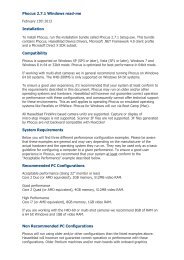
<strong>Hasselblad</strong> 500 EL/M Camera2Camera Controls:1) Operate Push button2) Mode Selector (taped)3) Lens Cocking Tool (Under tape)4) Remote Connector5) Battery Compartment6) Battery Compartment Lock7) Lens Release ButtonFilm MagazineControls:14 11 12a 4 12b 3 2 1 138) Magazine Release Button9) Magazine Insert Lock (Taped)10) Darkslide11) Frame Counter12a) End of Film Indicator12b) Film Advance Indicator
3Viewfinder Controls:13) Prism Viewfinder14) Diopter Correction Eyepiece15) Lock for Correction Eyepiece16) Rubber Eyecup7 5 8 10 6 9 15 16
<strong>The</strong> EL/MPower SupplyReleasing the Camera4<strong>The</strong> electric film advance is powered bytwo 6V rechargeable nickel cadmiumbatteries located in the battery compartment.Two fully charged batteries providepower for approximately 2000 exposuresand changing the batteries should not benecessary. A slowing down of the windingcycle, however, indicates low batteryvoltage and that both batteries need to bechanged.<strong>The</strong> battery compartment is opened byturning the slotted compartment lock (6)counter clockwise to the vertical positionusing the lens cocking tool (3). Removethe compartment cover (Fig. 1). Alwaysremove both batteries and insert onespare battery in either compartment. Batteries(A) are inserted with the (+) end first(Fig. 2). Properly inserted, the batteriesrest on a spring and can be pushed up&down. When inserted the wrong way, thecover cannot be closed easily and maybe permanently bent. Do not force. Checkposition of batteries. Cover is re-attachedby placing the hooks at the front of thecover into the openings (D) in the camerathen pressing the rear firmly towards thecompartment while turning the slotted lock(6) clockwise to the horizontal (locked)position.NOTE: Camera operates only if a fuse in goodcondition is in the fuse receptacle. <strong>The</strong> fuse (C)can be replaced and inserted in (B) either way.<strong>The</strong> image is recorded on the film bypressing the operate push button. <strong>The</strong>shutter is re-cocked, and the film advancedto the next frame, when removingthe finger from the button. A second exposurecan be made as soon as the windingcycle is completed. If the camera does notoperate when the release is depressed:1. Darkslide may be inserted in filmmagazine. Remove it.2. <strong>The</strong>re may be no film left in magazine.Check film load signal (12a) if red,change magazine.3. <strong>The</strong> fuse is dead. Replace.4. <strong>The</strong> batteries may have no charge left.Replace.FIGURE 1 FIGURE 2 FIGURE 3
Remote OperationCamera Steadiness5Camera can also be released with remotecable, Remove socket cover (Fig. 3) byturning it counter clockwise and attachremote release cable to remote connector4. <strong>The</strong> camera operation is determined bythe position of the mode selector (page 6)one picture in position 0 - or sequences inposition A.<strong>The</strong> camera must be perfectly steadywhen the exposure is made. Camera motionwhile the film is being exposed canresult in unsharp pictures. Reduce thedanger of camera movement by:1. Holding camera firmly with both hands,one hand on the bottom, the other ontop (Fig. 4&5). 2. Pressing both elbowsinto your body for additional support.3. Pressing rubber eyepiece of the viewfinderagainst your viewing eye to forma firm contact between the foreheadand finder (Fig. 6).4. Holding Breath.5. Pressing the operate push buttonslowly and gently so you are hardlyaware when the exposure is madeand keeping it depressed until theexposure is completed. Don't jerk therelease or depress it rapidly.NOTE: Perfect camera steadiness is importantwith aIl lenses - but more so with the 250mmSonnar. <strong>The</strong> long focal length magnifies camerashake.FIGURE 4 FIGURE 5 FIGURE 6
Operating ModesFilm Magazines61) <strong>The</strong> mode selector is set at 0 at launchand taped over (Fig. 7). Do not removethe tape and change the setting exceptfor automatic sequence operation.2) For automatic sequence operation(1 picture per second) remove tape,change selector to A (Fig.8). Whenthe release is depressed, the cameratakes pictures at regular intervals of1frame/second as long as the releaseis kept depressed - and as long asthere is film in the camera. When sequenceis completed, change dial backto 0 and re-tape.To attach a film magazine to the camerabody, hook the magazine onto thetwo lower support catches (E) (Fig. 9),swing the top of the magazine firmly andcompletely against the upper catches (F)and camera body while at the same timesliding the magazine release button (8) tothe right (Fig. 10). After the magazine isattached remove darkslide (Fig. 9a).To remove a magazine, insert darkslide(10) slide magazine release button (8) tothe right (Fig.11), lift off magazine (Fig.12).NOTES: a) Magazines cannot be attached orremoved unless darkslide is inserted. b) Neverremove the darkslide from a magazine that isnot attached to the camera. It would exposesome of the film in the magazine.OPERATlNG SIGNALS: (Fig. 13)<strong>The</strong> film magazine includes a frame counter(11) which counts up and indicatesnumber of frames exposed. Check oncein a while so you do not run out of film inthe middle of an important picture takingsequence. <strong>The</strong>re are about 120 frameson a roll of film. <strong>The</strong>re is also an end offilm indicator (12a). It turns from white tored when the roll of film is finished and atthat moment the camera will stop operating.Film advance indicator (12b) goesfrom white to red to white to show film isadvancing properly.FIGURE 7FIGURE 8
7FIGURE 9FIGURE 10FIGURE 11FIGURE 9aFIGURE 12FIGURE 13
Film Magazines withDatabacksPermanently AttachedDatabackDataback withRemovable Module8Some or all film magazines used on yourmission may be equipped with a databack.It may be permanently attached to themagazine (Fig. 14) or have a removableelectronics module which can be switchedfrom one magazine to another (Fig. 15).<strong>The</strong> film magazine of either version is attachedto the camera body, as is the regularmagazine 100/200 but the magazinerelease button (8) is pushed towards theleft (not right). To remove a film magazine,push the magazine release button againtowards the left (Fig. 14).Proper operation is indicated by a greenLED at rear. Check whether it goes on andoff after the exposure. This indicates thatthe data recording has been successful.<strong>The</strong> electronics module is removed by depressingthe latch and sliding the moduletowards the rear. It can now be attachedto another magazine in the same fashionby depressing the latch again (Fig. 15). Itis made operative with the On/Off Switch.Make certain that the exposure settingswitch is set for the ASA rating of the filmin that particular magazine.Position 1 for ASA 25 - 100Position 2 for ASA 100 - 400Position 3 for ASA 400 - 1600Position 4 for ASA 1600 - 6400Instructions for the correct setting will besupplied.A green LED lights up momentarily at theend of each shot to indicate a successfuldata recording.Malfunctioning or low battery power isindicated by a red LED. <strong>The</strong> batteries,however, have sufficient power for anentire flight.FIGURE 14 FIGURE 15
Changing Lenses9To remove a lens, press lens releasebutton (7) and turn lens counterclockwiseabout 1/10 turn (Fig. 16). To attach a lens,match red marking on lens barrel with redmarking on camera body (Fig. 17). Turnlens firmly clockwise until it clicks positivelyin place (Fig. 18). Do not depress lensrelease button when attaching a lens.b) Lenses can be attached only if the camerabody is cocked and the shutter in the lens isalso cocked (open). (Shaft J) in lens is oppositered dot (L) (Fig. 19). If a shutter shouldhave been closed accidentally while lens wasremoved from camera insert lens cocking tool(3) located under the taped mode selector (2)in shaft slot (M). Make a full turn clockwise inthe direction of the arrow. (Fig. 20)NOTES:a) Lenses can be removed only when the shutteris cocked, which is normally the case onthe EL/M. <strong>The</strong> lens could be uncocked onlyif the camera stops before completing thecycle due to low battery power, or if a fuseis blown. If so change batteries to completecycle or change fuse.FIGURE 18FIGURE 19FIGURE 16 FIGURE 17FIGURE 20
LensesLens Controls10<strong>Hasselblad</strong> cameras may be equippedwith either "C" lenses or "CF" lenses. <strong>The</strong>"c" lenses have a VXM lever on the leftside (Fig. 21)This control is only on the "C" lenses (Fig.21), not the "CF" types (Fig. 22). Otherwise,the lenses differ only in the locationand operation of the lens controls.17) Focusing Ring with distance engravings18) Lock for "F" setting ("CF" lens only)19) Aperture Setting Ring with aperture engravings20) Shutter Speed Ring with shutter speed engravings21) Index for distance, aperture &shutter speed22) EVS Engravings23) Index for EVS Setting24) Lever for unlocking aperture & shutter speed (on "c" lenses only)25) Button for interlocking aperture and shutter speed rings (On "CF" only)26) Movable depth of field indicators (on "c" lenses only)27) Engraved depth of field indicators (on "CF" lenses only)28) Flash Sync Lever, (must be on X or M) (on "c" lenses only)29) Flash cable connector30) <strong>Manual</strong> diaphragm stop downC LensCF LensFIGURE 21 FIGURE 22
11C LensesFIGURE 23FIGURE 24CF LensesFIGURE 25FIGURE 26FIGURE 27FIGURE 28
ViewingDiopter Adjustment12<strong>The</strong> prism viewfinder (13) provides amagnified, upright and laterally correctimage. Make certain that you always seethe entire square groundglass screen fromcorner to corner. This requires placingyour eye firmly against the rubber eyecup(16) and in the optical center of the eyepiecelens (Fig. 29 & 31).This is especiallyimportant when photographing through thewindows in the space shuttle. You may notsee a window frame cutting into part of theimage unless you move your eye aroundthe viewing screen. <strong>The</strong> rubber eyecupwhich 0ffers a comfortable support forviewing can be turned for left or right eyeviewing. Pressing eye and forehead firmlytowards the viewfinder eyepiece alsoprovides an important camera support forincreased camera steadiness.NOTE: It is recommended that you removeyour eyeglasses. Eyeglasses prevent the closecontact between eye and eyepiece. <strong>The</strong>y alsoallow objectionable light to enter between theeyeglasses and eye. (Fig. 31).FIGURE 30<strong>The</strong> prism viewfinder is equipped with anadjustable eyepiece (14) (Fig. 29). It maybe adjusted to your eyesight for accuratefocusing and strain-free viewing. Removelens from camera. Remove eyeglasses.View through finder and turn diopteradjusting ring (14) until the groundglassscreen appears critically sharp. Removethe eye, relax it for a moment by lookingat infinity, and view through the finderonce more to ascertain that the screen isstill sharp. <strong>The</strong> eyepiece is now adjustedto your eyes. Lock it with screw (15) (Fig.29).NOTES:a) It is suggested that you read the dioptersetting after adjusting the eyepiece to your eyesight(-1 in Fig. 30). This makes it unnecessaryto repeat the diopter adjustment after someoneelse uses the camera simply set it to your predeterminednumber (-1 for example) and lock it.b) If you cannot view without eyeglasses,make the adjustment on the diopter correctioneyepiece with the glasses on. c) <strong>The</strong> viewfinderis not meant to be a handle for carrying thecamera.d) Should the image in the finder appear darkthe diaphragm in the lens is probably stoppeddown. To re-open it, proceed as describedunder "lens aperture" (Page 22).FIGURE 29 FIGURE 31
Focusing13<strong>The</strong> prism finder is also used for focusingthe lens (setting the lens for the camera tosubject distance). <strong>The</strong> groundglass screenis split into various sections (Fig. 32):(A) Groundglass screen area.(B) Bright microprism area.(C) Split image rangefinder.NOTES:a) With the 250mm lens, one of the range finderfields remains dark. Focusing must be done inthe microprism or groundglass area.b) <strong>The</strong> image always appears sharp in therangefinder area, so you must have a straightline intersecting the split.<strong>The</strong> distance is set by turning the focusingring on the lens until one or more of thefollowing conditions are achieved:1) <strong>The</strong> image (Fig. 33a) appears sharpon the groundglass (Fig. 33b).2) You see a fine detailed image withinthe microprism area (Fig. 33b).3) A straight line crossing the split in therangefinder (Fig. 34a) appears unbroken(Fig. 34b).FIGURE 32 FIGURE 33 FIGURE 34
Focusing SuggestionsDepth of Field141) For fast and accurate focusing, turnthe focusing ring quickly back and forthover the point of sharpness makingsmaller and smaller back and forthmovements until the point of sharpnessis locked in. This is better thanturning the focusing ring slowly in onedirection towards the point of focus(Fig. 36).2) Do not try to focus visually for earthshots, simply set lens at infinity.3) If all the important elements are at thesame distance (not some closer andsome further away), simply turn the focusingring until these subjects appearsharp in the finder.4) If important subjects are at differentdistances (in front & rear of cargo bayfor instance) try to set the lens so thatboth are sharp. That means setting thelens for depth of field.NOTE: <strong>The</strong> CF lenses have distance scales infeet and meters. <strong>The</strong> footage scale is in orange,the meter scale in white.FIGURE 36<strong>The</strong>oretically, on Iy subjects that areexactly at the focused distance (Fig. 37)appear sharp on the film. Sharpnessgradually falls off in front of and beyondthe set distance. On the photographic printor transparency, however, some degree of"unsharpness" is acceptable. This rangeof acceptable sharpness is called depthof field. One third of the total depth of fieldis in front of the focused distance and twothirds beyond (Fig. 37).<strong>The</strong> depth of field scale on the lens isused to determine the depth of field range.On <strong>Hasselblad</strong> C lenses (Fig. 38/39)depth of field is indicated by the two redpointers which move automatically asthe aperture ring is turned. <strong>The</strong> distancesopposite the two red pointers indicate therange of acceptable sharpness.On the <strong>Hasselblad</strong> CF lenses, the depth offield is engraved (Fig. 40/ 41 ). Read theclose and far distances opposite the twowhite lines corresponding to the apertureset on lens (11 if lens set at f/11 ).<strong>The</strong> depth of field range depends mainlyon the lens aperture. At large apertures(f/5.6 in Fig. 38 &40) depth of field is lessthan at small apertures, (f/22 in Fig. 39 &41 ).
15Depth of Field at different aperturesFIGURE 38Large Aperture givesshallow depth of fieldFIGURE 39 FIGURE 40Small aperture givesLarge aperture givesgreat depth of fieldshallow depth of fieldFIGURE 37FIGURE 41Small aperture givesgreat depth of field
Depth of Field with Different Lenses16Depth of field also varies with lens focallength. <strong>The</strong> 50mm lens (Fig. 43) hasmore depth of field than the 100mm (Fig.44). <strong>The</strong> 250mm (Fig. 45) has less if thelenses are used from the same distance(each lens covers a different area).<strong>The</strong> 50mm has depth of field from 50 feetdown to 7 feet (Fig. 43) the 100mm at thesame aperture from 50 feet only down to17 feet (Fig. 44), while the 250mm goesfrom 50 feet only down to 40 feet (Fig. 45).NOTE: Sharpness beyond the depth of fieldrange falls off more rapidly with the longerlenses. Backgrounds are blurred more with the250mm than the 50mm wide angle.50mm 100mm 250mmFIGURE 43 FIGURE 44 FIGURE 4550mm Wide Angle has depth offield from 50' down to 7'100mm standard has depth of fieldfrom 50' down to 17'250mm Telephoto has depth offield from 50' down to 40'
Focusing for Depthof Field17If subjects at different distances are to berecorded sharply, set the lens for depth offield. Proceed as follows:1) Focus the lens at the farthest subjectto be sharp. Read the distance on thescale (30') (Fig. 46).2) Focus the lens at the closest subjectto be sharp. Read the distance on thefocusing scale (8') (Fig. 47).3) Set the lens, so the two distances arewithin the depth of field indicators (Fig.48).NOTE: If the two distances cannot be placedwithin the depth of field range (because ofexposure requirements), decide whether it ismore important to have the background or theforeground sharp, and set the lens accordingly.FIGURE 4630' is the farthestsubject distance
Focusing for Depth of Field18FIGURE 478' is the closest subject distanceFIGURE 4814' is the distance set on lens
Use of Lenses19Three different focal length lenses areused on <strong>Hasselblad</strong>. <strong>The</strong> focal lengthengraved on the lens determines theangle of view and thus the size of the areaincluded in the picture.1) <strong>The</strong> 100mm Planar has a diagonalangle of view of 43°. It is called a standardlens as it records an image on thefilm that looks in a "natural" perspective.Subjects at different distancesfrom the camera appear as we seethem with our eyes.2) <strong>The</strong> 50mm's wide angle of view(measured diagonally) is 75°. It coversa larger area from the same distanceand includes large background areas(e.g. a large part of the earth). Subjectsare recorded smaller comparedto the standard lens. Backgroundappears farther away. It enhances thesize relationship of subjects close andfar.3) <strong>The</strong> 250mm telephoto has a narrowerangle of view of 18°. It coversa smaller area, and magnifies thesubject, (2% times compared to the100mm lens). It includes small backgroundareas (e.g. small part of earth)and compresses perspective. Distantsubjects appear closer.<strong>The</strong> 50 mm wide angle (top) covers a largerarea, and the 250 mm telephoto (bottom) asmaller area than the 100mm "standard" whenused from the same distance. With the wideangle, distant subjects are smaller and thusappear further away. <strong>The</strong> telephoto magnifiessubjects and brings them closer.A short focal length lens (top) covers a largebackground area (from a to b). A longer focallength lens used from a longer distance (bottom)covers a smaller background area (from cto d) while the main subject (the model) is thesame size in both.Different focal length lenses can also be usedto cover the same area by photographing fromdifferent distances. While the subject size is thesame, the perspective is not.
Use of Lenses201 2 3<strong>The</strong> cargo bay area photographed with differentfocal length lenses. <strong>The</strong> 100mm (1) records thearea as normally seen, the 50mm wide angle(2) makes it appear longer and the 250mmtelephoto (3) magnifies the distant details.1 2<strong>The</strong> use of different focal length lenses tophotograph the earth - 100mm (1), 250mmtelephoto (2).
211 2<strong>The</strong> 50mmm wide angle used in (1) madethe church appear to be far away from thesign. With the telephoto (2), used from alonger distance, the sign is recorded ofequal size but the church appears muchcloser. This size relationship between foreand background is known as perspectiveand is determined by the camera/subjectdistance. <strong>The</strong> wide angle lens (1) alsoincludes a much larger background areathan the telephoto.3 4A small lens aperture (f/22) with its large depthof field produces an image as we see it withour eyes (3). <strong>The</strong> shallow depth of field at alarge aperture (f/4) produces an image that ispictorially more striking, and can be used toblur foreground and background to enhance aparticular subject (4).
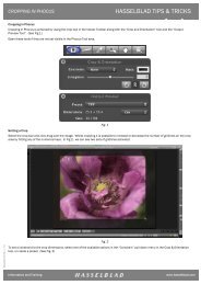
Lens Aperture22<strong>The</strong> lens aperture indicates the diameterof the diaphragm opening. It changes byturning the aperture ring. In addition todepth of field it also controls the amount oflight that reaches the film.At a high f number, (22, for instance) thediaphragm opening is small, and lets inless light (Fig. 49). At a small f number,(4, for instance) the diaphragm opening islarger, and lets in more light (Fig. 50).NOTE: <strong>The</strong> lens aperture is normally fully opento provide the brightest image for viewing. Incase the groundglass imageappears darker than normal, the aperture mayhave stopped down accidentally. If so, re-openit by doing the following: For "C" lenses. Turnthe aperture ring until the maximum aperture(smallest f#) is opposite the white index. Thismay require uncoupling aperture & shutterspeed ring by depressing lever (24) towardscamera body, (Fig. 51), and turning aperturering (19) alone to max. aperture, (smallest number).Re-set the ring to the correct aperture andshutter speed combination. For "CF" lenses.Depress the bottom of the stop down lever (30)and push the entire lever upwards (Fig. 52).High f number is small apertureLow f number is large apertureFIGURE 51FIGURE 49 FIGURE 50 FIGURE 52
Shutter SpeedSetting Aperture &Shutter Speed23<strong>The</strong>re is also a shutter in each lens. Itopens and closes when the release isdepressed. <strong>The</strong> length of time the shutterstays open is set on the shutter speed ringengraved from 1 to 500 meaning 1 secondto 1/500 second.<strong>The</strong> longer the shutter speed, the longerthe film is exposed to light. Changing theshutter speed from 1/125 to 1/250 sec.makes the image darker - changing from1/125 to 1/60 makes it one stop lighter.Whenever possible, select short shutterspeeds when using the camera handheld.Leave the shutter speed at 1/250 sec.Change to a slower speed only when lowlight levels require it, and if so, do not gobelow 1/60 sec. and then only with the 50and 100mm lenses. Never use a speedslower than 1/250 sec. with the 250mmSonnar.NOTE: In case shutter speed ring on CF lenseshas accidentally moved to the green F setting,depress green lock button (18) and re-set ringto correct shutter speed,On some "C" lenses and on all "CF"lenses, aperture and shutter speed ringsare not coupled. Each can be turnedindependently. <strong>The</strong> two rings on the "CF"lenses can also be coupled by depressinginterlocking button (25) (Fig. 53).On some lenses, aperture and shutterspeed rings are coupled. <strong>The</strong>y bothchange together while turning knurledfront ring (20). As you change the aperture(e.g. from f/4 to f/8) the shutter speedchanges (from 1/250 to 1/60).You can set the aperture separately bypressing the cross coupling lever (24) tothe rear and turning the aperture ring (19)(Fig. 51). With the cross coupling leverpushed towards the rear, you can alsochange the shutter speed separately byturning the shutter speed ring (20) with theother hand.Coupling aperture and shutter speed ringoffers the advantage that all the interlockedsettings provide exactly the sameexposure. (See page 24).FIGURE 53
ExposureChanging Aperture &Shutter SpeedExposure from charts24<strong>The</strong> film in the camera must receive aspecific amount of light to produce aproperly exposed image. <strong>The</strong> total amountof light that reaches the film is determinedby the combination of aperture size andshutter speed. <strong>The</strong> same exposure can beobtained with a longer shutter speed andsmall aperture or a short shutter speedand large aperture. Changing from a lowf number to the next (f/8 to f/11) meansletting in only half the amount of light. Youcan compensate for this loss of light byletting the light go through the lens twiceas long, i.e. setting the shutter speed at1/125 instead of 1/250.With the aperture and shutter speed ringsinterlocked, all combinations give thesame exposure. To say it in a differentway, if you change the aperture or shutterspeed on the interlocked rings the shutterspeed or aperture size automaticallycompensates. To increase or decreasethe light going through the lens, you mustunlock the coupling and change either theaperture only or the shutter speed only, orboth.<strong>The</strong> necessary lens settings for correct exposurecan be obtained from charts, fromprevious experience or from an exposuremeter.A general exposure setting can be used tophotograph any part of the earth but onlywhen the sun is at or near maximum sunangle i.e. approximately 10 a.m. to 3 p.m.When the sun is at an angle of less than30°, lens aperture must be opened one ortwo f stops to avoid underexposure. Consultthe sun angle exposure chart suppliedfor your mission.In summary, for earth shots, determinethe sun angle, then consult the sun anglechart and set each lens accordingly. Neveruse the spotmeter for determining the lenssettings for earth shots.
<strong>The</strong> Exposure Meter252 MEMORY CLEAR3 ASA/TIME SELECT4 TRIGGER5 VIEWFINDER DISPLAY ILLUMINATIONBUTTON9 OFF/ON SWITCH10 SHADOW BUTTON11 AVERAGING BUTTON12 HIGHLIGHT BUTTON14 ASA/TIME INCREASE BUTTON15 ASA/TIME DECREASE BUTTON16 VIEWFINDER EYEPIECE18 EV/ F NO. SELECT BUTTON19 RECALL (MEMORY)20 MEMORYNOTE: <strong>The</strong> meter is battery powered.<strong>The</strong>re are no spares on-board.Indication of bad batteries is a flashing meterdisplay.FIGURE 55
ASA/Shutter SpeedSettingViewfinderOperating Meter26Before you use the exposure meter ascertainthat it is set for the ASA rating of thefilm in the camera and the shutter speedset on the lens. <strong>The</strong> ASA rating is indicatedon the <strong>Hasselblad</strong> film magazine.Turn meter on by sliding the on-off switchto ON. Check the ASA setting by depressingthe ASA/Time select key (3). ReadASA. If number is too low, depress ASA/Time increase key 1 (114) repeatedly untilthe right value appears. If too high, depressthe ASA/Time decrease key ↓ (15)repeatedly until the ASA value is correct.Check the shutter speed setting bydepressing the ASA/Time key (3). If theshutter speed is lower than the cameradepress the increase key 1 (14) repeatedlyuntil the shutter speed corresponds(120 for 1/125 sec.) If too high, depressthe decrease key! (15) repeatedly untiI thevalue corresponds.NOTES: <strong>The</strong> display should not show a smallS or M (this would indicate seconds or minutesrather than fractions of a second.) <strong>The</strong> ASA andshutter speed display can only show 0 in thethird and fourth digit Thus 64ASA will appear as64; a 1/ 125 shutter speed as 120.Adjust the viewfinder to your eyesight byturning the eyepiece guard (16) until the10 circle engraving appears sharp.NOTES: Meter readings should always bemade with the eye covering the eyepiece toprevent light entering the ocular and affectingthe meter reading.Exposure reading is not affected by the eyepieceadjustment Never point meter directly atthe sun.To take a meter reading, place the 10circle over the area you want to measure(Fig.56). Press and hold the releasetrigger (4) until a reading appears in thefinder LCD display. After the display stopschanging release the measure button tohold the reading. Set aperture on lensaccording to reading in display window(Fig. 57).<strong>The</strong> meter reading (the f number) can beread in either of three places: 1) digitaldisplay on side, 2) indicator above sidedigital display, and 3) digital display inviewfinder.<strong>The</strong> digital display of f/stop indicates"Tenth's of a stop" as a small or subscriptnumber. This can be rounded off to thenearest 1/2 stop. For example a small0 behind number 5.6 (Fig. 57) indicatesexactly f/5.6. <strong>The</strong> f#8.03 (Fig. 58) means3/10 of an f stop smaller than f/8, (lesslight than f/8). Set aperture between f/8and f/11.FIGURE 56 FIGURE 57
Determining Lens Settings withExposure Meter27If an "E" (error) appears in the numberdisplay, it means the range of the meterhas been exceeded. Some parameterneeds to be changed shutter speed and/or film type.Meter remains active for 2 minutes after itis turned off.NOTES: Meter readings can be taken onlywhile in the TIME mode not ASA mode. F No/EV key should not have to be actuated. <strong>The</strong>meter is launched in F No mode.Do not depress shadow (10) or highlight (12)buttons.A basic understanding of light measuringwill help you to use the exposure meterproperly.<strong>The</strong> lens settings that provide correctexposure are based on the amount of lightfalling on the subject you photograph, notreflected off the subject. <strong>The</strong> lens settingsmust be the same whether you photographa subject that is white, gray, black,yellow, red, green or blue or whateverthe color might be as long as the sameamount of light (X in Fig. 59) falls on them.Your meter, however, does not measurethe light that falls on the subject, but thelight reflected off the subject. Its reading isbased onthe amount of light reflected off the verysmall area inside the circle in the meterfinder. <strong>The</strong> meter reading is different if youpoint the meter at a white, gray, black,green, blue, or red area even though thesame amount of light falls on all (Fig. 60).Point the center circle of the meter at grayor green, it might show f/11 at white or yellowf/22 and at black or dark brown f/5.6.Which is correct?<strong>The</strong> readings shown on your meter arecorrect only when the center circle ispointed at a subject or area that reflectsapproximately 18% of the light. It is incorrectwhen the reading is taken off an areathatFIGURE 58 FIGURE 59 FIGURE 60
Determining Lens Settings withExposure Meter continued28reflects more or less. If you set the lens forthe white reading (f/22 1/125), white wouldbe recorded as gray, not white. <strong>The</strong> imageis underexposed. A lens set for the blackreading (f/5.6 1/125) would record blackalso as gray, not black. <strong>The</strong> image is overexposed.This problem can be overcomein various ways:A) Whenever possible, point the centercircle at an area that reflects approximately18% of the light - green, lightbrown, gray - and use the indicatedsetting.B) Point the center circle at whateverarea is most important then try toestimate whether the area in the circlereflects more or less than 18% and ifso adjust the lens setting. When readinga bright (white) area open apertureone to two f stops (Fig. 62a). Whenreading a dark area, close apertureone to two f stops (Fig. 62b).For shuttle space photography, the following corrections should be used. <strong>The</strong>se correctionswill produce slightly underexposed transparencies which are desired for duplication.For white only scenes:Reading off white cargo bay:Reading off white space suits:Reading off blue space suits:Reading off suntanned fleshtones:Reading off black fleshtones:Reading off black only scenesOpen 1 stop (f/11 instead of f/16)Open 1 stopOpen 1 stopClose ½ stopCorrectClose 1 stopClose 1 stop (f/11 instead of f/8)FIGURE 62
Exposing for Sunor Shade?Exposing for SlidesHigh Contrast Scenes29Frequently some areas included in aphotograph are in sunlight, some in theshade. Pointing the meter into the sunnyarea (of the cargo bay for instance) givesa higher reading than from the shadedarea (Fig. 63). Which exposure is correct?This depends on the type of film in thecamera.Exposing forNegative FilmNegatives need shadow details. Lenssettings, therefore, must be based on theamount of light falling in the shaded area:the shaded side of the cabin, astronautsface or suit, or the shaded side of thecargo bay (Fig. 63b). Point the meter atthe shade. Open the lens one f stop if theshaded subject is white.Slides look best when exposed for thelighted areas even though there maybe little detail in the shade. It preventswashed out highlights without color andcontrast. With slide film (Ektachrome)therefore, point the meter at a subject inthe lighted area, (<strong>The</strong> sunny side of thecargo bay, (Fig. 63a) the sunlit area insidethe cabin, the sunlit side of the astronautsface or space suit, the sunlit side of asatellite). A correction needs to be appliedto the spotmeter reading if the subject isnot 18% grey. For bright white subjects,open the lens one f stop (lower number)from spotmeter reading. Exception: If it ismore important for record purposes to seedetails in the shade rather than producinga pictorially good looking slide, you shouldexpose for the shade. This, for instance,could be the case when you need torecord the launching of a satellite or thework of the astronauts in the shade of thecargo bay. If so, try to compose the imagein such a way that the sunlit areas are notvery large and not in the center wherethey are distracting. Bright areas attractattention!Slides exposed for the lighted area, asexplained, usually look best. In a highcontrast scene where it is desirable tosee details in the lighted and dark areas,take a meter reading of both and set theaperture in between the two.FIGURE 63Bracketing ExposureFollowing these suggestions, exposureshould be extremely accurate - no needfor bracketing which means taking the,same image at different lens settings. Indoubtful cases, or when the contrast betweenlight and dark is very high, bracketingis recommended when time permits.Take the picture at the meter setting,then take additional pictures at one f stophigher and one f stop lower.
Exposure techniques30It is impossible to have "perfect" exposure forthe shaded cargo bay and sunlit earth at thesame time. Since the cargo bay with the OrbitalManeuvering System burn is the more importantpart, the above image is properly exposedto make the best looking transparency.<strong>The</strong> spotmeter reading can vary within severalf stops depending whether it is pointed at darkor light colored subjects. It is correct whenpointed at subjects that reflect about 18% ofthe light such as the brown building, the bluesky, and the gray board in the foregroundwhich all show f/11.Slides look best when exposed for the lightedareas. <strong>The</strong> spot meter should therefore bepointed at a lighted area (P [positive film]).Negative films need shadow details. <strong>The</strong> spotmeter is therefore pointed at a shaded area (N).
Composition31<strong>The</strong> effectiveness of an image is greatlydetermined by the arrangement of lines,shapes, and colors within the square area.This is known as composition. Evaluatethe arrangement of these elements on thescreen and try to frame the scene so itlooks like a pleasing, balanced image thatkeeps the viewers eye within the frame.1) Single subject.If the scene is dominated by one singlesubject (a satellite being launched),place the subject in the center of theframe. It is a static image but all attentionis then automatically focused onthis subject (Fig. 64).2) Balance.An important subject, dominant line,shape on one side of the image, oron top or bottom must be balanced bya second, somewhat less dominantelement on the other side (Fig. 65). Donot have all the elements that attractthe eye on one side. <strong>The</strong> image "fallsover." (Fig. 66).3) Color balance.Colors must also be considered forbalance. Try to balance a subject of aspecific color on one side by a secondsubject of the same or similar color onthe other side.FIGURE 64 FIGURE 65 FIGURE 66
Composition continued324) Rule of thirds.In scenes including more than oneimportant element, place the mostimportant line, shape and color approximately⅓ from the left, right, topor bottom (Fig. 67).5) Placement of horizon.<strong>The</strong> horizon, the outline of the earth isfrequently a dominant line. Avoid placingit through the center splitting theimage into two equal halves (Fig. 68).Place the line 1/3 from top or bottom(Fig. 69).6) Diagonals.Horizontals are static, diagonals aredynamic. Framing the outline of theearth, features on the earth, or parts ofthe space shuttle as diagonals makesa more striking image (Figs. 70, 71 ).7) <strong>The</strong> leading line.A slanted line starting at the bottom ofthe frame can be used to lead the eyetowards the main subject (Fig. 72).8) Attention creating elements.In any image the eye is attracted by:a) <strong>The</strong> brightest area, regardless howsmall.b) <strong>The</strong> “one of a kind thing” - a coloror shape that is different from allthe rest, a line going in a differentdirection than the rest (Fig. 73).c) A dark line or shape next to white.d) A line broken by the frame of theimage (Fig. 74).Use these elements to attract attention.Avoid them if they are unimportant.FIGURE 67 FIGURE 68 FIGURE 69
33FIGURE 70 FIGURE 71FIGURE 72FIGURE 73FIGURE 74
Obtaining the Most Effective Images34<strong>The</strong> effectiveness of the image dependson sharpness, correct exposure, goodcomposition and lighting.Frontlighting: <strong>The</strong> sun illuminating thesubject from the front, is the least effective.Everything is evenly lit, flat withoutshadows and highlights.Sidelight: From a photographic point ofview, sidelight produces more effectiveimages. Some areas are in the shade,some in the light. <strong>The</strong> result is a threedimensional effect which enhances detailsand textures. <strong>The</strong> increased contrast alsomakes the images appear sharper.Areas on earth are lit by sidelight only inearly morning or late in the afternoon. Itproduces, photographically, the most effectiveand sharpest looking images. Thisis true especially of areas that are of equalcolor, e.g. flatland, deserts. Lens settingsmust be adjusted for low angle sunlight.See exposure. Clouds photographed insidelight take on a fluffy shape, and arenot just patches of white.Backlight: <strong>The</strong> sun shining towards thecamera, can be even more effective - butmainly for effect, not documentation. Sunlight reflecting on water surfaces can bevery striking. <strong>The</strong> contrast is usually toohigh to see details in the shaded and lightedareas. You must expose for one or theother depending on the film. See exposurepage 29. Unless details are necessary inthe shaded area, expose slide film for thesunlit background, such as sky or earth.Camera Angle: Best quality with mostdetails in earth shots is usually obtainedby photographing straight down, not atan oblique angle. Oblique angle shotsare more likely to look flat and hazy, butthis can be pictorially effective becausethey show a large area of the earth withthe curved outline of the horizon in thebackground.Sun Protection: Direct sunlight shouldnever shine directly on the lens. It producesflare - a loss of contrast. Hold thecamera so the lens is shaded from directsunlight. If not possible, place your handover the lens to form a sunshade, naturallymaking certain the hand does not showup in the picture. Check the image on thegroundglass screen.<strong>The</strong> sun shining on a shuttle window alsoproduces a hazy picture. Try to shootthrough a window that is shaded fromdirect light. Always try to shoot as straightas possible through the window, not at anangle. <strong>The</strong> top cabin window is usually thecleanest and therefore produces the bestresults.
Obtaining the Most Effective Images35<strong>The</strong> sharpness and contrast of the imageis decreased immensely when recordedthrough dirty, greasy glass. Clean the windowsin the shuttle before you photographthrough them. Clean the lens surfaceswith the lens cleaning kit. Don't just cleanthe front element, but the rear element aswell, especially when changing lenses.Clean front and rear surfaces before youattach the new lens.Properly exposed to render the clouds as white as they should be, thisphotograph silhouettes the shuttle and space walker for a dramaticvisual effect. <strong>The</strong> reflections of the clouds on the lower left help thecomposition by "balancing" the white from the top. Good use of aleading line - the right side of the cargo bay leads the eye to the spacewalking astronaut.<strong>The</strong> beautiful quality of a strong sidelight is illustrated in this shot of aSatellite Business System deployment. It brings out the patterns, thedetails in the cargo bay and the SBS. Since the SBS is the one andonly important subject, it is properly composed in the center of theframe.
Obtaining the Most Effective Images continued36<strong>The</strong> effectiveness, sharpness and three dimensionalfeeling that a low sun angle creates isbeautifully illustrated in this view of the Kamchatkapeninsula in the U.S.S.R. <strong>The</strong> diagonalshore line adds to the effectiveness from acompositional point of view.Sunlight reflected on water surfaces can producea most striking image.A low sun angle helps especially when photographingdeserts or other land areas where theentire landscape is of the same or similar color.
Space <strong>Photography</strong>37<strong>The</strong> blue area attracts immediate attention because it is the onlyblue in the picture. It is properly composed in the center.A striking example of the beautiful and dramatic light quality createdby a low sun angle.<strong>The</strong> future possibilities in space are beautifully documented inthis <strong>Hasselblad</strong> photograph of an untethered space walker.<strong>The</strong> diagonal earth line creates a more dynamic image.© 1984 Victor <strong>Hasselblad</strong> Inc./NASAPublished and Printed in USA.