Sun StorEdge 3000 Family Installation, Operation, and Service Manual
Sun StorEdge 3000 Family Installation, Operation, and Service Manual
Sun StorEdge 3000 Family Installation, Operation, and Service Manual

You also want an ePaper? Increase the reach of your titles
YUMPU automatically turns print PDFs into web optimized ePapers that Google loves.
<strong>Sun</strong> <strong>StorEdge</strong> <strong>3000</strong> <strong>Family</strong><strong>Installation</strong>, <strong>Operation</strong>, <strong>and</strong> <strong>Service</strong><strong>Manual</strong><strong>Sun</strong> <strong>StorEdge</strong> 3510 FC Array<strong>Sun</strong> <strong>StorEdge</strong> 3511 FC Array with SATA<strong>Sun</strong> Microsystems, Inc.www.sun.comPart No. 816-7300-16May 2004, Revision 01Submit comments about this document at: http://www.sun.com/hwdocs/feedback
Copyright © 2004 Dot Hill Systems Corporation, 6305 El Camino Real, Carlsbad, California 92009, USA. All rights reserved.<strong>Sun</strong> Microsystems, Inc. <strong>and</strong> Dot Hill Systems Corporation may have intellectual property rights relating to technology embodied in this productor document. In particular, <strong>and</strong> without limitation, these intellectual property rights may include one or more of the U.S. patents listed athttp://www.sun.com/patents <strong>and</strong> one or more additional patents or pending patent applications in the U.S. <strong>and</strong> other countries.This product or document is distributed under licenses restricting its use, copying distribution, <strong>and</strong> decompilation. No part of this product ordocument may be reproduced in any form by any means without prior written authorization of <strong>Sun</strong> <strong>and</strong> its licensors, if any.Third-party software is copyrighted <strong>and</strong> licensed from <strong>Sun</strong> suppliers.Parts of the product may be derived from Berkeley BSD systems, licensed from the University of California. UNIX is a registered trademark inthe U.S. <strong>and</strong> in other countries, exclusively licensed through X/Open Company, Ltd.<strong>Sun</strong>, <strong>Sun</strong> Microsystems, the <strong>Sun</strong> logo, <strong>Sun</strong> <strong>StorEdge</strong>, AnswerBook2, docs.sun.com, <strong>Sun</strong>Solve, <strong>Sun</strong> Fire, <strong>Sun</strong> Enterprise, <strong>and</strong> Solaris aretrademarks or registered trademarks of <strong>Sun</strong> Microsystems, Inc. in the U.S. <strong>and</strong> in other countries.U.S. Government Rights—Commercial use. Government users are subject to the <strong>Sun</strong> Microsystems, Inc. st<strong>and</strong>ard license agreement <strong>and</strong>applicable provisions of the FAR <strong>and</strong> its supplements.DOCUMENTATION IS PROVIDED “AS IS” AND ALL EXPRESS OR IMPLIED CONDITIONS, REPRESENTATIONS AND WARRANTIES,INCLUDING ANY IMPLIED WARRANTY OF MERCHANTABILITY, FITNESS FOR A PARTICULAR PURPOSE OR NONINFRINGEMENT,ARE DISCLAIMED, EXCEPT TO THE EXTENT THAT SUCH DISCLAIMERS ARE HELD TO BE LEGALLY INVALID.Copyright © 2004 Dot Hill Systems Corporation, 6305 El Camino Real, Carlsbad, Californie 92009, Etats-Unis. Tous droits réservés.<strong>Sun</strong> Microsystems, Inc. et Dot Hill Systems Corporation peuvent avoir les droits de propriété intellectuels relatants à la technologie incorporéedans le produit qui est décrit dans ce document. En particulier, et sans la limitation, ces droits de propriété intellectuels peuvent inclure un ouplus des brevets américains énumérés à http://www.sun.com/patents et un ou les brevets plus supplémentaires ou les applications de breveten attente dans les Etats-Unis et dans les autres pays.Ce produit ou document est protégé par un copyright et distribué avec des licences qui en restreignent l’utilisation, la copie, la distribution, et ladécompilation. Aucune partie de ce produit ou document ne peut être reproduite sous aucune forme, par quelque moyen que ce soit, sansl'autorisation préalable et écrite de <strong>Sun</strong> et de ses bailleurs de licence, s’il y ena.Le logiciel détenu par des tiers, et qui comprend la technologie relative aux polices de caractères, est protégé par un copyright et licencié par desfournisseurs de <strong>Sun</strong>.Des parties de ce produit pourront être dérivées des systèmes Berkeley BSD licenciés par l’Université de Californie. UNIX est une marquedéposée aux Etats-Unis et dans d’autres pays et licenciée exclusivement par X/Open Company, Ltd.<strong>Sun</strong>, <strong>Sun</strong> Microsystems, le logo <strong>Sun</strong>, <strong>Sun</strong> <strong>StorEdge</strong>, AnswerBook2, docs.sun.com, <strong>Sun</strong>Solve, <strong>Sun</strong> Fire, <strong>Sun</strong> Enterprise, et Solaris sont desmarques de fabrique ou des marques déposées de <strong>Sun</strong> Microsystems, Inc. aux Etats-Unis et dans d’autres pays.LA DOCUMENTATION EST FOURNIE “EN L’ÉTAT” ET TOUTES AUTRES CONDITIONS, DECLARATIONS ET GARANTIES EXPRESSESOU TACITES SONT FORMELLEMENT EXCLUES, DANS LA MESURE AUTORISEE PAR LA LOI APPLICABLE, Y COMPRIS NOTAMMENTTOUTE GARANTIE IMPLICITE RELATIVE A LA QUALITE MARCHANDE, A L'APTITUDE A UNE UTILISATION PARTICULIERE OU AL’ABSENCE DE CONTREFAÇON.PleaseRecycle
Contents1. Product <strong>and</strong> Architecture Overview 1–11.1 Comparison of <strong>Sun</strong> <strong>StorEdge</strong> 3510 FC Arrays <strong>and</strong> <strong>Sun</strong> <strong>StorEdge</strong> 3511 FCArrays 1–21.1.1 <strong>Sun</strong> <strong>StorEdge</strong> 3510 <strong>and</strong> 3511 FC Array Configurations 1–31.2 Field-Replaceable Units (FRUs) 1–51.2.1 RAID I/O Controller Modules 1–51.2.2 I/O Expansion Modules 1–61.2.3 Disk Drives 1–61.2.3.1 <strong>Sun</strong> <strong>StorEdge</strong> 3510 FC Array Disk Drives 1–71.2.3.2 <strong>Sun</strong> <strong>StorEdge</strong> 3511 FC Array Disk Drives 1–71.2.4 Battery Module 1–71.2.5 Power <strong>and</strong> Fan Modules 1–81.3 Interoperability 1–81.4 Fibre Channel Technology Overview 1–91.4.1 FC Protocols 1–91.4.2 FC Topologies 1–91.4.3 Fibre Hubs <strong>and</strong> Switches 1–101.4.4 Data Availability 1–101.4.5 Scalability 1–111.5 Fibre Channel Architecture 1–11iii
1.5.1 Redundant Configuration Considerations 1–121.5.1.1 Host Bus Adapters 1–121.5.1.2 Active-to-Active Redundant Controller 1–121.5.1.3 Host Redundant Paths 1–121.6 Additional Software Tools 1–132. Site Planning 2–12.1 Customer Obligations 2–22.2 Safety Precautions 2–22.3 Environmental Requirements 2–32.3.1 Electromagnetic Compatibility (EMC) 2–32.4 Electrical <strong>and</strong> Power Specifications 2–42.5 Physical Specifications 2–52.6 Layout Map 2–52.6.1 Rack Placement 2–52.6.2 Tabletop Placement 2–62.7 Console <strong>and</strong> Other Requirements 2–72.8 Preinstallation Worksheet 2–73. Unpacking Your FC Array 3–13.1 Opening Your Package 3–23.2 Checking the Package Contents 3–33.2.1 St<strong>and</strong>ard <strong>Sun</strong> <strong>StorEdge</strong> Fibre Channel Array Package 3–33.2.2 Field-Replaceable Units 3–43.3 Customer-Provided Cables 3–53.4 Mounting Your Array in a Rack or Cabinet 3–53.5 Converting a JBOD to a RAID Array 3–64. Connecting Your Fibre Channel Array 4–14.1 Converting Your Front Bezel Locks So the Keys Cannot Be Removed 4–2iv <strong>Sun</strong> <strong>StorEdge</strong> <strong>3000</strong> <strong>Family</strong> <strong>Installation</strong>, <strong>Operation</strong>, <strong>and</strong> <strong>Service</strong> <strong>Manual</strong> • May 2004
4.2 Fibre Channel Array Connections 4–44.2.1 <strong>Sun</strong> <strong>StorEdge</strong> 3510 FC Array 4–54.2.2 <strong>Sun</strong> <strong>StorEdge</strong> 3511 FC Array 4–64.3 Connecting the Chassis to AC Power Outlets 4–74.4 Connecting the Chassis to DC Power Outlets 4–84.5 Powering Up <strong>and</strong> Checking LEDs 4–104.6 Reviewing Channels, Ports, <strong>and</strong> SFPs 4–114.6.1 Drive Port Connectivity in a Dual-Controller Array 4–124.6.1.1 <strong>Sun</strong> <strong>StorEdge</strong> 3510 FC Arrays 4–124.6.1.2 <strong>Sun</strong> <strong>StorEdge</strong> 3511 FC Array 4–134.6.2 Host Port Connectivity in a Dual-Controller Array 4–134.6.2.1 <strong>Sun</strong> <strong>StorEdge</strong> 3510 FC Array 4–144.6.2.2 <strong>Sun</strong> <strong>StorEdge</strong> 3511 FC Array 4–144.6.3 Default SFP Placement 4–154.6.4 Changing Your SFP Configuration 4–184.7 Configuring a COM Port to Connect to a RAID Array 4–194.8 Setting an IP Address 4–194.9 Setting Up Out-of-B<strong>and</strong> Management Over Ethernet 4–204.10 Cabling to Expansion Units 4–224.10.1 Scaling a <strong>Sun</strong> <strong>StorEdge</strong> Fibre Channel Array Into a High CapacityConfiguration 4–254.11 Setting Loop IDs on Expansion Units 4–264.12 Connecting Ports to Hosts 4–284.13 Power-On Sequence 4–294.14 Power-Off Procedure 4–305. Configuration Overview 5–15.1 Controller Defaults <strong>and</strong> Limitations 5–25.1.1 Planning for Reliability, Availability, <strong>and</strong> <strong>Service</strong>ability 5–2Contentsv
6.1.8.2 <strong>Sun</strong> <strong>StorEdge</strong> 3511 FC Array DefaultConfigurations 6–156.1.9 Completing Basic Configuration 6–166.1.10 Preparing for Logical Drives Larger Than 253 Gbyte 6–176.1.11 Deleting Logical Drives 6–196.1.12 Creating Logical Drives 6–216.1.13 Changing a Logical Drive Controller Assignment (Optional) 6–286.1.14 Creating or Changing a Logical Drive Name (Optional) 6–306.1.15 Partitioning a Logical Drive (Optional) 6–316.2 Mapping Logical Drive Partitions to Host LUNs 6–356.2.1 Planning for 1024 LUNs (Optional, Loop Mode Only) 6–376.2.2 Using the Map Host LUN Option 6–376.2.3 Setting Up Host Filter Entries 6–426.2.3.1 Creating Host Filter Entries 6–446.2.4 Creating Device Files for the Solaris Operating Environment 6–516.2.5 Saving Configuration (NVRAM) to a Disk 6–526.3 Using Software to Monitor <strong>and</strong> Manage the <strong>Sun</strong> <strong>StorEdge</strong>Fibre Channel Array 6–536.3.1 Other Supported Software 6–546.3.2 Enabling VERITAS DMP 6–546.3.3 The VERITAS Volume Manager ASL 6–557. Checking LEDs 7–17.1 LEDs When The Array Is First Powered On 7–17.2 Front Panel LEDs 7–27.2.1 Correcting SES or PLD Firmware Version Conflicts 7–47.3 Back Panel LEDs 7–47.3.1 I/O Controller Module LEDs 7–57.3.2 Power Supply <strong>and</strong> Fan Module LEDs 7–8Contentsvii
8. Maintaining Your Array 8–18.1 Quick <strong>Installation</strong> (Reserved) 8–28.2 Battery <strong>Operation</strong> 8–28.2.1 Battery Status 8–28.3 Silencing Audible Alarms 8–48.4 Checking Status Windows 8–68.4.1 Logical Drive Status Table 8–68.4.2 Physical Drive Status Table 8–88.4.3 Channel Status Table 8–108.4.4 Controller Voltage Temperature Status 8–138.4.4.1 View Controller Voltage <strong>and</strong> Temperature Status 8–138.4.4.2 Configure a Trigger Threshold 8–138.4.5 Viewing SES Status 8–158.4.6 SES Temperature Sensor Locations 8–168.4.7 Identifying Fans 8–178.4.8 Viewing Event Logs on the Screen 8–188.5 Restoring Your Configuration (NVRAM) From Disk 8–208.6 Upgrading Firmware 8–228.6.1 Patch Downloads 8–238.6.2 Installing Firmware Upgrades 8–238.6.3 Controller Firmware Upgrade Features 8–248.6.4 Installing Controller Firmware Upgrades From the FirmwareApplication (Windows Only) 8–258.6.4.1 Install Boot Record <strong>and</strong> Firmware Binary 8–258.6.4.2 Install Firmware Binary Only 8–258.6.5 Upgrading SES <strong>and</strong> PLD Firmware 8–268.7 Replacing the Front Bezel <strong>and</strong> Ear Caps 8–268.7.1 Removing the Front Bezel <strong>and</strong> Ear Caps 8–268.7.2 Placing the Bezel <strong>and</strong> Ear Caps Back Onto the Chassis 8–27viii <strong>Sun</strong> <strong>StorEdge</strong> <strong>3000</strong> <strong>Family</strong> <strong>Installation</strong>, <strong>Operation</strong>, <strong>and</strong> <strong>Service</strong> <strong>Manual</strong> • May 2004
9. Troubleshooting Your Array 9–19.1 RAID LUNs Not Visible to the Host 9–29.2 Controller Failover 9–29.3 Rebuilding Logical Drives 9–39.3.1 Automatic Logical Drive Rebuild 9–39.3.2 <strong>Manual</strong> Rebuild 9–69.3.3 Concurrent Rebuild in RAID 1+0 9–79.4 Identifying a Failed Drive for Replacement 9–89.4.1 Flash Selected Drive 9–99.4.2 Flash All SCSI Drives 9–109.4.3 Flash All But Selected Drive 9–119.5 Recovering From Fatal Drive Failure 9–119.6 Using the Reset Push Button 9–139.7 Silencing Audible Alarms 9–139.8 Modifying Drive-Side SCSI Parameters 9–139.9 Troubleshooting Flowcharts 9–149.9.1 Power Supply <strong>and</strong> Fan Module 9–149.9.2 Drive LEDs 9–179.9.3 Front Panel LEDs 9–199.9.4 I/O Controller Module 9–24A. <strong>Sun</strong> <strong>StorEdge</strong> 3510 <strong>and</strong> 3511 FC Array Specifications A–1A.1 Physical Specifications A–2A.2 <strong>Sun</strong> <strong>StorEdge</strong> 3510 <strong>and</strong> 3511 FC Array Highlights A–3A.3 Agency Approvals <strong>and</strong> St<strong>and</strong>ards A–5B. Using a St<strong>and</strong>alone JBOD Array (<strong>Sun</strong> <strong>StorEdge</strong> 3510 FC Array Only) B–1B.1 Supported Configurations (JBOD Arrays) B–2B.2 Supported Operating Systems (JBOD Arrays) B–2Contentsix
B.3 Supported Host Platforms <strong>and</strong> Connection Methods (JBOD Arrays) B–2B.4 Known Limitations Affecting <strong>Sun</strong> <strong>StorEdge</strong> 3510 FC JBOD Arrays B–3B.5 Using <strong>Sun</strong> <strong>StorEdge</strong> <strong>3000</strong> <strong>Family</strong> Software Monitoring <strong>and</strong> ManagementTools with JBOD Arrays B–4B.6 Setting the Loop ID on a <strong>Sun</strong> <strong>StorEdge</strong> 3510 FC JBOD Array B–6B.7 Connecting <strong>Sun</strong> <strong>StorEdge</strong> 3510 FC JBOD Arrays B–7B.8 Enabling <strong>Sun</strong> <strong>StorEdge</strong> 3510 FC JBOD Array Support B–11B.9 Downloading Firmware to Disk Drives in a JBOD B–13B.10 Resizing LUNs Greater than 1 TByte B–13B.11 Troubleshooting <strong>Sun</strong> <strong>StorEdge</strong> 3510 FC JBOD Arrays B–14B.12 Converting a JBOD to a RAID array B–19C. Failed Component Alarm Codes C–1D. Record of Settings D–1D.1 View <strong>and</strong> Edit Logical Drives D–2D.2 LUN Mappings D–4D.3 View <strong>and</strong> Edit SCSI Drives D–5D.4 View <strong>and</strong> Edit SCSI Channels D–6D.5 View <strong>and</strong> Edit Peripheral Devices D–7D.6 Save NVRAM to Disk <strong>and</strong> Restore From Disk D–8E. Cable Pinouts E–1E.1 RJ-45 Connector E–1E.2 DB9 COM port E–2F. Configuring a <strong>Sun</strong> Server Running the Solaris Operating Environment F–1F.1 Setting Up the Serial Port Connection F–1F.2 Accessing the Firmware Application From a Solaris Host F–2F.3 Redefining the Baud Rate for the tip Comm<strong>and</strong> F–3F.4 Using the tip Comm<strong>and</strong> for Local Access to the Array F–4x <strong>Sun</strong> <strong>StorEdge</strong> <strong>3000</strong> <strong>Family</strong> <strong>Installation</strong>, <strong>Operation</strong>, <strong>and</strong> <strong>Service</strong> <strong>Manual</strong> • May 2004
F.5 Determining the WWN in the Solaris Operating Environment F–4G. Configuring a Windows 200x Server or Windows 200x Advanced Server G–1G.1 Setting Up the Serial Port Connection G–2G.2 Accessing the Firmware Application From a Windows 200x Server orWindows 200x Advanced Server G–5G.3 Enabling a Windows 200x Server or Windows 200x Advanced Server toRecognize New Devices <strong>and</strong> LUNs G–5G.4 Determining the World Wide Name for Windows 200x Servers <strong>and</strong>Windows 200x Advanced Servers G–10H. Configuring a Linux Server H–1H.1 Setting Up the Serial Port Connection H–1H.2 Accessing the Firmware Application From a Linux Server H–3H.3 Checking the Adapter BIOS H–4H.4 Multiple LUN Linux Configuration H–5H.5 Making an ext3 File System for Linux H–6H.6 Creating a File System H–7H.7 Creating a Mount Point <strong>and</strong> Mounting the File System <strong>Manual</strong>ly H–8H.8 Mounting the File System Automatically H–8H.9 Determining the World Wide Name for Linux Hosts H–9I. Configuring an IBM Server Running the AIX Operating Environment I–1I.1 Setting Up a Serial Port Connection I–2I.2 Accessing the Firmware Application From an IBM ServerRunning AIX I–3I.3 Identifying the Device on Which You Will Create a Logical Volume I–4I.4 Using SMIT to Enable an AIX Host to Recognize New LUNs I–5I.5 Creating a Volume Group I–6I.6 Creating a Logical Volume I–7I.7 Creating a File System I–7Contentsxi
I.8 Mounting the New File System I–8I.9 Verifying That the New File System Is Mounted I–9I.10 Determining the World Wide Name for IBM Servers Running AIX I–9J. Configuring an HP Server Running the HP-UX Operating Environment J–1J.1 Setting Up a Serial Port Connection J–2J.2 Accessing the Firmware Application From an HP ServerRunning HP-UX J–3J.3 Attaching the Disk Array J–5J.4 Logical Volume Manager J–6J.5 Definitions of Common Terms J–6J.6 Creating a Physical Volume J–7J.7 Creating a Volume Group J–7J.8 Creating a Logical Volume J–10J.9 Creating an HP-UX File System J–10J.10 Mounting the File System <strong>Manual</strong>ly J–10J.11 Mounting the File System Automatically J–11J.12 Determining the World Wide Name for HP-UX Hosts J–12K. Configuring a Windows NT Server K–1K.1 Setting Up the Serial Port Connection K–2K.2 Accessing the Firmware Application From a Windows NT Server K–5K.3 Enabling a Windows NT Server to Recognize New Devices <strong>and</strong> LUNs K–5K.4 Determining the World Wide Name for Windows NT Servers K–9xii <strong>Sun</strong> <strong>StorEdge</strong> <strong>3000</strong> <strong>Family</strong> <strong>Installation</strong>, <strong>Operation</strong>, <strong>and</strong> <strong>Service</strong> <strong>Manual</strong> • May 2004
FiguresFIGURE 1-1 <strong>Sun</strong> <strong>StorEdge</strong> 3510 <strong>and</strong> 3511 FC Array Front View 1–2FIGURE 4-1 Front Bezel <strong>and</strong> Front Bezel Locks of an Array 4–2FIGURE 4-2 Sequence of Steps to Change Front Bezel Locks So Keys Cannot Be Removed 4–3FIGURE 4-3 Hardware Connections on the Back of a Dual-Controller <strong>Sun</strong> <strong>StorEdge</strong> 3510 FC Array 4–5FIGURE 4-4 Hardware Connections on the Back of a Dual-Controller <strong>Sun</strong> <strong>StorEdge</strong> 3511 FC Array 4–6FIGURE 4-5 Installing a Cord Lock 4–8FIGURE 4-6 Front Panel of the <strong>Sun</strong> <strong>StorEdge</strong> 3510 <strong>and</strong> 3511 FC Array With LEDs Displayed 4–10FIGURE 4-7FIGURE 4-8Dedicated Drive Channels 2 on the Upper Controller <strong>and</strong> 3 on the Lower Controller in a Dual-Controller <strong>Sun</strong> <strong>StorEdge</strong> 3510 FC Array 4–12Dedicated Drive Channels 2 <strong>and</strong> 3 (on Both Controllers) in a Dual-Controller <strong>Sun</strong> <strong>StorEdge</strong>3511 FC Array 4–13FIGURE 4-9 Host Channels on a Dual-Controller <strong>Sun</strong> <strong>StorEdge</strong> 3510 FC Array 4–14FIGURE 4-10 Host Channels on a Dual-Controller <strong>Sun</strong> <strong>StorEdge</strong> 3511 FC Array 4–15FIGURE 4-11 Default Dual-Controller <strong>Sun</strong> <strong>StorEdge</strong> 3510 FC Array SFP Placement 4–16FIGURE 4-12 Default Dual-Controller <strong>Sun</strong> <strong>StorEdge</strong> 3511 FC Array SFP Placement 4–16FIGURE 4-13 <strong>Sun</strong> <strong>StorEdge</strong> 3510 FC Array Default Single Controller SFP Placement 4–17FIGURE 4-14 <strong>Sun</strong> <strong>StorEdge</strong> 3511 FC Array Default Single-Controller SFP Placement 4–17FIGURE 4-15 <strong>Sun</strong> <strong>StorEdge</strong> 3510 JBOD/Expansion Unit Default SFP Placement 4–17FIGURE 4-16 <strong>Sun</strong> <strong>StorEdge</strong> 3511 Expansion Unit Default SFP Placement 4–18FIGURE 4-17 Typical SFP Connector Used to Connect Cables to Chassis SFP Ports 4–18FIGURE 4-18 <strong>Sun</strong> <strong>StorEdge</strong> 3510 FC Array Attached to Two Hosts <strong>and</strong> Two Expansion Units 4–23xiii
FIGURE 4-19 <strong>Sun</strong> <strong>StorEdge</strong> 3511 FC Array Attached to Two Hosts <strong>and</strong> Two Expansion Units 4–24FIGURE 4-20 Front Bezel <strong>and</strong> Front Bezel Locks of an Array 4–26FIGURE 4-21 ID Switch Located on the Left Front Side of Arrays <strong>and</strong> Expansion Units 4–27FIGURE 5-1FIGURE 5-2FIGURE 5-3FIGURE 5-4A Point-to-Point Configuration with a Dual-Controller <strong>Sun</strong> <strong>StorEdge</strong> 3510 FC Array <strong>and</strong> TwoSwitches 5–13A Point-to-Point Configuration With a Dual-Controller <strong>Sun</strong> <strong>StorEdge</strong> 3511 FC Array <strong>and</strong> TwoSwitches 5–14A DAS Configuration With Four Servers, a Dual-Controller <strong>Sun</strong> <strong>StorEdge</strong> 3510 FC Array, <strong>and</strong>Two Expansion Units 5–17A DAS Configuration With Four Servers, a Dual-Controller <strong>Sun</strong> <strong>StorEdge</strong> 3511 FC Array, <strong>and</strong>Two Expansion Units 5–18FIGURE 6-1 Initial Firmware Window 6–3FIGURE 6-2 Firmware Main Menu 6–3FIGURE 6-3 Example of an Allocation of Local <strong>and</strong> Global Spare Drives in Logical Configurations 6–22FIGURE 6-4 Partitions in Logical Drives 6–31FIGURE 6-5 Mapping Partitions to Host ID/LUNs 6–36FIGURE 6-6 Example of LUN Filtering 6–43FIGURE 7-1 Front Panel LEDs 7–2FIGURE 7-2 Chassis Ear LEDs <strong>and</strong> Reset Button on Front Panel 7–3FIGURE 7-3 <strong>Sun</strong> <strong>StorEdge</strong> 3510 FC Array I/O Controller Module <strong>and</strong> Battery Module LEDs 7–5FIGURE 7-4 <strong>Sun</strong> <strong>StorEdge</strong> 3511 FC Array I/O Controller Module <strong>and</strong> Battery Module LEDs 7–5FIGURE 7-5 I/O Expansion Module for a <strong>Sun</strong> <strong>StorEdge</strong> 3510 FC Expansion Unit 7–6FIGURE 7-6 I/O Expansion Module for a <strong>Sun</strong> <strong>StorEdge</strong> 3511 FC Expansion Unit 7–6FIGURE 7-7 AC Power Supply <strong>and</strong> Fan Module 7–8FIGURE 7-8 DC Power Supply <strong>and</strong> Fan Module 7–8FIGURE 8-1 Cooling Fan Locations 8–18FIGURE 9-1 Automatic Rebuild 9–5FIGURE 9-2 <strong>Manual</strong> Rebuild 9–7FIGURE 9-3 Flashing the Drive LED of a Selected Drive 9–10FIGURE 9-4 Flashing All Drive LEDs to Detect a Defective Non-Flashing Drive 9–10FIGURE 9-5 Flashing All Drive LEDs Except a Selected Drive LED 9–11FIGURE 9-1 Power Supply or Fan Module Flowchart, 1 of 2 9–15xiv <strong>Sun</strong> <strong>StorEdge</strong> <strong>3000</strong> <strong>Family</strong> <strong>Installation</strong>, <strong>Operation</strong>, <strong>and</strong> <strong>Service</strong> <strong>Manual</strong> • May 2004
FIGURE 9-2 Power Supply or Fan Module Flowchart, 2 of 2 9–16FIGURE 9-3 FC Drive LEDs Flowchart, 1 of 2 9–18FIGURE 9-4 FC Drive LEDs Flowchart, 2 of 2 9–19FIGURE 9-5 Front Panel LEDs (FC) Flowchart, 1 of 4 9–20FIGURE 9-6 Front Panel LEDs Flowchart, 2 of 4 9–21FIGURE 9-7 Front Panel LEDs Flowchart, 3 of 4 9–22FIGURE 9-8 Front Panel LEDs FLowchart, 4 of 4 9–23FIGURE 9-9 I/O Controller Module Flowchart 9–25FIGURE B-1 ID Switch B–6FIGURE B-2 <strong>Sun</strong> <strong>StorEdge</strong> 3510 FC JBOD Array Attached to a Single HBA Port B–8FIGURE B-3 <strong>Sun</strong> <strong>StorEdge</strong> 3510 FC JBOD Array Attached to Two HBA Ports B–9FIGURE B-4 JBOD or Expansion Unit Troubleshooting Flowchart, 1 of 2 B–17FIGURE B-5 JBOD or Expansion Unit Troubleshooting Flowchart, 2 of 2 B–18FIGURE E-1 Ethernet RJ-45 Socket 10/100 BASE-T E–1FIGURE E-2 RS-232 DB9 (EIA/TIA 574) View of the Male End E–2FIGURE F-1 RAID Array COM Port Connected Locally to the Serial Port of a Workstation F–2FIGURE F-2 Worldwide Name Information Displayed by the luxadm comm<strong>and</strong>. F–5FIGURE I-1 RAID Array COM Port Connected Locally to the Serial Port of a Host System I–3FIGURE I-2 Network Address Corresponding to WWN I–10FIGURE J-1 RAID Array COM Port Connected Locally to the Serial Port of a Host System J–3Figuresxv
xvi <strong>Sun</strong> <strong>StorEdge</strong> <strong>3000</strong> <strong>Family</strong> <strong>Installation</strong>, <strong>Operation</strong>, <strong>and</strong> <strong>Service</strong> <strong>Manual</strong> • May 2004
TablesTABLE 1-1 Comparison of <strong>Sun</strong> <strong>StorEdge</strong> 3510 <strong>and</strong> 3511 FC Array Features 1–2TABLE 1-2 <strong>Sun</strong> <strong>StorEdge</strong> 3510 <strong>and</strong> 3511 FC Array Configuration Options 1–4TABLE 2-1 Environmental Specifications 2–3TABLE 2-2 Power Specifications 2–4TABLE 2-3 Physical Specifications 2–5TABLE 2-4 Preinstallation Worksheet 2–8TABLE 2-5 Host <strong>and</strong> Fabric Switch Connectivity Summarized 2–9TABLE 3-1 List of Available <strong>Sun</strong> <strong>StorEdge</strong> 3510 FC Array FRUs 3–4TABLE 3-2 List of Available <strong>Sun</strong> <strong>StorEdge</strong> 3511 FC Array FRUs 3–5TABLE 4-1 DC Cable Wiring for Cable 35-00000148 4–9TABLE 4-2 DC Cable Wiring for Cable 35-00000156 4–9TABLE 4-3 Number of Ports in the <strong>Sun</strong> <strong>StorEdge</strong> 3510 <strong>and</strong> 3511 FC Arrays 4–11TABLE 4-4 Number of Host Ports <strong>and</strong> Supported Host Port Speeds 4–14TABLE 4-5 ID Switch Settings for Expansion Units 4–27TABLE 4-6 Sample Array <strong>and</strong> Expansion Units With Different Loop IDs <strong>and</strong> Drive IDs 4–28TABLE 5-1Example Point-to-Point Configuration With Two Logical Drives in aDual-Controller Array 5–15TABLE 5-2 Connection for Four Servers in a DAS Configuration 5–16TABLE 5-3Example Primary <strong>and</strong> Secondary ID Numbers in a Loop Configuration With Two IDs perChannel 5–20TABLE 6-1 Default Host Channel IDs 6–9xvii
TABLE 6-2 Maximum Number of Disks per <strong>Sun</strong> <strong>StorEdge</strong> 3510 FC Array Logical Drive 6–13TABLE 6-3 Maximum Usable Capacity (Gbyte) per <strong>Sun</strong> <strong>StorEdge</strong> 3510 FC Array Logical Drive 6–13TABLE 6-4 Maximum Number of Disks per <strong>Sun</strong> <strong>StorEdge</strong> 3511 FC Array Logical Drive 6–14TABLE 6-5 Maximum Usable Capacity (Gbyte) per <strong>Sun</strong> <strong>StorEdge</strong> 3511 FC Array Logical Drive 6–14TABLE 6-6 RAID Level Definitions 6–15TABLE 6-7 Cylinder <strong>and</strong> Head Mapping for the Solaris Operating Environment 6–17TABLE 6-8 Configuration for 1024 LUNs 6–37TABLE 7-1 Front Panel LED Status When Array Is First Powered On 7–1TABLE 7-2 Front Panel LEDs 7–3TABLE 7-3 I/O Controller Module <strong>and</strong> Battery Module LEDs 7–6TABLE 7-4 Power Supply LEDs 7–8TABLE 8-1 Battery Status Indicators 8–3TABLE 8-2 Silencing the Alarm 8–5TABLE 8-3 Parameters Displayed in the Logical Drive Status Window 8–7TABLE 8-4 Parameters Displayed in the Physical Drive Status Window 8–9TABLE 8-5 Parameters Displayed in the Channel Status Table 8–11TABLE 8-6 <strong>Sun</strong> <strong>StorEdge</strong> 3510 <strong>and</strong> 3511 FC Array Temperature Sensor Locations 8–16TABLE 8-7 Relationship Between Cooling Elements, Fans, <strong>and</strong> Power Supply Modules 8–17TABLE A-1 <strong>Sun</strong> <strong>StorEdge</strong> 3510 <strong>and</strong> 3511 FC Array Physical Specifications A–2TABLE B-1 Supported <strong>Sun</strong> Servers <strong>and</strong> Connection Methods (JBOD Arrays) B–2TABLE B-2 ID Switch Settings for <strong>Sun</strong> <strong>StorEdge</strong> 3510 FC JBOD Arrays B–6TABLE B-3TABLE B-4Example of 12 Drives Shown on a 12-Disk <strong>Sun</strong> <strong>StorEdge</strong> 3510 FC JBOD Array Connected toa Host Over a Single FC Loop B–8Example of 24 Drives Shown on a 12-Disk <strong>Sun</strong> <strong>StorEdge</strong> 3510 FC JBOD Array Connected toa Host Over Two FC Loops B–10TABLE C-1 Failed Component Alarm Codes C–1TABLE E-1 Ethernet RJ-45 Pin Description E–1TABLE E-2 Pin Names E–2xviii <strong>Sun</strong> <strong>StorEdge</strong> <strong>3000</strong> <strong>Family</strong> <strong>Installation</strong>, <strong>Operation</strong>, <strong>and</strong> <strong>Service</strong> <strong>Manual</strong> • May 2004
PrefaceThis manual provides instructions for installing, initially configuring, <strong>and</strong> operatingthe <strong>Sun</strong> <strong>StorEdge</strong> 3510 FC Array <strong>and</strong> the <strong>Sun</strong> <strong>StorEdge</strong> 3511 FC Array with SATA,hereafter referred to as <strong>Sun</strong> <strong>StorEdge</strong> 3511 FC array for ease of reading.This guide is written for experienced system administrators who are familiar with<strong>Sun</strong> Microsystems hardware <strong>and</strong> software products.Caution – Read the <strong>Sun</strong> <strong>StorEdge</strong> <strong>3000</strong> <strong>Family</strong> Safety, Regulatory, <strong>and</strong> Compliance<strong>Manual</strong> before beginning any procedure in this manual.How This Book Is OrganizedThis book covers the following topics:Chapter 1 provides an overview of the array’s features.Chapter 2 covers site planning <strong>and</strong> basic safety requirements.Chapter 3 provides general procedures for unpacking <strong>and</strong> inspecting the array.Chapter 4 provides procedures for connecting your array to power <strong>and</strong> to thenetwork.Chapter 5 provides an overview of the array configuration.Chapter 6 provides procedures for initially configuring your array.Chapter 7 describes the array’s front <strong>and</strong> back panel LEDs.Chapter 8 describes maintenance procedures.xix
Chapter 9 describes troubleshooting procedures.Appendix A provides the <strong>Sun</strong> <strong>StorEdge</strong> 3510 <strong>and</strong> 3511 FC array specifications.Appendix B provides information about st<strong>and</strong>alone JBOD arrays.Appendix C provides information about failed component alarm codes.Appendix D provides tables for recording configuration data.Appendix E provides pinout identification for each connector.Appendix F provides instructions on configuring a Solaris server.Appendix G provides instructions on configuring a Windows 2000 or Windows 2000Advanced server.Appendix H provides instructions on configuring a Linux server.Appendix I provides instructions on configuring a IBM AIX server.Appendix J provides instructions on configuring an HP-UX server.Appendix K provides instructions on configuring a Windows NT server.Using UNIX Comm<strong>and</strong>sThis document might not contain information on basic UNIX® comm<strong>and</strong>s <strong>and</strong>procedures such as shutting down the system, booting the system, <strong>and</strong> configuringdevices. See the following for this information:■ Software documentation that you received with your system■ Solaris operating environment documentation, which is athttp://docs.sun.comxx <strong>Sun</strong> <strong>StorEdge</strong> <strong>3000</strong> <strong>Family</strong> <strong>Installation</strong>, <strong>Operation</strong>, <strong>and</strong> <strong>Service</strong> <strong>Manual</strong> • May 2004
Shell PromptsShellC shellC shell superuserPromptmachine-name%machine-name#Bourne shell <strong>and</strong> Korn shell $Bourne shell <strong>and</strong> Korn shell superuser #Typographic ConventionsTypeface *AaBbCc123AaBbCc123AaBbCc123MeaningThe names of comm<strong>and</strong>s, files,<strong>and</strong> directories; on-screencomputer outputWhat you type, when contrastedwith on-screen computer outputBook titles, new words or terms,words to be emphasized.Replace comm<strong>and</strong>-line variableswith real names or values.ExamplesEdit your.login.login file.Use ls -a to list all files.% You have mail.% suPassword:Read Chapter 6 in the User’s Guide.These are called class options.You must be superuser to do this.To delete a file, type rm filename.* The settings on your browser might differ from these settings.Prefacexxi
Related DocumentationTitlePart Number<strong>Sun</strong> <strong>StorEdge</strong> 3511 FC Array with SATA Release Notes 817-6597<strong>Sun</strong> <strong>StorEdge</strong> <strong>3000</strong> <strong>Family</strong> Best Practices <strong>Manual</strong> (3510/3511) 816-7325<strong>Sun</strong> <strong>StorEdge</strong> <strong>3000</strong> RAID Firmware 3.25 <strong>and</strong> 3.27 User’s Guide 817-3711<strong>Sun</strong> <strong>StorEdge</strong> <strong>3000</strong> <strong>Family</strong> Configuration <strong>Service</strong> 1.5 User’s Guide 817-3337<strong>Sun</strong> <strong>StorEdge</strong> <strong>3000</strong> <strong>Family</strong> Diagnostic Reporter 1.5 User’s Guide 817-3338<strong>Sun</strong> <strong>StorEdge</strong> <strong>3000</strong> <strong>Family</strong> Software <strong>Installation</strong> <strong>Manual</strong> (1.5/1.6) 817-3764<strong>Sun</strong> <strong>StorEdge</strong> <strong>3000</strong> <strong>Family</strong> CLI 1.6 User’s Guide 817-4951<strong>Sun</strong> <strong>StorEdge</strong> <strong>3000</strong> <strong>Family</strong> Rack <strong>Installation</strong> Guide for 2U Arrays 817-3629<strong>Sun</strong> <strong>StorEdge</strong> <strong>3000</strong> <strong>Family</strong> FRU <strong>Installation</strong> Guide 816-7326<strong>Sun</strong> <strong>StorEdge</strong> <strong>3000</strong> <strong>Family</strong> Safety, Regulatory, <strong>and</strong> Compliance <strong>Manual</strong> 816-7930Accessing <strong>Sun</strong> DocumentationAll <strong>Sun</strong> <strong>StorEdge</strong> 3511 FC Array documentation is available online in both PDF <strong>and</strong>HTML format at the following locations:http://www.sun.com/products-n-solutions/hardware/docs/Network_Storage_Solutions/Workgroup/3511orhttp://docs.sun.com/db/coll/3511FCarrayYou can view, print, or purchase a broad selection of <strong>Sun</strong> documentation at:http://www.sun.com/documentationYou can order printed copies of manuals for the <strong>Sun</strong> <strong>StorEdge</strong> 3511 FC Array at:http://corppub.iuniverse.com/marketplace/sunxxii <strong>Sun</strong> <strong>StorEdge</strong> <strong>3000</strong> <strong>Family</strong> <strong>Installation</strong>, <strong>Operation</strong>, <strong>and</strong> <strong>Service</strong> <strong>Manual</strong> • May 2004
Contacting <strong>Sun</strong> Technical SupportFor late-breaking news <strong>and</strong> troubleshooting tips, review the <strong>Sun</strong> <strong>StorEdge</strong> 3511 FCArray Release Notes located at:http://www.sun.com/products-n-solutions/hardware/docs/Network_Storage_Solutions/Workgroup/3511If you have technical questions about this product that are not answered in thedocumentation, go to:http://www.sun.com/service/contactingTo initiate or check on a USA-only service request, contact <strong>Sun</strong> support at:800-USA-4SUNTo obtain international technical support, contact the sales office of each country at:http://www.sun.com/service/contacting/sales.html508 Accessibility FeaturesThe <strong>Sun</strong> <strong>StorEdge</strong> documentation is available in 508-compliant HTML files that canbe used with assistive technology programs for visually impaired personnel. Thesefiles are provided on the Documentation CD for your product as well as on thewebsites identified in the previous “Accessing <strong>Sun</strong> Documentation” section.Additionally, the software <strong>and</strong> firmware applications provide keyboard navigation<strong>and</strong> shortcuts, which are documented in the user's guides.Prefacexxiii
<strong>Sun</strong> Welcomes Your Comments<strong>Sun</strong> is interested in improving its documentation <strong>and</strong> welcomes your comments <strong>and</strong>suggestions. You can submit your comments by going to:http://www.sun.com/hwdocs/feedbackPlease include the title <strong>and</strong> part number of your document with your feedback:<strong>Sun</strong> <strong>StorEdge</strong> <strong>3000</strong> <strong>Family</strong> <strong>Installation</strong>, <strong>Operation</strong>, <strong>and</strong> <strong>Service</strong> <strong>Manual</strong>, part number 816-7300-16.xxiv <strong>Sun</strong> <strong>StorEdge</strong> <strong>3000</strong> <strong>Family</strong> <strong>Installation</strong>, <strong>Operation</strong>, <strong>and</strong> <strong>Service</strong> <strong>Manual</strong> • May 2004
CHAPTER 1Product <strong>and</strong> Architecture OverviewThis <strong>Installation</strong>, <strong>Operation</strong> <strong>and</strong> <strong>Service</strong> <strong>Manual</strong> describes both the <strong>Sun</strong> Storage 3510FC Array <strong>and</strong> the <strong>Sun</strong> <strong>StorEdge</strong> 3511 FC Array with SATA. The <strong>Sun</strong> <strong>StorEdge</strong> 3511FC Array with SATA is also known as the <strong>Sun</strong> <strong>StorEdge</strong> 3511 FC Array, which is theterm used throughout the documentation.The <strong>Sun</strong> <strong>StorEdge</strong> 3510 <strong>and</strong> 3511 FC arrays are rack-mountable, Network EquipmentBuilding System (NEBS) Level 3-compliant, Fibre Channel mass storage subsystems.NEBS Level 3 is the highest level of NEBS criteria used to assure maximumoperability of networking equipment in mission-critical environments such astelecommunications central offices.<strong>Sun</strong> <strong>StorEdge</strong> 3510 Array. The <strong>Sun</strong> <strong>StorEdge</strong> 3510 FC array is designed for highavailability, high performance, <strong>and</strong> high capacity.<strong>Sun</strong> <strong>StorEdge</strong> 3511 FC Array. The <strong>Sun</strong> <strong>StorEdge</strong> 3511 FC array is designed for highavailability, <strong>and</strong> employs Serial ATA (SATA) technology for high density storage,with a Fibre Channel front end. This provides high capacity with a small footprint,making this array ideal for content management archiving applications.This chapter provides a brief overview of the <strong>Sun</strong> <strong>StorEdge</strong> 3510 <strong>and</strong> 3511 FC arrays.Topics covered in this chapter are:■ “Comparison of <strong>Sun</strong> <strong>StorEdge</strong> 3510 FC Arrays <strong>and</strong> <strong>Sun</strong> <strong>StorEdge</strong> 3511 FC Arrays”on page 1-2■ “Field-Replaceable Units (FRUs)” on page 1-5■ “Interoperability” on page 1-8■ “Fibre Channel Technology Overview” on page 1-9■ “Fibre Channel Architecture” on page 1-11■ “Additional Software Tools” on page 1-13Note – Unless otherwise indicated, all features <strong>and</strong> procedures apply to both the<strong>Sun</strong> <strong>StorEdge</strong> 3510 FC array <strong>and</strong> the <strong>Sun</strong> <strong>StorEdge</strong> 3511 FC array.1-1
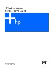
1.1 Comparison of <strong>Sun</strong> <strong>StorEdge</strong> 3510 FCArrays <strong>and</strong> <strong>Sun</strong> <strong>StorEdge</strong> 3511 FC ArraysFIGURE 1-1<strong>Sun</strong> <strong>StorEdge</strong> 3510 <strong>and</strong> 3511 FC Array Front ViewBefore installing <strong>and</strong> configuring your array, please review the key differencesbetween the <strong>Sun</strong> <strong>StorEdge</strong> 3510 FC array <strong>and</strong> the <strong>Sun</strong> <strong>StorEdge</strong> 3511 FC array withSATA, listed in TABLE 1-1.Note – Although the two products are very similar <strong>and</strong> have the same generalfunctionality, the configurations have important differences.TABLE 1-1Comparison of <strong>Sun</strong> <strong>StorEdge</strong> 3510 <strong>and</strong> 3511 FC Array FeaturesApplicationsDisks<strong>Sun</strong> <strong>StorEdge</strong> 3510 FC ArrayBest suited for productionapplications where the superiorfeatures of FC technicalcharacteristics <strong>and</strong> performance is arequirement. This includes the belowonline applications:• Database• Decision Support• Data warehousing• Electronic commerce• Enterprise resource planning• Messaging, file <strong>and</strong> printFibre Channel disks:36, 73, or 146 GB at 10k rpm36 or 73 GB at 15k rpm<strong>Sun</strong> <strong>StorEdge</strong> 3511 FC ArrayBest suited for an inexpensivesecondary storage application wherehigher capacity drives are needed whichare not mission-critical, <strong>and</strong> wherelower performance <strong>and</strong> less than 7/24availability is an option. This includesthe below near-line applications:• Information lifecycle management• Content addressable storage• Backup <strong>and</strong> restore• Secondary SAN storage• Near-line DAS storage• Static reference data storageSATA disks:250 GB at 7200 rpm1-2 <strong>Sun</strong> <strong>StorEdge</strong> <strong>3000</strong> <strong>Family</strong> <strong>Installation</strong>, <strong>Operation</strong>, <strong>and</strong> <strong>Service</strong> <strong>Manual</strong> • May 2004
TABLE 1-1Comparison of <strong>Sun</strong> <strong>StorEdge</strong> 3510 <strong>and</strong> 3511 FC Array Features (Continued)Maximum FC Host Ports perI/O Controller Module<strong>Sun</strong> <strong>StorEdge</strong> 3510 FC Array4(one SFP port each for channels 0, 1,4, <strong>and</strong> 5)<strong>Sun</strong> <strong>StorEdge</strong> 3511 FC Array6(two SFP ports each for channels 1 <strong>and</strong>0; one SFP port each for channels 4 <strong>and</strong>5)Maximum Number ofExpansion Units Connectedto a RAID Array8 5Maximum Number of Disksper Configuration108 (1 RAID array + 8 expansionunits)72 (1 RAID array + 5 expansion units)Maximum Number ofLogical DrivesMaximum Total StorageCapacity8 logical drives 8 logical drives15.75 TB 18.0 TBMaximum Usable StorageCapacity14.0 TB RAID 515.1 TB RAID 014.0 TB RAID 516.0 TB Raid 0JBOD Array Support One JBOD per server Not supported1.1.1 <strong>Sun</strong> <strong>StorEdge</strong> 3510 <strong>and</strong> 3511 FC ArrayConfigurations<strong>Sun</strong> <strong>StorEdge</strong> 3510 <strong>and</strong> 3511 FC arrays can be used in the following configurations:■ Single controller configuration. A RAID array can be configured with a singlecontroller in a non-redundant configuration.■ A RAID array with two controllers. A RAID array can be configured with twocontrollers to provide full redundancy.■ An expansion unit. An expansion unit consists of a chassis with disk drives <strong>and</strong>I/O expansion modules. The expansion unit does not include an I/O controllermodule. The expansion unit connects to <strong>and</strong> is managed by a RAID array■ A Just a Bunch of Disks (JBOD) array. The JBOD array connects to, <strong>and</strong> ismanaged by, a host server. Only the <strong>Sun</strong> <strong>StorEdge</strong> 3510 FC JBOD is supported.See “Using a St<strong>and</strong>alone JBOD Array (<strong>Sun</strong> <strong>StorEdge</strong> 3510 FC Array Only)” onpage B-1 for detailed information about using <strong>Sun</strong> <strong>StorEdge</strong> 3510 FC JBOD arrays.TABLE 1-2 shows the configuration options for <strong>Sun</strong> <strong>StorEdge</strong> 3510 <strong>and</strong> 3511 FC arrays.Chapter 1 Product <strong>and</strong> Architecture Overview 1-3
TABLE 1-2<strong>Sun</strong> <strong>StorEdge</strong> 3510 <strong>and</strong> 3511 FC Array Configuration OptionsInternal RAID controllers Up to 2, with a minimum of 12-Gbit/sec Fibre Channel disks(<strong>Sun</strong> <strong>StorEdge</strong> 3510 FC Array) *1.5-Gbit/sec serial ATA disks(<strong>Sun</strong> <strong>StorEdge</strong> 3511 FC array)FC expansion units †FC JBOD arrays ‡ (<strong>Sun</strong><strong>StorEdge</strong> 3510 FC array only)Connection optionsUp to 12 per array or per expansion unit, with aminimum of 4 plus 1 spareUp to 8 for a <strong>Sun</strong> <strong>StorEdge</strong> 3510 FC array. Up to 5 for a<strong>Sun</strong> <strong>StorEdge</strong> 3511 FC array1• Serial port• Ethernet• Fibre Channel Small Form-Factor Pluggable (SFP)Supported RAID levels 0, 1, 3, 5, 1+0, 3+0, <strong>and</strong> 5+0Redundant field-replaceableunits (FRUs)Configuration management <strong>and</strong>enclosure event reportingoptions §• Power supply <strong>and</strong> fan modules• I/O controller modules <strong>and</strong> I/O expansion modules• I/O expansion modules• Battery board module• Disk drive modules• In-b<strong>and</strong> Fibre Channel ports• Out-of-b<strong>and</strong> 10/100 BASE-T Ethernet port• RS-232 connectivity• Enclosure monitoring by SCSI Enclosure <strong>Service</strong>s(SES)* 1-GHz drives are not supported.† A disk array with no controller. Each expansion unit has two Fibre Channel loops that can provide redundantdata paths back to the RAID array.‡ A disk array with no controller that is connected directly to a host computer, with no RAID array in the loop.Only <strong>Sun</strong> <strong>StorEdge</strong> 3510 support the JBOD configuration.§ The host-based <strong>Sun</strong> <strong>StorEdge</strong> Configuration <strong>Service</strong> software provides a graphical user interface (GUI) <strong>and</strong> additionalevent-reporting capabilities.RAID or JBOD/Expansion Unit Identification on Chassis. A label on the bottom lipof an array chassis, underneath the front bezel, indicates whether it is a JBOD arrayor a RAID array. For instance, “3510 AC JBOD” refers to an alternating-currentversion of a 3510 JBOD array, “3510 DC JBOD” refers to a direct-current version of aJBOD array, <strong>and</strong> “3510 AC RAID” refers to an alternating-current version of a RAIDarray. Similarly, using a UNIX comm<strong>and</strong> such as probe-scsi-all provides similar1-4 <strong>Sun</strong> <strong>StorEdge</strong> <strong>3000</strong> <strong>Family</strong> <strong>Installation</strong>, <strong>Operation</strong>, <strong>and</strong> <strong>Service</strong> <strong>Manual</strong> • May 2004
information, using an “A” designator for RAID arrays <strong>and</strong> a “D” designator fordisks in a JBOD array. For example, “<strong>StorEdge</strong> 3510F D1000” identifies a JBOD arraywith SES firmware version 1000, <strong>and</strong> “<strong>StorEdge</strong> 3510F A1000” identifies a <strong>Sun</strong><strong>StorEdge</strong> 3510 FC RAID array with firmware version 1000.For a list of supported racks <strong>and</strong> cabinets, refer to the release notes for the model ofarray that you are installing. You can find these release notes at:http://www.sun.com/products-n-solutions/hardware/docs/Network_Storage_Solutions/Workgroup/3510orhttp://www.sun.com/products-n-solutions/hardware/docs/Network_Storage_Solutions/Workgroup/3511Reliability, availability, <strong>and</strong> serviceability (RAS) are supported by:■ Redundant components■ Notification of failed components■ Components that are replaceable while the unit is onlineFor information about specifications <strong>and</strong> agency approvals, see “<strong>Sun</strong> <strong>StorEdge</strong> 3510<strong>and</strong> 3511 FC Array Specifications” on page A-1.1.2 Field-Replaceable Units (FRUs)This section describes the FRUs contained in the <strong>Sun</strong> <strong>StorEdge</strong> 3510 <strong>and</strong> 3511 FCArrays.1.2.1 RAID I/O Controller ModulesA dual-controller configuration offers increased reliability <strong>and</strong> availability because iteliminates a single point of failure, the controller. In a dual-controller configuration,if the primary controller fails, the array automatically fails over to the secondcontroller without an interruption of data flow.<strong>Sun</strong> <strong>StorEdge</strong> 3510 <strong>and</strong> 3511 FC array I/O controller modules are hot-serviceable.<strong>Sun</strong> <strong>StorEdge</strong> 3510 FC array RAID controller modules provide six Fibre Channelports. <strong>Sun</strong> <strong>StorEdge</strong> 3511 FC array I/O controller modules provide eight FibreChannel ports. Single- <strong>and</strong> dual-controller models are available, with the dualcontrollerversion supporting active/passive <strong>and</strong> active/active configurations. EachRAID controller is configured with 1 gigabyte (Gbyte) of cache.Chapter 1 Product <strong>and</strong> Architecture Overview 1-5
In the unlikely event of an I/O Controller Module failure, the redundant RAIDcontroller immediately begins servicing all I/O requests. The failure does not affectapplication programs.Each RAID I/O controller module can support up to 1 gigabyte of SynchronousDynamic R<strong>and</strong>om Access Memory (SDRAM) with Error Control Check (ECC)memory. In addition, each controller supports 64 megabytes (Mbyte) of on-boardmemory. Two Application Specific Integrated Circuit (ASIC) controller chips h<strong>and</strong>lethe interconnection between the controller bus, DRAM memory, <strong>and</strong> PeripheralComponent Interconnect (PCI) internal buses. They also h<strong>and</strong>le the interfacebetween the on-board 2 Mbyte flash, 32 Kbyte nonvolatile r<strong>and</strong>om access memory(NVRAM) RS-232 port chip, <strong>and</strong> 10/100 BASE-T Ethernet chip.The RAID I/O controller module is a multifunction board. I/O controller modulesinclude Small Form-Factor Pluggable (SFP) ports, the SES logic, <strong>and</strong> the RAIDcontroller. The SES logic monitors various temperature thresholds, fan speed fromeach fan, voltage status from each power supply, <strong>and</strong> the FRU ID.Each RAID I/O controller module incorporates SES direct-attached Fibre Channelcapability to monitor <strong>and</strong> maintain enclosure environmental information. The SEScontroller chip monitors all internal +12 <strong>and</strong> +5 voltages, various temperaturesensors located throughout the chassis, <strong>and</strong> each fan. The SES also controls the front<strong>and</strong> back panel LEDs <strong>and</strong> the audible alarm. Both the RAID chassis <strong>and</strong> theexpansion chassis support dual SES failover capabilities for fully redundant eventmonitoring.1.2.2 I/O Expansion ModulesThe hot-serviceable I/O expansion modules provide four (<strong>Sun</strong> <strong>StorEdge</strong> 3510 FCarray) or eight (<strong>Sun</strong> <strong>StorEdge</strong> 3511 FC array) SFP ports but do not have batterymodules or controllers. I/O expansion modules are used with I/O ControllerModules in non-redundant <strong>Sun</strong> <strong>StorEdge</strong> 3510 <strong>and</strong> 3511 FC arrays, <strong>and</strong> in expansionunits <strong>and</strong> JBODs.1.2.3 Disk DrivesEach disk drive is mounted in its own sled assembly. Each sled assembly has EMIshielding, an insertion <strong>and</strong> locking mechanism, <strong>and</strong> a compression spring formaximum shock <strong>and</strong> vibration protection.1-6 <strong>Sun</strong> <strong>StorEdge</strong> <strong>3000</strong> <strong>Family</strong> <strong>Installation</strong>, <strong>Operation</strong>, <strong>and</strong> <strong>Service</strong> <strong>Manual</strong> • May 2004
Each disk drive is slot-independent, meaning that once a logical drive has beeninitialized, the system can be shut down <strong>and</strong> the drives can be removed <strong>and</strong>replaced in any order. In addition, disk drives are field-upgradeable to larger driveswithout interruption of service to user applications. The drive firmware is also fieldupgradeable,but the firmware upgrade procedure requires interruption of service.In the event of a single disk drive failure, with the exception of RAID 0, the systemcontinues to service all I/O requests. Either mirrored data or parity data is used torebuild data from the failed drive to a spare drive, assuming one is assigned. If aspare is not assigned, you have to manually rebuild the array.In the unlikely event that multiple drive failures occur within the same logical drive,data that has not been replicated or backed up might be lost. This is an inherentlimitation of all RAID subsystems <strong>and</strong> could affect application programs.An air management sled FRU is available for use when you remove a disk drive <strong>and</strong>do not replace it. Insert an air management sled into the empty slot to maintainoptimum airflow through the chassis.1.2.3.1 <strong>Sun</strong> <strong>StorEdge</strong> 3510 FC Array Disk DrivesThe drives can be ordered in 36-GB, 73-GB, <strong>and</strong> 146-GB sizes. Thirty-six-gigabytedrives have a rotation speed of 15,000 RPM, while 73-GB drives <strong>and</strong> 146-GB driveshave a rotation speed of 10,000 RPM.1.2.3.2 <strong>Sun</strong> <strong>StorEdge</strong> 3511 FC Array Disk DrivesThe disk drives incorporate Serial ATA (SATA) technology. They are optimized forcapacity, but have performance levels approaching Fibre Channel performancelevels. The drives are 250-GB drives <strong>and</strong> have a rotation speed of 7200 RPM.1.2.4 Battery ModuleThe battery module is designed to provide power to system cache for 72 hours in theevent of a power failure. When power is reapplied, the cache is purged to disk. Thebattery module is a hot-swappable FRU that is mounted on the I/O board withguide rails <strong>and</strong> a transition board. It also contains the EIA-232 <strong>and</strong> DB9 serialinterface (COM) ports.Chapter 1 Product <strong>and</strong> Architecture Overview 1-7
1.2.5 Power <strong>and</strong> Fan ModulesNote – The <strong>Sun</strong> <strong>StorEdge</strong> 3511 FC array can only be ordered in an AC configuration.However, DC power supplies can be ordered in an x-option kit, <strong>and</strong> the <strong>Sun</strong><strong>StorEdge</strong> 3511 FC array’s can be reconfigured using the DC power supplies. Refer tothe <strong>Sun</strong> <strong>StorEdge</strong> <strong>3000</strong> <strong>Family</strong> FRU <strong>Installation</strong> Guide.Each array contains redundant (two) power <strong>and</strong> fan modules. Each module containsa 420-watt power supply <strong>and</strong> two radial 52 cubic feet per minute (CFM) fans. Powermodule autoranging capabilities range:■ AC Power Supply. From 90 Volts Alternating Current (VAC) to 264 VAC.■DC Power Supply. From -36 Volts Direct Current (VDC) to -72 VDC.A single power <strong>and</strong> fan module can sustain an array.1.3 InteroperabilityThe array is designed for heterogeneous operation <strong>and</strong> supports the followingoperating environments:■ Solaris operating environment versions 8 <strong>and</strong> 9■ <strong>Sun</strong> Linux 5.0 on the <strong>Sun</strong> LX50 server■ Red Hat Linux distribution■ Windows NT 4.0 <strong>and</strong> Windows 2000 server■ IBM AIX Terminal Menu■ HP-UXNote – For information about supported versions of these operating environments,refer to the release notes for your array.The array does not require any host-based software for configuration, management,<strong>and</strong> monitoring, which can be h<strong>and</strong>led through the built-in firmware application.The console window can be accessed via the DB9 communications (COM) port usingthe tip comm<strong>and</strong>, or via the Ethernet port using the telnet comm<strong>and</strong>.1-8 <strong>Sun</strong> <strong>StorEdge</strong> <strong>3000</strong> <strong>Family</strong> <strong>Installation</strong>, <strong>Operation</strong>, <strong>and</strong> <strong>Service</strong> <strong>Manual</strong> • May 2004
1.4 Fibre Channel Technology OverviewAs a device protocol capable of high data transfer rates, Fibre Channel simplifiesdata bus sharing <strong>and</strong> supports not only greater speed than SCSI, but also moredevices on the same bus. Fibre Channel can be used over both copper wire <strong>and</strong>optical cable. It can be used for concurrent communications among multipleworkstations, servers, storage systems, <strong>and</strong> other peripherals using SCSI <strong>and</strong> IPprotocols. When a Fibre Channel hub or fabric switch is employed, it providesflexible topologies for interconnections.1.4.1 FC ProtocolsTwo common protocols are used to connect Fibre Channel (FC) nodes together:■ Point-to-point. The point-to-point protocol is straightforward, doing little morethan establishing a permanent communication link between two ports.■ Arbitrated loop. The arbitrated loop protocol creates a simple network featuringdistributed (arbitrated) management between two or more ports using a circular(loop) data path. Arbitrated loops can support more nodes than point-to-pointconnections.The <strong>Sun</strong> <strong>StorEdge</strong> 3510 <strong>and</strong> 3511 FC arrays support both point-to-point <strong>and</strong>arbitrated loop protocols. You select the protocol you prefer by setting the desiredFibre Channel Connection Option in the Configuration parameters of the firmwareapplication (see “Summary of Array Configuration” on page 5-6).1.4.2 FC TopologiesThe presence or lack of switches establishes the topology of an FC environment. In adirect attached storage (DAS) topology, servers connect straight to arrays withoutswitches. In a storage area network (SAN) topology, servers <strong>and</strong> arrays connect to anFC network created <strong>and</strong> managed by switches.Refer to the <strong>Sun</strong> <strong>StorEdge</strong> <strong>3000</strong> <strong>Family</strong> Best Practices <strong>Manual</strong> for your array to seeinformation about optimal configurations for site requirements.Chapter 1 Product <strong>and</strong> Architecture Overview 1-9
1.4.3 Fibre Hubs <strong>and</strong> SwitchesA storage network built on a Fibre Channel architecture might employ several of thefollowing components: Fibre Channel host adapters, hubs, fabric switches, <strong>and</strong> fibreto-SCSIbridges.■ Fibre hubs. An arbitrated loop hub is a wiring concentrator. “Arbitrated” meansthat all nodes communicating over this fibre loop are sharing a 100 megabits persecond (Mbps) segment. Whenever more devices are added to a single segment,the b<strong>and</strong>width available to each node is further divided.A loop configuration allows different devices in the loop to be configured in atoken ring style. With a fibre hub, a fibre loop can be rearranged in a star-likeconfiguration because the hub itself contains port bypass circuitry that forms aninternal loop inside. Bypass circuits can automatically reconfigure the loop once adevice is removed or added without disrupting the physical connection to otherdevices.■Fabric switches. A fabric switch functions as a routing engine, which activelydirects data transfers from source to destination <strong>and</strong> arbitrates every connection.B<strong>and</strong>width per node via a fabric switch remains constant when more nodes areadded, <strong>and</strong> a node on a switch port uses an up-to-100-Mbps data path to send orreceive data.1.4.4 Data AvailabilityData availability is one of the major requirements for today’s mission-criticalapplications. Highest availability can be accomplished with the followingfunctionality:■ Hot-plug capabilities. With proper hardware <strong>and</strong> software configuration in dualcontrollermode, a failed controller can be replaced online while the existingcontroller is actively serving I/O.■ Dual-loop configurations. Dual loop provides path redundancy <strong>and</strong> greaterthroughput.■ Controller communications over Fibre Channel. Selectable either throughdedicated loops or all drive loops. This allows a more flexible configuration ofredundant controllers.1-10 <strong>Sun</strong> <strong>StorEdge</strong> <strong>3000</strong> <strong>Family</strong> <strong>Installation</strong>, <strong>Operation</strong>, <strong>and</strong> <strong>Service</strong> <strong>Manual</strong> • May 2004
1.4.5 ScalabilityThe Fibre Channel architecture brings scalability <strong>and</strong> easier upgrades to storage.Storage expansion can be as easy as cascading another expansion unit to aconfigured RAID array without powering down the running system. The maximumnumber of expansion units supported by a single <strong>Sun</strong> <strong>StorEdge</strong> Fibre Channel arrayis:■ <strong>Sun</strong> <strong>StorEdge</strong> 3510 FC Array. Up to 8 expansion units.■ <strong>Sun</strong> <strong>StorEdge</strong> 3511 FC Array. Up to 5 expansion units.Note – Do not mix the <strong>Sun</strong> <strong>StorEdge</strong> 3510 FC expansion units with <strong>Sun</strong> <strong>StorEdge</strong>3511 FC arrays or vice versa. Connect only <strong>Sun</strong> <strong>StorEdge</strong> 3510 FC expansion units to<strong>Sun</strong> <strong>StorEdge</strong> 3510 FC arrays, <strong>and</strong> connect only <strong>Sun</strong> <strong>StorEdge</strong> 3511 FC expansionunits to <strong>Sun</strong> <strong>StorEdge</strong> 3511 FC arrays.Up to 125 devices can be configured in a single FC loop. By default, the arrayprovides two drive loops <strong>and</strong> four host loops, <strong>and</strong> operates in Fibre Channel-Arbitrated Loop (FC-AL) <strong>and</strong> fabric topologies.1.5 Fibre Channel ArchitectureEach RAID array has six Fibre Channels with the following defaults:■ Channels 0, 1, 4, <strong>and</strong> 5 are host channels connected to servers. Any <strong>Sun</strong> <strong>StorEdge</strong>3510 FC array host channels can be reassigned as drive channels to connect toexpansion units. <strong>Sun</strong> <strong>StorEdge</strong> 3511 FC array channels 3 <strong>and</strong> 4 can also bereassigned as drive channels.■ Channels 2 <strong>and</strong> 3 are dedicated drive channels that connect the internal 12-diskdrives in the RAID chassis, <strong>and</strong> can also be used to add expansion chassis to theconfiguration.■ FC-AL is the default mode. Point-to-point is also available.The <strong>Sun</strong> <strong>StorEdge</strong> 3510 expansion unit has a total of four FC-AL ports. The <strong>Sun</strong><strong>StorEdge</strong> 3511 expansion unit has a total of eight FC-AL ports.Note – Throughout this manual, Fibre Channel-Arbitrated Loops are referred tosimply as loops.See chapter 4 for detailed host <strong>and</strong> drive channel information.Chapter 1 Product <strong>and</strong> Architecture Overview 1-11
1.5.1 Redundant Configuration ConsiderationsThis section provides information about setting up redundant configurations forincreased reliability. For more detailed information about configurationrequirements, refer “First-Time Configuration” on page 6-1 <strong>and</strong> to the <strong>Sun</strong> <strong>StorEdge</strong><strong>3000</strong> <strong>Family</strong> Best Practices <strong>Manual</strong>.1.5.1.1 Host Bus AdaptersFibre Channel is widely applied to storage configurations with topologies that aimto avoid loss of data because of component failure. As a rule, the connectionsbetween source <strong>and</strong> target should be configured in redundant pairs.The recommended host-side connection consists of two or more host bus adapters(HBAs). Each HBA is used to configure a Fibre Channel loop between the hostcomputer <strong>and</strong> the array. In active-to-active redundant controller mode, the primaryloop serves the I/O traffic directed to the primary controller, <strong>and</strong> its pair loop servesthe I/O traffic to the secondary controller. The host-side management softwaredirects I/O traffic to the pair loop if one of the redundant loops fails.1.5.1.2 Active-to-Active Redundant ControllerSince each fibre interface supports only a single loop ID, two HBAs are necessary foractive-to-active redundant controller operation. Using two HBAs in each serverensures continued operation even when one data path fails.In active-to-active mode, the connection to each host adapter should be considered adata path connecting the host to either the primary or the secondary controller. Oneadapter should be configured to serve the primary controller <strong>and</strong> the other adapterto serve the secondary controller. Each target ID on the host channels should beassigned either a primary ID or a secondary ID. If one controller fails, the remainingcontroller can inherit the ID from its counterpart <strong>and</strong> activate the st<strong>and</strong>by channel toserve host I/O.1.5.1.3 Host Redundant PathsThe controller passively supports redundant fibre loops on the host side, providedthat the host has implemented software support for this feature.In the unlikely event of controller failure, the st<strong>and</strong>by channels on the remainingcontroller become an I/O route serving the host I/O originally directed to the failedchannel on its pair of controllers. Moreover, application failover software should berunning on the host computer to control the transfer of I/O from one HBA toanother in case either data path fails.1-12 <strong>Sun</strong> <strong>StorEdge</strong> <strong>3000</strong> <strong>Family</strong> <strong>Installation</strong>, <strong>Operation</strong>, <strong>and</strong> <strong>Service</strong> <strong>Manual</strong> • May 2004
1.6 Additional Software ToolsThe following additional software tools are available on the <strong>Sun</strong> <strong>StorEdge</strong> <strong>3000</strong><strong>Family</strong> Professional Storage Manager CD, provided with your array:■ <strong>Sun</strong> <strong>StorEdge</strong> Configuration <strong>Service</strong>, a management <strong>and</strong> monitoring program■ <strong>Sun</strong> <strong>StorEdge</strong> Diagnostic Reporter software, a monitoring utility■ <strong>Sun</strong> <strong>StorEdge</strong> CLI, a comm<strong>and</strong>-line utility to monitor <strong>and</strong> manage the array.Refer to the <strong>Sun</strong> <strong>StorEdge</strong> <strong>3000</strong> <strong>Family</strong> Software <strong>Installation</strong> Guide for information aboutinstalling these tools.Array-related user guides with configuration procedures for these tools are providedon:■ <strong>Sun</strong> <strong>StorEdge</strong> 3510 FC Array. The <strong>Sun</strong> <strong>StorEdge</strong> <strong>3000</strong> <strong>Family</strong> Documentation CD.■<strong>Sun</strong> <strong>StorEdge</strong> 3511 FC Array. The <strong>Sun</strong> <strong>StorEdge</strong> 3511 FC Array DocumentationCD.For other supported software tools, refer to the release notes at the followinglocations.■ http://www.sun.com/products-n-solutions/hardware/docs/Network_Storage_Solutions/Workgroup/3510or■ http://www.sun.com/products-n-solutions/hardware/docs/Network_Storage_Solutions/Workgroup/3511Chapter 1 Product <strong>and</strong> Architecture Overview 1-13
1-14 <strong>Sun</strong> <strong>StorEdge</strong> <strong>3000</strong> <strong>Family</strong> <strong>Installation</strong>, <strong>Operation</strong>, <strong>and</strong> <strong>Service</strong> <strong>Manual</strong> • May 2004
CHAPTER 2Site PlanningThis chapter outlines the site-planning requirements <strong>and</strong> basic safety requirementsfor the installation <strong>and</strong> use of the <strong>Sun</strong> <strong>StorEdge</strong> 3510 <strong>and</strong> 3511 FC arrays. Complete apreinstallation worksheet <strong>and</strong> prepare the site for installation according to theworksheet details <strong>and</strong> the specified site-planning requirements.Review the details of this chapter before installing a <strong>Sun</strong> <strong>StorEdge</strong> 3510 or 3511 FCarray. Topics covered in this chapter are:■ “Customer Obligations” on page 2-2■ “Safety Precautions” on page 2-2■ “Environmental Requirements” on page 2-3■ “Electrical <strong>and</strong> Power Specifications” on page 2-4■ “Physical Specifications” on page 2-5■ “Layout Map” on page 2-5■ “Console <strong>and</strong> Other Requirements” on page 2-7■ “Preinstallation Worksheet” on page 2-7Note – The release notes for your array list the supported operating environments,host platforms, software, <strong>and</strong> qualified cabinets.2-1
2.1 Customer ObligationsThe customer is obliged to inform <strong>Sun</strong> Microsystems, Inc. of any <strong>and</strong> all ordinances<strong>and</strong> regulations that would affect installation.Caution – When selecting an installation site for the <strong>Sun</strong> <strong>StorEdge</strong> 3510 or 3511 FCarray, choose a location that avoids excessive heat, direct sunlight, dust, or chemicalexposure. Such exposure greatly reduces the product’s longevity <strong>and</strong> might voidyour warranty.The customer is responsible for meeting all government codes <strong>and</strong> regulationsconcerning facilities. The customer is also responsible for compliance with thefollowing requirements:■ Meeting all local, national, <strong>and</strong> international codes covered in “<strong>Sun</strong> <strong>StorEdge</strong> 3510<strong>and</strong> 3511 FC Array Specifications” on page A-1. The subjects covered include fire<strong>and</strong> safety, building, <strong>and</strong> electrical codes.■ Documenting <strong>and</strong> informing <strong>Sun</strong> Microsystems, Inc. of any deviations from “<strong>Sun</strong><strong>StorEdge</strong> 3510 <strong>and</strong> 3511 FC Array Specifications” on page A-1.2.2 Safety PrecautionsFor your protection, observe the following safety precautions when setting up yourequipment:■ Follow all safety precautions <strong>and</strong> requirements specified in the <strong>Sun</strong> <strong>StorEdge</strong> <strong>3000</strong><strong>Family</strong> Safety, Regulatory, <strong>and</strong> Compliance <strong>Manual</strong>.■ A fully loaded array weighs over 59 pounds. Use two people to lift the array toavoid injury.■ Follow all cautions <strong>and</strong> instructions marked on the equipment.■ Ensure that the voltage <strong>and</strong> frequency of your power source match the voltage<strong>and</strong> frequency inscribed on the equipment’s electrical rating label.■ Never push objects of any kind through openings in the equipment. Dangerousvoltages might be present. Conductive foreign objects could produce a shortcircuit that could cause fire, electric shock, or damage to your equipment.2-2 <strong>Sun</strong> <strong>StorEdge</strong> <strong>3000</strong> <strong>Family</strong> <strong>Installation</strong>, <strong>Operation</strong>, <strong>and</strong> <strong>Service</strong> <strong>Manual</strong> • May 2004
■■■■To reduce the risk of electric shock, do not plug <strong>Sun</strong> products into any other typeof power system. <strong>Sun</strong> products are designed to work with single-phase powersystems having a grounded neutral conductor. Contact your facilities manager ora qualified electrician if you are not sure what type of power is supplied to yourbuilding.Your <strong>Sun</strong> product is shipped with a grounding-type (three-wire) power cord. Toreduce the risk of electric shock, always plug the cord into a grounded poweroutlet.Do not use household extension cords with your <strong>Sun</strong> product. Not all powercords have the same current ratings. Household extension cords do not haveoverload protection <strong>and</strong> are not meant for use with computer systems.Do not block or cover the openings of your <strong>Sun</strong> product. Never place a <strong>Sun</strong>product near a radiator or heat register. Failure to follow these guidelines cancause overheating <strong>and</strong> affect the reliability of your <strong>Sun</strong> product.2.3 Environmental RequirementsTABLE 2-1Environmental SpecificationsOperatingNonoperatingAltitude To <strong>3000</strong> meters (9000 feet) To 12,000 meters (36,000 feet)HumidityTemperatureSt<strong>and</strong>aloneRack10% to 90% RH at 27 degrees Cmax wet bulb (noncondensing)5 degrees C to 40 degrees C5 degrees C to 35 degrees C93% RH, 38 degrees C max wetbulb temperature (noncondensing)-40 degrees C to +65 degrees C-40 degrees C to +65 degrees C2.3.1 Electromagnetic Compatibility (EMC)The following is required for all installations:■ All AC mains <strong>and</strong> supply conductors to power distribution boxes for both therack-mounted array <strong>and</strong> the desktop array must be enclosed in a metal conduit orraceway when specified by local, national, or other applicable government codes<strong>and</strong> regulations.■ The supply conductors <strong>and</strong> power distribution boxes (or equivalent metalenclosure) must be grounded at both ends.Chapter 2 Site Planning 2-3
■■The supplied arrays require voltages within minimum fluctuation.The facilities voltage supplied by the customer must maintain a voltage with notmore than (+/–) 5 percent fluctuation. The customer facilities must providesuitable surge protection.2.4 Electrical <strong>and</strong> Power Specifications<strong>Sun</strong> <strong>StorEdge</strong> 3510 <strong>and</strong> 3511 FC arrays require two independent power sources. Eacharray has two power supply <strong>and</strong> fan modules for redundancy.Each AC array requires two 115 VAC/15A or two 240 VAC service outlets. All ACpower supplies are autoranging <strong>and</strong> are automatically configured to a range of 90-264 VAC <strong>and</strong> 47-63 Hz. There is no need to make special adjustments.Each DC array requires two –48 VDC service outlets <strong>and</strong> has an input voltage rangeof –36 VDC to –72 VDC.Note – To ensure power redundancy, be sure to connect the two array powermodules to two separate circuits (for example, one commercial circuit <strong>and</strong> one UPS).TABLE 2-2Power SpecificationsAC powerInput currentPower-supply output voltageDC powerVoltage <strong>and</strong> frequency 90 to 264 VAC, 47 to 63 Hz5A max+5 VDC <strong>and</strong> +12 VDC–48V DC (–36 VDC to –72 VDC)2-4 <strong>Sun</strong> <strong>StorEdge</strong> <strong>3000</strong> <strong>Family</strong> <strong>Installation</strong>, <strong>Operation</strong>, <strong>and</strong> <strong>Service</strong> <strong>Manual</strong> • May 2004
2.5 Physical SpecificationsUse the physical specifications in TABLE 2-3 to plan the location of your array.TABLE 2-3CategoryDimensionsPhysical SpecificationsDescription2U (3.45 inches / 8.76 cm) height20 inches / 50.8 cm chassis depth17.5 inches / 44.6 cm width (19 inches / 48.26 cm with ears)<strong>Installation</strong> clearancesCooling clearancesFor FRU component removal <strong>and</strong> replacement, 15-inches (37 cm)is required front <strong>and</strong> back.6 inches (15 cm) is required front <strong>and</strong> back. No cooling clearance isrequired on the sides or the top <strong>and</strong> bottom of the array.2.6 Layout MapIt is helpful to create a sketch or layout map to indicate the exact location of thearray as well as the location of the hosts, console, <strong>and</strong> Ethernet connections that willbe connected to it.As you lay out the components, consider the cable lengths that will be used.2.6.1 Rack PlacementFollow these guidelines when preparing a rackmount placement for your system:■ Ensure that the floor surface is level.■ Leave enough space in front of the rack to access components for servicing.■ Leave enough space in back of the rack to access components for servicing.■ Keep power <strong>and</strong> interface cables clear of foot traffic. Route cables inside walls,under the floor, through the ceiling, or in protective channels or raceways.■ Route interface cables away from motors <strong>and</strong> other sources of magnetic or radiofrequency interference.■ Stay within the cable length limitations.Chapter 2 Site Planning 2-5
■Provide two separate power sources for the array. These power sources must beindependent of each other, <strong>and</strong> each must be controlled by a separate circuitbreaker at the power distribution point.2.6.2 Tabletop Placement<strong>Sun</strong> <strong>StorEdge</strong> 3510 <strong>and</strong> 3511 FC arrays can be positioned on a desk or a table. Followthese guidelines when preparing a tabletop placement for your system:■ Choose a desk or a table that can support 60 pounds for each fully configuredarray you plan to place on it.■ Do not place the arrays on the edge of the table. Set the array so that at least 50percent of the array is inside the table or desk leg support area. Failure to do thismight cause the table to tip over.■ Leave enough space in front <strong>and</strong> in back of the array to access components forservicing. To remove the components requires a clearance of 15 inches (37 cm) infront <strong>and</strong> in back of the array.■ Provide a minimum space of 6 inches (15 cm) in front <strong>and</strong> in back of the array foradequate airflow.■ Keep power <strong>and</strong> interface cables clear of foot traffic. Route cables inside walls,under the floor, through the ceiling, or in protective channels or raceways.■ Route interface cables away from motors <strong>and</strong> other sources of magnetic or radiofrequency interference.■ Stay within the cable length limitations.■ Ensure that the operating environment for the array does not exceed thespecifications.■ Use two people to lift the array to avoid injury. The array can weigh over 60pounds.■ Do not place the array in a vertical position. Place the array horizontally.■ If you are installing more than one array, you can stack up to five arrays on top ofeach other. Do not stack more than five arrays together.■ Provide two separate power sources for the array. These power sources must beindependent of each other, <strong>and</strong> each must be controlled by a separate circuitbreaker at the power distribution point.2-6 <strong>Sun</strong> <strong>StorEdge</strong> <strong>3000</strong> <strong>Family</strong> <strong>Installation</strong>, <strong>Operation</strong>, <strong>and</strong> <strong>Service</strong> <strong>Manual</strong> • May 2004
2.7 Console <strong>and</strong> Other RequirementsA console with at least one serial port connection is necessary for installation <strong>and</strong>configuration of your <strong>Sun</strong> <strong>StorEdge</strong> 3510 or 3511 FC array. Once you have configuredyour array with an IP address, an Ethernet port can also be useful for configuringthe array.Refer to the following preinstallation worksheet for additional preparation details.2.8 Preinstallation WorksheetBefore ordering a <strong>Sun</strong> <strong>StorEdge</strong> 3510 or 3511 FC array, complete the preinstallationworksheet <strong>and</strong> then prepare the site for installation according to the site-planningrequirements.Note – If you are connecting to several hosts or fabric switches, make as manycopies of TABLE 2-5 as you need <strong>and</strong> label them appropriately.You are responsible for ensuring that the site consistently conforms to all stipulatedst<strong>and</strong>ards <strong>and</strong> that necessary peripherals are made available to the engineer duringinstallation.Review the details of your specific survey before installing your <strong>Sun</strong> <strong>StorEdge</strong> 3510or 3511 FC array.If necessary, attach or sketch a network diagram to the survey.Chapter 2 Site Planning 2-7
TABLE 2-4Preinstallation WorksheetRackmountingCustomers must ensure that the appropriate service outlets areavailable for installation. Requirements vary.Will the <strong>Sun</strong> <strong>StorEdge</strong> 3510 or 3511 Array be rackmounted? Yes / No• Is the rack supplied by <strong>Sun</strong> Microsystems, Inc.? Yes / No• If yes, include <strong>Sun</strong> model number: ____• If not, make/model: _____________________ /_____________________Does the rack mount:• Front <strong>and</strong> back? If so, depth? ______• Center/Telco? ______What cable lengths are required? _________________Are there any power strips or power sequencers in the rack? Yes / NoAre they supplied by <strong>Sun</strong> Microsystems, Inc.? Yes / No If yes, partnumber: ___________If not, quantity of plugs/outlets required: __________ / __________IP addressArray IP address: ______.______.______.______Array network mask: ______.______.______.______Cabling Fiber-optic cable lengths to connect to hosts: _______________2-8 <strong>Sun</strong> <strong>StorEdge</strong> <strong>3000</strong> <strong>Family</strong> <strong>Installation</strong>, <strong>Operation</strong>, <strong>and</strong> <strong>Service</strong> <strong>Manual</strong> • May 2004
TABLE 2-5Host <strong>and</strong> Fabric Switch Connectivity SummarizedHost or Fabric Switch Connectivity - Host or Fabric Switch #1Host or fabric switch name: _____________________________________Host or fabric switch make/model: ________________________________HBA connector types: _____________________________Cable distance from the array to the host(s): ___________Operating environment: ________________________________Patches installed: ________________________________IP addresses:• Network ____________________• Host or switch _______________Host or Fabric Switch Connectivity - Host or Fabric Switch #2Host or fabric switch name: _____________________________________Host or fabric switch make/model: ________________________________HBA connector types: _____________________________Cable distance from the array to the host(s): ___________Operating environment: ________________________________Patches installed: ________________________________IP addresses:• Network ____________________• Host or switch _______________Chapter 2 Site Planning 2-9
2-10 <strong>Sun</strong> <strong>StorEdge</strong> <strong>3000</strong> <strong>Family</strong> <strong>Installation</strong>, <strong>Operation</strong>, <strong>and</strong> <strong>Service</strong> <strong>Manual</strong> • May 2004
CHAPTER 3Unpacking Your FC ArrayThis chapter describes the procedure for unpacking your <strong>Sun</strong> <strong>StorEdge</strong> 3510 or 3511FC array package. The following topics are covered in this chapter:■ “Opening Your Package” on page 3-2■ “Checking the Package Contents” on page 3-3■ “Customer-Provided Cables” on page 3-5■ “Mounting Your Array in a Rack or Cabinet” on page 3-5■ “Converting a JBOD to a RAID Array” on page 3-63-1
3.1 Opening Your PackageFollow these guidelines for unpacking the equipment.Caution – To avoid personal injury or damage to the equipment during installation,always use two people to remove the unit from its container. This unit weighsapproximately 60 pounds.1. Select a suitable area for unpacking.2. Store all packing material <strong>and</strong> boxes for possible equipment returns.3. Check the contents sheet in your product package.The contents sheet summarizes the st<strong>and</strong>ard contents for your product. See“Checking the Package Contents” on page 3-3 for more information.4. Compare the packing slip <strong>and</strong> the list of parts with the items you received.If the list of parts on your packing slip does not match the items you received, or anyitems appear damaged, immediately notify your carrier agent <strong>and</strong> the supplier whoprepared your shipment.5. Carefully examine the cables provided in the package.If any cable appears to be damaged, contact the technical service department for animmediate replacement.6. Check the list of “Customer-Provided Cables” on page 3-5.These are required to complete your installation.Note – You must purchase or provide fiber-optic cables for connecting <strong>Sun</strong> <strong>StorEdge</strong>3510 <strong>and</strong> 3511 FC arrays to host servers.3-2 <strong>Sun</strong> <strong>StorEdge</strong> <strong>3000</strong> <strong>Family</strong> <strong>Installation</strong>, <strong>Operation</strong>, <strong>and</strong> <strong>Service</strong> <strong>Manual</strong> • May 2004
3.2 Checking the Package ContentsInspect your <strong>Sun</strong> <strong>StorEdge</strong> 3510 or 3511 FC array packages for st<strong>and</strong>ard items as wellas purchased options before you begin installation. If any parts are missing ordamaged, contact your sales representative immediately.3.2.1 St<strong>and</strong>ard <strong>Sun</strong> <strong>StorEdge</strong> Fibre Channel ArrayPackageQuantityItem1 One or more of the following arrays:• <strong>Sun</strong> <strong>StorEdge</strong> 3510 or 3511 FC Array with single controller• <strong>Sun</strong> <strong>StorEdge</strong> 3510 or 3511 FC Array with dual controllers• <strong>Sun</strong> <strong>StorEdge</strong> 3510 or 3511 JBOD/Expansion Unit1 • Contents Sheet for your array• <strong>Sun</strong> <strong>StorEdge</strong> <strong>3000</strong> <strong>Family</strong> Quick <strong>Installation</strong> Guide• To download <strong>and</strong> print the latest release notes, go to one of the following locations:http://www.sun.com/products-n-solutions/hardware/docs/Network_Storage_Solutions/Workgroup/3510orhttp://www.sun.com/products-n-solutions/hardware/docs/Network_Storage_Solutions/Workgroup/35112 CDs in a CD set; one CD for software <strong>and</strong> one CD for user documentation1 Serial null modem cable1 or 2 25-foot (7.5m) CAT5 Ethernet cable (one per controller)1 Cable adapter, DB9-to-DB252 DC power cables if you ordered a DC-powered array2 AC cord locks in a plastic bag if you ordered an AC-powered array1 AC cable country kit if the array is AC-powered2 Front bezel keys in a plastic bag, to secure the front bezel onto the chassisVariousPurchased options. These options are ordered at the time of purchase <strong>and</strong> are integrated into oradded to the unit prior to delivery.Chapter 3 Unpacking Your FC Array 3-3
3.2.2 Field-Replaceable UnitsCheck that you received all field-replaceable units (FRUs) ordered with your <strong>Sun</strong><strong>StorEdge</strong> 3510 or 3511 FC array. For additional FRUs, consult your salesrepresentative. For instructions on how to install or replace FRUS, review thefollowing manuals located on the product web site or on your documentation CD:■ <strong>Sun</strong> <strong>StorEdge</strong> <strong>3000</strong> <strong>Family</strong> Rack <strong>Installation</strong> Guide for 2U Arrays■ <strong>Sun</strong> <strong>StorEdge</strong> <strong>3000</strong> <strong>Family</strong> FRU <strong>Installation</strong> GuideAll FRUs are hot-swappable except the I/O controller <strong>and</strong> I/O expansion modules,which are hot-serviceable. Hot-serviceable means that the module can be replacedwhile the array <strong>and</strong> hosts are powered up but the connected hosts must be inactive.TABLE 3-1List of Available <strong>Sun</strong> <strong>StorEdge</strong> 3510 FC Array FRUsFRU Model NumberDescriptionF370-5535-01BOX, 2U, FC, Chassis + Backplane (RAID/JBOD)F370-5545-01BATTERY, FC, 2UF370-5540-01CABLE, FC, 1.5 FT, EXPANSIONF370-5537-01I/O w/SES & RAID CONT FC, 1 GB MEMORY, BATTERY, 2UF370-5538-01I/O w/SES, JBOD FC, 2UF370-5398-01AC PWR SUPPLY/FAN MOD, 2UXTA-3310-DC-KitDC PWR SUPPLY/FAN MOD, 2UXTA-3510-36GB-15K DRIVE MOD, 36 GB FC, 15KRPMXTA-3510-73GB-10K DRIVE MOD, 73 GB FC, 10KRPMXTA-3510-146GB-10K DRIVE MOD, 146 GB FC, 10KRPMXTA-3510-Ctrl-1G I/O w/SES & RAID CONT FC, 1 GB MEMORY, BATTERY, 2UXTA-<strong>3000</strong>-AMBSAIR MANAGEMENT SLEDXTA-3310-RK-19S RACK KIT, 2U, 19" CABINET 22”-28”XTA-3310-RK-19L RACK KIT, 2U, 19" CABINET 28”-36”XTA-3310-RK-19C RACK KIT, 2U, 19" CABINET TELCO CENTER MNTXTA-3310-RK-19F RACK KIT, 2U, 19" CABINET TELCO FRONT MNTXSFP-LW-2GBSFP, 2G,LW 1310NM, FC, TRANSXSFP-SW-2GBSFP, 2G, SW 850NM, FC, TRANS3-4 <strong>Sun</strong> <strong>StorEdge</strong> <strong>3000</strong> <strong>Family</strong> <strong>Installation</strong>, <strong>Operation</strong>, <strong>and</strong> <strong>Service</strong> <strong>Manual</strong> • May 2004
TABLE 3-2List of Available <strong>Sun</strong> <strong>StorEdge</strong> 3511 FC Array FRUsFRU Model NumberDescriptionF370-6775-01BOX, 2U, SATA, Chassis + Backplane (RAID/JBOD)F370-6773-01I/O-RAID CONT SATA, 1GB, BAT, 2UF370-5540-01CABLE, FC, 1.5 FT, EXPANSIONF370-5545-01BATTERY, SATA, 2UF370-6774-01I/O JBOD SATA, 2UF370-6776-01AC PWR SUPPLY/FAN MOD, 2UF370-6798-01DC PWR SUPPLY/FAN MOD, 2UF540-6180-01DRIVE MOD, 250 GB SATA, 7200 RPMF370-5537-01I/O w/SES & RAID CONT FC, 1 GB MEMORY, BATTERY, 2UXTA-<strong>3000</strong>-AMBSAIR MANAGEMENT SLEDXTA-3310-RK-19S RACK KIT, 2U, 19" CABINET 22”-28”XTA-3310-RK-19L RACK KIT, 2U, 19" CABINET 28”-36”XTA-3310-RK-19C RACK KIT, 2U, 19" CABINET TELCO CENTER MNTXTA-3310-RK-19F RACK KIT, 2U, 19" CABINET TELCO FRONT MNT3.3 Customer-Provided CablesCustomers must provide a minimum of one fiber-optic cable per host to connect ahost to a RAID array. Two fiber-optic cables are required for a redundant pathconfiguration.To obtain qualified cables, consult your <strong>Sun</strong> sales representative.3.4 Mounting Your Array in a Rack orCabinetRefer to <strong>Sun</strong> <strong>StorEdge</strong> <strong>3000</strong> <strong>Family</strong> Rack <strong>Installation</strong> Guide for instructions on how toinstall <strong>and</strong> prepare a rack or cabinet for mounting your array.Chapter 3 Unpacking Your FC Array 3-5
3.5 Converting a JBOD to a RAID ArrayIf you want to convert a JBOD into a RAID array, refer to the <strong>Sun</strong> <strong>StorEdge</strong> <strong>3000</strong><strong>Family</strong> FRU <strong>Installation</strong> Guide.3-6 <strong>Sun</strong> <strong>StorEdge</strong> <strong>3000</strong> <strong>Family</strong> <strong>Installation</strong>, <strong>Operation</strong>, <strong>and</strong> <strong>Service</strong> <strong>Manual</strong> • May 2004
CHAPTER 4Connecting Your Fibre ChannelArrayThis chapter describes procedures for cabling a <strong>Sun</strong> <strong>StorEdge</strong> 3510 or 3511 FC array<strong>and</strong> for connecting an array to power <strong>and</strong> to network devices.The following topics are covered in this chapter:■ “Converting Your Front Bezel Locks So the Keys Cannot Be Removed” onpage 4-2■ “Fibre Channel Array Connections” on page 4-4■ “<strong>Sun</strong> <strong>StorEdge</strong> 3510 FC Array” on page 4-5■ “<strong>Sun</strong> <strong>StorEdge</strong> 3511 FC Array” on page 4-6■ “Connecting the Chassis to AC Power Outlets” on page 4-7■ “Connecting the Chassis to DC Power Outlets” on page 4-8■ “Powering Up <strong>and</strong> Checking LEDs” on page 4-10■ “Reviewing Channels, Ports, <strong>and</strong> SFPs” on page 4-11■ “Drive Port Connectivity in a Dual-Controller Array” on page 4-12■ “Host Port Connectivity in a Dual-Controller Array” on page 4-13■ “Default SFP Placement” on page 4-15■ “Changing Your SFP Configuration” on page 4-18■ “Configuring a COM Port to Connect to a RAID Array” on page 4-19■ “Setting an IP Address” on page 4-19■ “Setting Up Out-of-B<strong>and</strong> Management Over Ethernet” on page 4-20■ “Cabling to Expansion Units” on page 4-22■ “Setting Loop IDs on Expansion Units” on page 4-26■ “Connecting Ports to Hosts” on page 4-28■ “Power-On Sequence” on page 4-29■ “Power-Off Procedure” on page 4-30Before you connect a <strong>Sun</strong> <strong>StorEdge</strong> 3510 or 3511 FC array to the network, positionthe array in the rack, cabinet, or other location where it will be used.4-1
Caution – When positioning the array, do not block the air vents at the front or backof the unit. Follow all safety precautions specified in the <strong>Sun</strong> <strong>StorEdge</strong> <strong>3000</strong> <strong>Family</strong>Safety, Regulatory, <strong>and</strong> Compliance <strong>Manual</strong>.Caution – When you power off an array, wait five seconds before you power it backon. If you power the array off <strong>and</strong> on too quickly, unexpected results can occur. See“Power-Off Procedure” on page 4-30.4.1 Converting Your Front Bezel Locks Sothe Keys Cannot Be RemovedThe bezel on your array has two locks whose keys can be removed when the locksare in either the locked or open position. It is possible to reconfigure the locks so thatthe keys cannot be removed.Bezel locksFIGURE 4-1Front Bezel <strong>and</strong> Front Bezel Locks of an ArrayTo change the locks so the keys cannot be removed, perform the following steps:1. Remove the bezel by gently pivoting the swing arms out of their ear sockets.See “Removing the Front Bezel <strong>and</strong> Ear Caps” on page 8-26 for step-by-stepinstructions on how to remove the bezel.2. Make sure the key is in the locked position, with the pawl extending horizontallypast the edge of the bezel.3. Hold the key in place <strong>and</strong> use a 12 mm or 3/8-inch nut driver to remove thelocking nut that holds the pawl in place, as shown in the first panel of FIGURE 4-2.4-2 <strong>Sun</strong> <strong>StorEdge</strong> <strong>3000</strong> <strong>Family</strong> <strong>Installation</strong>, <strong>Operation</strong>, <strong>and</strong> <strong>Service</strong> <strong>Manual</strong> • May 2004
Caution – Be sure to hold the key in place. Otherwise there is a risk of breaking thesmall tab on the lock that serves as a stop.4. Lift the pawl off the threaded part of the lock body, as shown in the second panelof FIGURE 4-2.FIGURE 4-2Sequence of Steps to Change Front Bezel Locks So Keys Cannot Be Removed5. Set the pawl aside, face up, so that you can remember its orientation when youreplace it.6. Use the key to turn the lock 180 degrees, as shown in the third panel of FIGURE 4-2.Chapter 4 Connecting Your Fibre Channel Array 4-3
7. Replace the pawl in the same orientation as before, as shown in the fourth panelof FIGURE 4-2.8. Hold the key in place <strong>and</strong> use the nut driver to refasten the locking nut that holdsthe pawl in place, as shown in the fifth panel of FIGURE 4-2. Be careful not to crossthreadthe nut.Caution – Be sure to hold the key in place. Otherwise there is a risk of breaking thesmall tab on the lock that serves as a stop.9. Replace the bezel.Note – To convert your bezel locks so that the keys can be removed, repeat thisprocedure.4.2 Fibre Channel Array ConnectionsManagement is in-b<strong>and</strong> through fibre host connections <strong>and</strong> out-of-b<strong>and</strong> through theserial port <strong>and</strong> Ethernet port on the back of each controller.4-4 <strong>Sun</strong> <strong>StorEdge</strong> <strong>3000</strong> <strong>Family</strong> <strong>Installation</strong>, <strong>Operation</strong>, <strong>and</strong> <strong>Service</strong> <strong>Manual</strong> • May 2004
4.2.1 <strong>Sun</strong> <strong>StorEdge</strong> 3510 FC ArrayFIGURE 4-3 identifies the hardware connections on the back of a dual controller <strong>Sun</strong><strong>StorEdge</strong> 3510 FC ArrayFC devicesServers <strong>and</strong> consolesManagementconsoleFC expansion units/FC arraysFC device connectionsapplication/data servers <strong>and</strong> consolesFIGURE 4-3Hardware Connections on the Back of a Dual-Controller <strong>Sun</strong> <strong>StorEdge</strong> 3510 FC ArrayChapter 4 Connecting Your Fibre Channel Array 4-5
4.2.2 <strong>Sun</strong> <strong>StorEdge</strong> 3511 FC ArrayFIGURE 4-4 identifies the hardware connections on the back of a dual-controller <strong>Sun</strong><strong>StorEdge</strong> 3511 FC array.FC devicesServers <strong>and</strong> consolesManagementconsoleFC expansion units/FC arraysFC device connectionsapplication/data servers <strong>and</strong> consolesFIGURE 4-4Hardware Connections on the Back of a Dual-Controller <strong>Sun</strong> <strong>StorEdge</strong> 3511 FC Array4-6 <strong>Sun</strong> <strong>StorEdge</strong> <strong>3000</strong> <strong>Family</strong> <strong>Installation</strong>, <strong>Operation</strong>, <strong>and</strong> <strong>Service</strong> <strong>Manual</strong> • May 2004
4.3 Connecting the Chassis to AC PowerOutletsWhen you connect the AC power cords, install the provided two cord locks at thesame time. The AC cord locks are used to securely fasten the AC cable connectors.Caution – If the array is connected to AC power sources not within the designated90–135, 180–264 VAC range, the unit might be damaged.Note – To ensure power redundancy, be sure to connect the two power supplymodules to two separate circuits (for example, one commercial circuit <strong>and</strong> one UPS).To connect the AC power cords, perform the following procedure:1. Use a screwdriver to remove the screw <strong>and</strong> cylindrical st<strong>and</strong>off from one of thetwo provided cord locks.Set them aside for reassembly later.2. Slide the cord lock over the AC power connector.3. Hold the cylindrical st<strong>and</strong>off between the two screw-holes on the flanges of thecord lock.4. Insert the screw into the first screw-hole, through the st<strong>and</strong>off, <strong>and</strong> then into thethreaded screw-hole on the other flange.5. Tighten the screw with a screwdriver until the flanges bottom out on thecylindrical st<strong>and</strong>off.6. Push the power cord into the power supply receptacle until it is firmly seated.7. Push the green ejector h<strong>and</strong>le forward until it is seated against the power supply.8. Turn the thumbscrew of the green ejector h<strong>and</strong>le clockwise until it is finger-tightto secure the h<strong>and</strong>le <strong>and</strong> the cord lock.9. Repeat Step 1 through Step 8 for the second cord lock <strong>and</strong> second power cable.Chapter 4 Connecting Your Fibre Channel Array 4-7
2314FIGURE 4-5Installing a Cord Lock4.4 Connecting the Chassis to DC PowerOutletsNote – The <strong>Sun</strong> <strong>StorEdge</strong> 3511 FC Array can only be ordered in an ACconfiguration. However, DC power supplies can be ordered in an x-option kit, <strong>and</strong> a<strong>Sun</strong> <strong>StorEdge</strong> 3511 FC Array can be reconfigured using the DC power supplies. Referto the <strong>Sun</strong> <strong>StorEdge</strong> <strong>3000</strong> <strong>Family</strong> FRU <strong>Installation</strong> Guide for a procedure for removing<strong>and</strong> replacing power supplies.Two DC power cords are packaged with each DC array. To connect the DC powercords, perform the following procedure.4-8 <strong>Sun</strong> <strong>StorEdge</strong> <strong>3000</strong> <strong>Family</strong> <strong>Installation</strong>, <strong>Operation</strong>, <strong>and</strong> <strong>Service</strong> <strong>Manual</strong> • May 2004
1. Check the DC cable part number <strong>and</strong> wire labels carefully before connecting thecable to the source.TABLE 4-1 DC Cable Wiring for Cable 35-00000148Pin Number Voltage ColorA3 Return RedA2 GND (Chassis Ground) Green/YellowA1 -48vdc BlackTABLE 4-2 DC Cable Wiring for Cable 35-00000156Pin Number Voltage ColorA3 L+ RedA2 GND (Chassis Ground) Green/YellowA1 L- White2. Connect a DC power cable to the first power supply <strong>and</strong> to a power outlet.Note – Use only the DC power cables provided with the array.Caution – If the array is connected to DC power sources not within the designated–48V DC (–36 VDC to –72 VDC) range, the unit might be damaged.Note – To ensure power redundancy, be sure to connect the two power supplymodules to two separate circuits (for example, one commercial circuit <strong>and</strong> one UPS).Note – To extend the length of the DC power cable as needed, strip the last 1/4-inchof the cable, insert the stripped end into a provided P<strong>and</strong>uit tube, <strong>and</strong> crimp thetube.3. Tighten the cable-locking screws to attach the cable securely to the power supplypower outlet.4. Connect the second power cable to the second power supply <strong>and</strong> to a secondpower outlet. Tighten the cable-locking screws.If one power supply fails, the second power supply automatically takes the full load.Chapter 4 Connecting Your Fibre Channel Array 4-9
4.5 Powering Up <strong>and</strong> Checking LEDsPerform the initial check of the array according to the following procedure:1. Connect two AC (or DC) power cables to the power <strong>and</strong> fan modules on the backof the array.2. Power on the array by turning on each power switch.See “Power-On Sequence” on page 4-29 for the power-up sequence to use whenoperating RAID arrays <strong>and</strong> expansion units. See “Connecting <strong>Sun</strong> <strong>StorEdge</strong> 3510 FCJBOD Arrays” on page B-7 for the power-up sequence to use when operatingst<strong>and</strong>alone <strong>Sun</strong> <strong>StorEdge</strong> 3510 FC JBODs directly attached to hosts.3. Check for the following LED activity:All front panel LEDs turn solid green to indicate good operation.Disk 1Disk 4Disk 7Disk 10Disk 2Disk 5Disk 8Disk 11Disk 3Disk 6Disk 9Disk 12FIGURE 4-6Front Panel of the <strong>Sun</strong> <strong>StorEdge</strong> 3510 <strong>and</strong> 3511 FC Array With LEDsDisplayed4-10 <strong>Sun</strong> <strong>StorEdge</strong> <strong>3000</strong> <strong>Family</strong> <strong>Installation</strong>, <strong>Operation</strong>, <strong>and</strong> <strong>Service</strong> <strong>Manual</strong> • May 2004
See the chapter “Checking LEDs” on page 7-1 for more information about yourarray’s LEDs.4.6 Reviewing Channels, Ports, <strong>and</strong> SFPsI/O controller modules have ports that accept SFP transceivers. These ports arelabeled FC0 through FC5, to indicate channels 0 through 5. Default configurations donot include an SFP connector in every SFP port. To add or change SFP connectors,refer to “Changing Your SFP Configuration” on page 4-18.The channels <strong>and</strong> associated ports for the <strong>Sun</strong> <strong>StorEdge</strong> 3510 <strong>and</strong> 3511 FC arrays aresummarized in TABLE 4-3.TABLE 4-3Number of Ports in the <strong>Sun</strong> <strong>StorEdge</strong> 3510 <strong>and</strong> 3511 FC ArraysItem <strong>Sun</strong> <strong>StorEdge</strong> 3510 FC Array <strong>Sun</strong> <strong>StorEdge</strong> 3511 FC ArrayTotal number ofports6 8Channel 0Channel 11 FCO host or drive port;default: host port1 FC1 host or drive port;default: host port2 FCO dedicated host ports *2 FC1 dedicated host ports *Channel 2 1 1 FC2 dedicated drive port 1 FC2 dedicated drive portChannel 3 2 1 FC3 dedicated drive port 1 FC3 dedicated drive portChannel 4Channel 51 FC4 host or drive port;default: host port1 FC5 host or drive port;default: host port1 FC4 host or drive port;default: host port1 FC5 host or drive port;default: host port* Only one host port connection per channel is allowed when connecting to a fabric switch.1 Channel 2 drive ports connect to drive loop A ports on expansion units.2 Channel 3 drive ports connect to drive loop B ports on expansion units.Chapter 4 Connecting Your Fibre Channel Array 4-11
4.6.1 Drive Port Connectivity in a Dual-ControllerArrayDrive channels connect to the internal drives in the array <strong>and</strong> can also connect todrives in external expansion units. The key difference between the <strong>Sun</strong> <strong>StorEdge</strong>3510 <strong>and</strong> 3511 FC array drive channels is the assignment of two ports for eachchannel:■ The <strong>Sun</strong> <strong>StorEdge</strong> 3510 FC array has a drive channel assigned to two ports oneach I/O controller module. Each drive channel is a pair of ports on a single I/Ocontroller module. In a dual controller configuration, the top controller has twoports for drive channel 2, <strong>and</strong> the lower I/O controller module has two ports fordrive channel 3.■ The <strong>Sun</strong> <strong>StorEdge</strong> 3511 FC array has a drive channel assigned to one port oneach I/O controller module in a dual controller configuration.4.6.1.1 <strong>Sun</strong> <strong>StorEdge</strong> 3510 FC ArraysConfigured for redundancy, each controller in a dual-controller RAID array has twoadjacent dedicated drive channels on one loop to load-balance I/O operations (seeFIGURE 4-7). Each drive channel has two SFP ports that can be connected toexpansion units. Drive channels 2 <strong>and</strong> 3 access all the disk drives <strong>and</strong> areinterconnected to load-balance I/O operations.Two drive ports on channel 2Two ports on channel 3FIGURE 4-7Dedicated Drive Channels 2 on the Upper Controller <strong>and</strong> 3 on the Lower Controller in a Dual-Controller <strong>Sun</strong> <strong>StorEdge</strong> 3510 FC ArrayThe I/O controller module in slot A (the upper slot) houses drive channel 2, whichconnects to the 12 internal disk drives through their A ports. The I/O controllermodule in slot B (the lower slot) houses drive channel 3, which connects to the 12internal disk drives through their B ports.4-12 <strong>Sun</strong> <strong>StorEdge</strong> <strong>3000</strong> <strong>Family</strong> <strong>Installation</strong>, <strong>Operation</strong>, <strong>and</strong> <strong>Service</strong> <strong>Manual</strong> • May 2004
4.6.1.2 <strong>Sun</strong> <strong>StorEdge</strong> 3511 FC ArrayDrive channels 2 <strong>and</strong> 3 are dedicated drive channels. Configured for redundancy,each drive channel of the top I/O controller module shares a loop with the matchingdrive channel on the bottom I/O controller module. For example, drive channel 2 ofthe top I/O controller module shares the same loop as channel 2 on the bottom I/Ocontroller module (see FIGURE 4-8). Each drive channel has two SFP ports that can beconnected to expansion units. Drive channels 2 <strong>and</strong> 3 access all the disk drives usinginternal FC-SATA routing technology <strong>and</strong> are interconnected to load-balance I/Ooperations.Two drive ports on channel 2Two drive ports on channel 3An upper port <strong>and</strong> a lower port are on each drive channel.FIGURE 4-8Dedicated Drive Channels 2 <strong>and</strong> 3 (on Both Controllers) in a Dual-Controller <strong>Sun</strong> <strong>StorEdge</strong>3511 FC Array4.6.2 Host Port Connectivity in a Dual-Controller ArrayHost channels connect to host computers either directly or through storage switchesor other devices. In a default dual-controller RAID configuration, each controller hasfour host channels, channels 0, 1, 4, <strong>and</strong> 5. Port bypass circuits connect each pair ofhost SFP ports on a host channel; as a result, each host channel accesses bothcontrollers.The main differences between the <strong>Sun</strong> <strong>StorEdge</strong> 3510 <strong>and</strong> 3511 FC arrays are thenumber of host ports <strong>and</strong> the supported speed for each port (see TABLE 4-4).Chapter 4 Connecting Your Fibre Channel Array 4-13
TABLE 4-4Number of Host Ports <strong>and</strong> Supported Host Port SpeedsData Transfer Speed <strong>Sun</strong> <strong>StorEdge</strong> 3510 FC Array <strong>Sun</strong> <strong>StorEdge</strong> 3511 FC Array1-Gbit or 2-GbitMaximum of 4 host ports per I/Ocontroller moduleMaximum of 4 host ports (FC0 <strong>and</strong> FC1) per I/Ocontroller module2-Gbit only N/A Maximum of 2 host ports (FC4 <strong>and</strong> FC5) per I/Ocontroller module4.6.2.1 <strong>Sun</strong> <strong>StorEdge</strong> 3510 FC ArrayIn a default dual-controller RAID configuration, each controller has four host ports.Each port connects to one host channel, channels 0, 1, 4, <strong>and</strong> 5 (see FIGURE 4-9). Allfour host channels support 1-Gbit or 2-Gbit data transfer speeds.Host channel 4 Host channel 5Host channel 0 Host channel 1An upper port <strong>and</strong> a lower port are on each host channel.FIGURE 4-9Host Channels on a Dual-Controller <strong>Sun</strong> <strong>StorEdge</strong> 3510 FC Array4.6.2.2 <strong>Sun</strong> <strong>StorEdge</strong> 3511 FC ArrayIn a default dual-controller RAID configuration, each controller has six host ports:■ Two host ports connect to channel 0 (FC0)■ Two host ports connect to channel 1 (FC1)■ One host port connects to channel 4 (FC4)■ One host port connects to channel 5 (FC5)See FIGURE 4-10. Channels 0 <strong>and</strong> 1 support 1-Gbit or 2-Gbit data transfer speeds.Channels 4 <strong>and</strong> 5 support 2-Gbit data transfer speeds only.If a fabric switch is connected to one port of channel 0 or channel 1, no connectionscan be made with the other three ports of that channel. If channel 0 (FC0) isconnected to a fabric switch, for example, the second port for channel 0 on that4-14 <strong>Sun</strong> <strong>StorEdge</strong> <strong>3000</strong> <strong>Family</strong> <strong>Installation</strong>, <strong>Operation</strong>, <strong>and</strong> <strong>Service</strong> <strong>Manual</strong> • May 2004
controller, <strong>and</strong> both ports on a redundant controller, cannot be used. Similarly, ifchannel 1 (FC1) is connected to a fabric switch, the second port on that controller<strong>and</strong> the two FC1 ports on a redundant controller, cannot be used.Two hosts can be directly connected to either channel 0 (ports FC0) or channel 1(ports FC1), but in that configuration, host filters are required if you want to controlhost access to storage.Host channel 4 Host channel 5Host channel 0 Host channel 1An upper port <strong>and</strong> a lower port are on each host channel.FIGURE 4-10 Host Channels on a Dual-Controller <strong>Sun</strong> <strong>StorEdge</strong> 3511 FC Array4.6.3 Default SFP PlacementDefault configurations do not include an SFP connector in every SFP port. You mightwant to add or rearrange SFPs, depending on the configuration mode (loop or pointto-point),number of planned host connections, the necessary number of redundantconnections to hosts, <strong>and</strong> the number of expansion units needed.The supported SFP is a single-port, optical SFP transceiver for multimode (shortwave) or single-mode (long wave) use. It is compatible with the Small Form FactorPluggable Multi-Sourcing Agreement (MSA, Sep. 2000), <strong>and</strong> 1x <strong>and</strong> 2x FiberChannel. The optical connector used is the low-profile LC connector.SFPs are <strong>Sun</strong> field-replaceable units (FRUs) <strong>and</strong> can be ordered from <strong>Sun</strong>Microsystems. These SFPs have been selected <strong>and</strong> tested to provide the necessaryreliability <strong>and</strong> performance. SFPs from other vendors are not supported.To review various configuration options, see the discussions following “Summary ofArray Configuration” on page 5-6. Refer also to the configuration options presentedin the <strong>Sun</strong> <strong>StorEdge</strong> <strong>3000</strong> <strong>Family</strong> Best Practices <strong>Manual</strong> for your array.In dual-controller arrays, SFPs are initially plugged into one of each pair of host <strong>and</strong>drive ports. The default port connections are:■ The upper I/O controller module has SFPs in the FC0, FC2, <strong>and</strong> FC4 ports.Chapter 4 Connecting Your Fibre Channel Array 4-15
■The lower I/O controller module has SFPs in the FC1, FC3, <strong>and</strong> FC5 ports.This configuration provides connections to all six host channels as well as to bothdrive channels (see FIGURE 4-11 <strong>and</strong> FIGURE 4-12).Host port FC0 Drive port FC2 Host port FC4Host port FC1 Drive port FC3 Host port FC5FIGURE 4-11 Default Dual-Controller <strong>Sun</strong> <strong>StorEdge</strong> 3510 FC Array SFP PlacementHost port FC0Drive port FC2Host port FC4H/D/RCCH/D/RCCHost port FC1Drive port FC3Host port FC5FIGURE 4-12 Default Dual-Controller <strong>Sun</strong> <strong>StorEdge</strong> 3511 FC Array SFP PlacementIn the default single-controller array, SFPs are initially plugged into:■ FC0■ FC1■ FC4■ FC5No SFPs are plugged into the drive channels. This configuration is appropriate forconnecting to up to four hosts or fibre switches, with no connection to expansionunits (see FIGURE 4-13 <strong>and</strong> FIGURE 4-14).4-16 <strong>Sun</strong> <strong>StorEdge</strong> <strong>3000</strong> <strong>Family</strong> <strong>Installation</strong>, <strong>Operation</strong>, <strong>and</strong> <strong>Service</strong> <strong>Manual</strong> • May 2004
Host port FC0 Host port FC1 Host port FC4 Host port FC5FIGURE 4-13 <strong>Sun</strong> <strong>StorEdge</strong> 3510 FC Array Default Single Controller SFP PlacementH/D/RCCHost port FC0Host port FC1Host port FC4Host port FC5FIGURE 4-14 <strong>Sun</strong> <strong>StorEdge</strong> 3511 FC Array Default Single-Controller SFP PlacementIn a default <strong>Sun</strong> <strong>StorEdge</strong> 3510 FC expansion unit, SFPs are initially plugged into theleft-most port of the upper I/O expansion module <strong>and</strong> right-most port of the lowerI/O expansion module (see FIGURE 4-15).Default SFP PlacementFIGURE 4-15 <strong>Sun</strong> <strong>StorEdge</strong> 3510 JBOD/Expansion Unit Default SFP PlacementChapter 4 Connecting Your Fibre Channel Array 4-17
In a default <strong>Sun</strong> <strong>StorEdge</strong> 3511 FC expansion unit, SFPs are initially plugged into theleft-most Loop A port in the upper I/O expansion module <strong>and</strong> in the left-most LoopB port in the lower I/O expansion module (FIGURE 4-16).Default SFP PlacementFIGURE 4-16 <strong>Sun</strong> <strong>StorEdge</strong> 3511 Expansion Unit Default SFP Placement4.6.4 Changing Your SFP Configuration<strong>Sun</strong> <strong>StorEdge</strong> 3510 <strong>and</strong> 3511 FC arrays use SFP connectors to attach to hosts <strong>and</strong>expansion units. These SFP connectors resemble the one shown in FIGURE 4-17, with asingle connector at the end that plugs into an SFP port on the array or expansionunit chassis, <strong>and</strong> a duplex jack into which you insert a cable to make the connection.■ To make connection to an empty port, first slide the SFP connector into the port sothat it connects firmly with the chassis. Then plug the fiber-optic cable’s SFPconnector into the duplex jack at the end of the SFP.■ To remove an SFP connector, remove the cable if one is connected to it, <strong>and</strong> thenslide the SFP out from the port.FIGURE 4-17 Typical SFP Connector Used to Connect Cables to Chassis SFP Ports4-18 <strong>Sun</strong> <strong>StorEdge</strong> <strong>3000</strong> <strong>Family</strong> <strong>Installation</strong>, <strong>Operation</strong>, <strong>and</strong> <strong>Service</strong> <strong>Manual</strong> • May 2004
4.7 Configuring a COM Port to Connect to aRAID ArrayThe RS-232 COM port on either controller module is used to configure <strong>and</strong> monitorthe RAID array. It can be connected to a VT100 terminal or terminal emulationprogram, to a terminal server, or to the serial port of a server.1. Use a null modem serial cable to connect the COM port of the RAID array to theserial port on a host workstation.A null modem serial cable is included in your package contents.2. Set the serial port parameters on the workstation as follows:■ 38,400 baud■ 8 bit■ 1 stop bit■ No parityFor platform-specific details, see the appendix that describes the operating systemyour server uses.4.8 Setting an IP AddressTo access the array using the Ethernet port, you must set up an IP address for thecontroller. You can set the IP address by typing in values for the IP address itself, thesubnet mask, <strong>and</strong> the IP address of the gateway manually. If your network is using aReverse Address Resolution Protocol (RARP) server or a Dynamic HostConfiguration Protocol (DHCP) server to automatically configure IP information fordevices on the network, you can specify the appropriate protocol instead of typing inthe information manually.Caution – If you assign an IP address to an array to manage it out-of-b<strong>and</strong>, forsecurity reasons make sure that the IP address is on a private network rather than apublicly routable network.To set the IP address, subnet mask, <strong>and</strong> gateway address of the RAID controller,perform the following steps.1. Access the array through the COM port on the I/O Controller module.Chapter 4 Connecting Your Fibre Channel Array 4-19
2. From the Main Menu, choose “view <strong>and</strong> edit Configuration parameters →Communication Parameters → Internet Protocol (TCP/IP).”3. Choose the chip hardware address.4. Choose “Set IP Address → IP Address.”5. Type in the desired IP address, subnet mask, <strong>and</strong> gateway address, choosing eachmenu option in turn.If your network sets IP addresses using a RARP server, simply type RARP rather thanan IP address <strong>and</strong> do not type in a subnet mask or gateway address. If your networksets IP addresses using a DHCP server, simply type DHCP rather than an IP address<strong>and</strong> do not type in a subnet mask or gateway address.6. Press Esc to continue.A confirmation prompt is displayed.Change/Set IP Address ?7. Choose Yes to continue.Note – You must reset the controller for the configuration to take effect.You are prompted to reset the controller.8. Choose Yes to reset the controller.The controller takes a few minutes to format a small storage sector on each physicaldrive before logical drives can be successfully initialized.4.9 Setting Up Out-of-B<strong>and</strong> ManagementOver EthernetThe controller Ethernet port offers interactive out-of-b<strong>and</strong> management through twointerfaces:■ The <strong>Sun</strong> <strong>StorEdge</strong> Configuration <strong>Service</strong> application. Refer to the <strong>Sun</strong> <strong>StorEdge</strong><strong>3000</strong> <strong>Family</strong> Configuration <strong>Service</strong> User’s Guide for details.■ The <strong>Sun</strong> <strong>StorEdge</strong> Comm<strong>and</strong> Line Interface (CLI). Refer to the <strong>Sun</strong> <strong>StorEdge</strong> <strong>3000</strong><strong>Family</strong> CLI User’s Guide for details.■The firmware application you access when you use the telnet comm<strong>and</strong> toconnect to the IP address of the controller.4-20 <strong>Sun</strong> <strong>StorEdge</strong> <strong>3000</strong> <strong>Family</strong> <strong>Installation</strong>, <strong>Operation</strong>, <strong>and</strong> <strong>Service</strong> <strong>Manual</strong> • May 2004
With the Ethernet connection, you can configure <strong>and</strong> monitor RAID arrays <strong>and</strong>expansion units remotely by using the telnet comm<strong>and</strong> to access the firmwareapplication on the array <strong>and</strong> by using the <strong>Sun</strong> <strong>StorEdge</strong> Configuration <strong>Service</strong> or CLIsoftware.Caution – If you assign an IP address to an array to manage it out-of-b<strong>and</strong>, forsecurity reasons make sure that the IP address is on a private network rather than apublicly routable network.1. To access the RAID array over an Ethernet connection, first set the IP address ofthe RAID array by using the RAID array’s COM port <strong>and</strong> the RAID firmware. See“Setting an IP Address” on page 4-19 for more information.2. Connect the RAID array’s Ethernet port on each controller to the network.Note – In a dual-controller RAID array, be sure to connect both Ethernet ports to thenetwork, which provides failover if one controller fails.3. To use the firmware application program from the host server, connect to the IPaddress of the RAID array controller with the following comm<strong>and</strong>:# telnet IP-address4. Use the Solaris operating system tip comm<strong>and</strong> or a terminal emulation programto access the firmware application program. See “Using the tip Comm<strong>and</strong> forLocal Access to the Array” on page F-4 for more information.5. Press Ctrl-L to refresh the screen <strong>and</strong> view the Main Menu.Note – If you reset the controller during a telnet session, you are disconnected fromthe RAID array. Use the telnet comm<strong>and</strong> to login to the array again.6. To connect the <strong>Sun</strong> <strong>StorEdge</strong> Configuration <strong>Service</strong> program (on a host server) to aRAID array that has an IP address, refer to the out-of-b<strong>and</strong> managementinstructions in the <strong>Sun</strong> <strong>StorEdge</strong> <strong>3000</strong> <strong>Family</strong> Configuration <strong>Service</strong> User’s Guide.The same document’s “Email <strong>and</strong> SNMP” appendix provides information aboutconfiguring <strong>Sun</strong> <strong>StorEdge</strong> Configuration <strong>Service</strong> software to use Simple NetworkManagement Protocol (SNMP) traps <strong>and</strong> Management Information Bases (MIBs) toprovide information to other out-of-b<strong>and</strong> enterprise management software. The“Monitoring the Array” chapter explains the use of <strong>Sun</strong> <strong>StorEdge</strong> Configuration<strong>Service</strong> agents to redirect event messages into host system logs.Chapter 4 Connecting Your Fibre Channel Array 4-21
4.10 Cabling to Expansion UnitsCaution – When connecting expansion units to a RAID array, always connectchannel 2 of the RAID array to the A channel of the expansion units, <strong>and</strong> connectchannel 3 of the RAID array to the B channel of the expansion units. Otherwise,unexpected behavior might occur.Several cabling configurations are possible, each with its own advantages <strong>and</strong>disadvantages. Refer to the <strong>Sun</strong> <strong>StorEdge</strong> <strong>3000</strong> <strong>Family</strong> Best Practices <strong>Manual</strong> for yourarray for more information about the suitability of various configurations for variousapplication requirements, as well as for information about high-capacityconfigurations.The maximum number of expansions units attached to a RAID array are:■ up to eight expansion units attached to a <strong>Sun</strong> <strong>StorEdge</strong> 3510 FC array■ up to five expansion units attached to a <strong>Sun</strong> <strong>StorEdge</strong> 3511 FC arrayThese configurations are described in the <strong>Sun</strong> <strong>StorEdge</strong> <strong>3000</strong> <strong>Family</strong> Best Practices<strong>Manual</strong> for your array.The examples in FIGURE 4-18 <strong>and</strong> FIGURE 4-19 show RAID arrays connected to twoexpansion units. Connections to expansion units are designed to keep all A driveports on the same loop <strong>and</strong> all B drive ports on the same loop.Caution – To avoid drive assignment conflicts, make sure that each connected array<strong>and</strong> expansion unit uses a different loop ID, as described in “Setting Loop IDs onExpansion Units” on page 4-26.In the RAID array, two of the unused SFP host ports could be used to provideredundant pathing to the two servers, <strong>and</strong> the remaining unused SFP host portscould be connected to two more servers in a redundant configuration.Similarly, you can connect expansion units to other channels (which are separatefrom channels 2 <strong>and</strong> 3) if you configure them as drive channels. For details, refer to“Configuring FC Channels as a Host or Drive Channel (Optional)” on page 6-5.4-22 <strong>Sun</strong> <strong>StorEdge</strong> <strong>3000</strong> <strong>Family</strong> <strong>Installation</strong>, <strong>Operation</strong>, <strong>and</strong> <strong>Service</strong> <strong>Manual</strong> • May 2004
RAID arrayExpansion unit 1Expansion unit 2Loop A (left-side drive ports)Loop B (right-side drive ports)Cable to driveCable to hostFIGURE 4-18 <strong>Sun</strong> <strong>StorEdge</strong> 3510 FC Array Attached to Two Hosts <strong>and</strong> Two ExpansionUnitsChapter 4 Connecting Your Fibre Channel Array 4-23
H/D/RCCH/D/RCCRAID arrayExpansion unit 1Loop A (left-side drive ports)Expansion unit 2Cable to driveCable to hostLoop B (right-side drive ports)FIGURE 4-19 <strong>Sun</strong> <strong>StorEdge</strong> 3511 FC Array Attached to Two Hosts <strong>and</strong> Two Expansion Units4-24 <strong>Sun</strong> <strong>StorEdge</strong> <strong>3000</strong> <strong>Family</strong> <strong>Installation</strong>, <strong>Operation</strong>, <strong>and</strong> <strong>Service</strong> <strong>Manual</strong> • May 2004
4.10.1 Scaling a <strong>Sun</strong> <strong>StorEdge</strong> Fibre Channel Array Intoa High Capacity ConfigurationNote – High capacity <strong>Sun</strong> <strong>StorEdge</strong> 3510 <strong>and</strong> 3511 FC array configurations aresupported with certain limitations. For example, only the sequential cacheoptimization mode can be used. Other important limitations may exist. A <strong>Sun</strong><strong>StorEdge</strong> 3510 FC array with more than two expansion units is a high capacityconfiguration. A <strong>Sun</strong> <strong>StorEdge</strong> 3511 FC array with one expansion unit is a highcapacity configuration.<strong>Sun</strong> <strong>StorEdge</strong> 3510 FC arrays typically allow the connection of up to two expansionunits to support a maximum of 36 disks. However, you can create largerconfigurations that support as many as eight expansion units <strong>and</strong> up to 108 disks ifyou use the guidelines in this section. You can also create larger configurations of<strong>Sun</strong> <strong>StorEdge</strong> 3511 FC arrays that support from one to five expansion units <strong>and</strong> up to72 disks.Carefully consider the following limitations of special high-capacity configurations.Using multiple <strong>Sun</strong> <strong>StorEdge</strong> Fibre Channel arrays connected to the same SANnormally provides significantly better performance than one high-capacityconfiguration.■ R<strong>and</strong>om optimization should not be used with high-capacity configurations, <strong>and</strong>it should never be used with the <strong>Sun</strong> <strong>StorEdge</strong> 3511 FC array. Use the defaultsequential optimization instead. R<strong>and</strong>om cache optimization greatly reduces themaximum number of supported disks.■ Only cabling configurations described in the <strong>Sun</strong> <strong>StorEdge</strong> <strong>3000</strong> <strong>Family</strong> BestPractices <strong>Manual</strong> are supported when configuring a high-capacity <strong>Sun</strong> <strong>StorEdge</strong>3510 or 3511 FC array.■ Maximize the size of each logical drive (up to 1908 Gbyte) before creating anotherlogical drive in order to allow for maximum storage capacity.■ <strong>Sun</strong> <strong>StorEdge</strong> 3510 FC arrays can only be connected with <strong>Sun</strong> <strong>StorEdge</strong> 3510 FCexpansion units. Similarly, <strong>Sun</strong> <strong>StorEdge</strong> 3511 FC arrays can only be connectedwith <strong>Sun</strong> <strong>StorEdge</strong> 3511 FC expansion units. The two models of arrays <strong>and</strong>expansion units cannot be mixed.Refer to the <strong>Sun</strong> <strong>StorEdge</strong> <strong>3000</strong> <strong>Family</strong> Best Practices <strong>Manual</strong> for additional cablingdiagrams.Note – Large configurations may require the use of one or more optional extendedlengthcables, part number X9732A. Other items may also be required. Refer to the<strong>Sun</strong> <strong>StorEdge</strong> <strong>3000</strong> <strong>Family</strong> FRU <strong>Installation</strong> Guide for information about supportedcables, SFPs, <strong>and</strong> other user-replaceable items.Chapter 4 Connecting Your Fibre Channel Array 4-25
4.11 Setting Loop IDs on Expansion UnitsWhen an expansion unit is attached to a RAID array, unique, hard-assigned loop IDsare assigned to each expansion unit drive. A loop ID is the decimal version of anarbitrated loop physical address (AL_PA). The lowest number loop ID is the lowestpriority address on the loop.On the left front side of an expansion unit, an ID switch is used to set the loop IDsfor the disk drives to a different range of values so that the same IDs are notrepeated by RAID units <strong>and</strong> expansion units on the same loop.Setting the loop ID on an array or expansion unit requires dropping the front bezelout of the way <strong>and</strong> removing the small vertical plastic cap on the left side of thebezel that covers the left rackmount tab. Rackmount tabs are also referred to as“ears.”Plastic “ear” cap covering loop ID switchBezel locksFIGURE 4-20 Front Bezel <strong>and</strong> Front Bezel Locks of an Array1. Use the provided key to unlock both bezel locks.2. Grasp the front bezel cover on both sides <strong>and</strong> pull it forward <strong>and</strong> then down.3. Remove the plastic cap from the left ear of the array.a. Squeeze both sides of the cap at the top <strong>and</strong> the bottom.b. Turn the cap toward the center of the array until it disengages <strong>and</strong> pull it free.Caution – To avoid damage to the cap, do not pull the cap forward directly or pullfrom only its top or bottom.The ID switch is exposed when you remove the plastic cap.4-26 <strong>Sun</strong> <strong>StorEdge</strong> <strong>3000</strong> <strong>Family</strong> <strong>Installation</strong>, <strong>Operation</strong>, <strong>and</strong> <strong>Service</strong> <strong>Manual</strong> • May 2004
Press to change the ID numberFIGURE 4-21 ID Switch Located on the Left Front Side of Arrays <strong>and</strong> Expansion Units4. Press the upper or lower switch button to change the ID number so that eachconnected RAID array <strong>and</strong> expansion unit uses a different loop ID.Note – By default, the ID switch on all RAID arrays <strong>and</strong> expansion units is set to 0,where the range of drive IDs is automatically 0 to 11 for 12 drives (the IDs 12 to 15are ignored).Caution – Ensure that the loop IDs of expansion units do not duplicate the loop IDsof other connected expansion units or RAID arrays.The ID switch offers eight ID ranges. Each range contains 16 IDs (the last four IDs ineach range are ignored). These ranges are shown in TABLE 4-5.TABLE 4-5ID Switch Settings for Expansion UnitsID Switch SettingRange of IDs0 0–151 16–312 32–473 48–634 64–795 80–956 96–1117 112–125For an example of properly configured loop IDs, consider the configurations shownin FIGURE 4-18 <strong>and</strong> FIGURE 4-19. You need to make sure the RAID array <strong>and</strong> each ofthe two expansion units have been assigned different loop IDs. Set the loop IDChapter 4 Connecting Your Fibre Channel Array 4-27
switches so that the RAID array is assigned loop ID 0, expansion unit 1 has loop ID1, <strong>and</strong> expansion unit 2 has loop ID 2. The range of IDs assigned to the drives isshown in TABLE 4-6.TABLE 4-6Sample Array <strong>and</strong> Expansion Units With Different Loop IDs <strong>and</strong> Drive IDsFibre Channel Device Loop ID Switch Setting Range of Drive IDsRAID array 0 0–15Expansion unit 1 1 16–31Expansion unit 2 2 32–475. Prepare the plastic left ear cap for replacement by aligning the inside roundnotches of the cap with the round cylindrical posts (ball studs) on the ear.6. Push the top <strong>and</strong> bottom of the ear cap onto the ear, pressing in on the top sidetoward the center of the array first.7. Continue pushing the top <strong>and</strong> bottom of the ear cap onto the ear, pressing on theside toward the outside of the array.Do not use force when placing a cap on an ear.8. Lift the bezel into position <strong>and</strong> press it onto the front of the chassis until it isflush with the front.9. Use the key to lock both bezel locks.4.12 Connecting Ports to HostsIn a default array configuration, channels 0, 1, 4, <strong>and</strong> 5 are host channels, so you c<strong>and</strong>irectly connect an array to four host computers. SFP connectors are plugged intochannels 0 <strong>and</strong> 4 on the upper controller <strong>and</strong> channels 1 <strong>and</strong> 5 on the lowercontroller for this purpose.You can connect two additional host computers to channels 0 <strong>and</strong> 1 of a <strong>Sun</strong><strong>StorEdge</strong> 3511 FC array. To support six host computers, however, you need to insertSFPs in the four unpopulated host ports. Except for some clustering configurations,when you connect two hosts to channel 0 or channel 1 on a <strong>Sun</strong> <strong>StorEdge</strong> 3511 FCarray, you must use host filtering if you want to control host access in thisconfiguration. Refer to the user documentation for your clustering software todetermine whether the clustering software can manage host access in thisconfiguration.4-28 <strong>Sun</strong> <strong>StorEdge</strong> <strong>3000</strong> <strong>Family</strong> <strong>Installation</strong>, <strong>Operation</strong>, <strong>and</strong> <strong>Service</strong> <strong>Manual</strong> • May 2004
If you want to connect a <strong>Sun</strong> <strong>StorEdge</strong> 3510 FC array to more than four hostcomputers, or connect a <strong>Sun</strong> <strong>StorEdge</strong> 3511 FC array to more than six hostcomputers, without changing the default configuration, you can connect these fourhost channels to ports on storage switches in a storage area network (SAN)configuration.When a fabric switch is connected to one port of channel 0 or channel 1 of a <strong>Sun</strong><strong>StorEdge</strong> 3511 FC array, no connections can be made with the other three ports ofthat channel. If channel 0 (port FC0) is connected to a fabric switch, for example, thesecond port of channel 0 on that controller, <strong>and</strong> the FC0 ports on a redundantcontroller, cannot be used.Note – The connection of a <strong>Sun</strong> <strong>StorEdge</strong> 3510 or 3511 FC array to Fibre ChannelHBAs that use different speeds (1 Gbit <strong>and</strong> 2 Gbit) on the same channel is notsupported. You can, however, mix 1-Gbit <strong>and</strong> 2-Gbit Fibre Channel HBAs ondifferent channels. This limitation is due to the design of <strong>Sun</strong> <strong>StorEdge</strong> FibreChannel array port bypass circuitry <strong>and</strong> the inability of Fibre Channel to supportauto-negotiation in a multi-drop loop configuration.Use fiber-optic cables to connect host channels to Fibre Channel HBAs on your hostcomputers or to other devices such as storage switches:1. Connect a fiber-optic cable to an HBA or FC port on each host or storage switchyou want to connect to the array.2. Connect the SFP connector at the other end of each of these fiber-optic cables tohost channel SFP connectors on the back of the array.If there is no SFP connector in the port you want to use, first insert an SFP connectorinto the port as described in “Changing Your SFP Configuration” on page 4-18.4.13 Power-On SequencePower on the equipment in the following order so the host computer discovers allconnected arrays:a. Expansion unitsb. RAID arrayc. Host computersWhen the array is powered on <strong>and</strong> is connected to a Solaris operating system, theTip connection window displays a series of messages, as shown in the followingexample.Chapter 4 Connecting Your Fibre Channel Array 4-29
3510 Disk Array is installed with 1024MBytes SDRAMTotal SCSI channels: 6SCSI channel: 0 is a host channel, id: 40SCSI channel: 1 is a host channel, id: 41SCSI channel: 2 is a drive channel, id: 14, 15SCSI channel: 3 is a drive channel, id: 14, 15SCSI channel: 4 is a host channel, id: 70SCSI channel: 5 is a host channel, id: 71Scanning SCSI channels. Please wait a few moments!Preparing to restore saved persistent reservations. Type 'skip' toskip:Do not use the ‘skip’ option shown at the bottom of the example. This option isreserved for support personnel performing testing.4.14 Power-Off ProcedureYou might need to power off the array (both power supplies) if you relocate thearray or perform certain maintenance procedures with associated servers. Alwaysshut down the array’s controller before powering off the array.Caution – If controllers are not shut down from the firmware application or the CLIbefore an array is powered off, data that is written to cache <strong>and</strong> that has not beencompletely written to the disks will be lost.To power off an array, perform the following steps.1. Stop all I/O activity to the array.2. Shut down the controller with one of the following comm<strong>and</strong>s:■ Firmware application “Shutdown Controller” comm<strong>and</strong> (“system Functions →Shutdown controller”)■ <strong>Sun</strong> Storage CLI “shut down controller” comm<strong>and</strong>These comm<strong>and</strong>s first halt all I/O activity, <strong>and</strong> then write the contents of cache tothe drives.3. Power off both power supply/fan modules.See “Power-On Sequence” on page 4-29 for information about turning the array backon.4-30 <strong>Sun</strong> <strong>StorEdge</strong> <strong>3000</strong> <strong>Family</strong> <strong>Installation</strong>, <strong>Operation</strong>, <strong>and</strong> <strong>Service</strong> <strong>Manual</strong> • May 2004
CHAPTER 5Configuration OverviewThis chapter highlights the tools <strong>and</strong> the important limitations <strong>and</strong> guidelines whichmust be understood prior to configuring your array.This chapter covers the following topics:■ “Controller Defaults <strong>and</strong> Limitations” on page 5-2■ “Planning for Reliability, Availability, <strong>and</strong> <strong>Service</strong>ability” on page 5-2■ “Dual-Controller Considerations” on page 5-2■ “Single-Controller Considerations” on page 5-4■ “Write-Back <strong>and</strong> Write-Through Cache Options” on page 5-5■ “Software Management Tools” on page 5-5■ “Out-of-B<strong>and</strong> Connection” on page 5-5■ “In-B<strong>and</strong> Connection” on page 5-6■ “Summary of Array Configuration” on page 5-6■ “Point-to-Point Configuration Guidelines” on page 5-9■ “A SAN Point-to-Point Configuration Example” on page 5-10■ “A DAS Loop Configuration Example” on page 5-16■ “Connecting Two Hosts to One Host Channel (<strong>Sun</strong> <strong>StorEdge</strong> 3511 FC Arrayonly)” on page 5-20■ “Larger Configurations” on page 5-21Subsequent chapters in this manual describe further procedures used to completethe installation <strong>and</strong> configuration of the arrays. The flexible architecture of the <strong>Sun</strong><strong>StorEdge</strong> 3510 <strong>and</strong> 3511 FC arrays makes many configurations possible.5-1
5.1 Controller Defaults <strong>and</strong> LimitationsThis section describes default configurations <strong>and</strong> certain controller limitations.5.1.1 Planning for Reliability, Availability, <strong>and</strong><strong>Service</strong>abilityThe <strong>Sun</strong> <strong>StorEdge</strong> 3510 <strong>and</strong> 3511 FC array entry-level configurations include onlyone controller. You can mirror two single-controller arrays using volume managersoftware on attached servers to ensure high reliability, availability, <strong>and</strong> serviceability(RAS).You can also use dual-controller arrays to avoid a single point of failure. A dualcontrollerarray features a default active-to-active controller configuration. Thisconfiguration provides high reliability <strong>and</strong> high availability because, in the unlikelyevent of a controller failure, the array automatically fails over to a second controller,resulting in no interruption of data flow.Other dual-controller configurations can be used as well. For instance, at a sitewhere maximum throughput or connecting to the largest possible number of serversis of primary importance, you could use a high-performance configuration. Refer tothe <strong>Sun</strong> <strong>StorEdge</strong> <strong>3000</strong> <strong>Family</strong> Best Practices <strong>Manual</strong> for information about arrayconfigurations.Be aware, however, that departing from a high-availability configuration can resultin a significant decrease in the mean time between data interruptions. Systemdowntime, however, is not affected as severely. The time required to replace acontroller, if one is available, is only about five minutes.Regardless of configuration, customers requiring high availability should stock fieldreplaceableunits (FRUs), such as disk drives <strong>and</strong> controllers, on site. Your FC arrayhas been designed to make replacing these FRUs easy <strong>and</strong> fast.5.1.2 Dual-Controller ConsiderationsThe following controller functions describe the redundant controller operation.■ Both controllers must be exactly the same. They must operate with the samefirmware version, the same size of memory, <strong>and</strong> the same number of host <strong>and</strong>drive channels. If one controller in a dual-controller configuration is replaced with5-2 <strong>Sun</strong> <strong>StorEdge</strong> <strong>3000</strong> <strong>Family</strong> <strong>Installation</strong>, <strong>Operation</strong>, <strong>and</strong> <strong>Service</strong> <strong>Manual</strong> • May 2004
■■■■■a field-replaceable unit (FRU) controller, the array automatically compares thefirmware versions of the two controllers. If they differ, the FRU controllerfirmware is automatically changed to that of the existing controller in the array.The controller firmware assumes that two controllers are available, or might bemade available during operation at any time. In a 1U single-controllerconfiguration, a 2U single-controller configuration, or a 2U dual-configuration,once the primary controller (which might be the only controller) is powered on, itbegins to scan for a second controller. Until a second controller is discovered,which does not happen in a 1U single-controller configuration or a 2U singlecontrollerconfiguration, the “Peripheral Device Status” for the redundantcontroller will show a Status of “Scanning.” This is correct behavior <strong>and</strong> enablesthe firmware to discover a second controller whenever it is added without thenecessity of rebooting the primary controller.After booting in a redundant configuration, the controllers autonegotiate <strong>and</strong>designate one controller as primary <strong>and</strong> the other controller as secondary.The two controllers behave as one primary controller. Once the redundantconfiguration takes effect, user configurations <strong>and</strong> settings can be done only onthe primary controller. The secondary controller then synchronizes with theconfiguration of the primary controller, making the configurations of the twocontrollers exactly the same.The two controllers continuously monitor each other. When either controllerdetects that the other controller is not responding, the working controllerimmediately takes over <strong>and</strong> disables the failed controller.It is necessary to connect all interfaces to both controllers so that a survivingcontroller can readily continue all services provided for the RAID system. Forexample, if you connect one controller to the Ethernet, you should also connectthe second controller to the Ethernet.In an active-to-active configuration (st<strong>and</strong>ard configuration), you can assign anylogical drive to either of the controllers, <strong>and</strong> then map the logical configurationsto host channel IDs <strong>and</strong> LUNs. I/O requests from a host computer are directed tothe primary or the secondary controller accordingly. The total drive capacity canbe grouped into several logical drives <strong>and</strong> assigned to both controllers so thatthey share the workload. This active-to-active configuration engages all arrayresources to actively maximize performance.An active-to-st<strong>and</strong>by configuration is also available but is not usually selected. Byassigning all the logical drives to one controller, the other controller stays idle <strong>and</strong>becomes active only if its counterpart fails.Chapter 5 Configuration Overview 5-3
5.1.3 Single-Controller ConsiderationsIn a single-controller configuration, it is important to review the followingguidelines:■ In a single-controller configuration, keep the controller as the primary controllerat all times <strong>and</strong> assign all logical drives to the primary controller. The primarycontroller controls all logical drive <strong>and</strong> firmware operations. In a single-controllerconfiguration, the controller must be the primary controller or the controllercannot operate.The secondary controller is used only in dual-controller configurations forredistributed I/O <strong>and</strong> for failover.■ Do not disable the Redundant Controller setting <strong>and</strong> do not set thecontroller as a secondary controller.Caution – If you disable the Redundant Controller setting <strong>and</strong> reconfigure thecontroller with the Autoconfigure option or as a secondary controller, the controllermodule becomes inoperable <strong>and</strong> will need to be replaced.■The Redundant Controller setting (“view <strong>and</strong> edit Peripheral devices → SetPeripheral Device Entry”) must remain enabled for single-controllerconfigurations. This preserves the default primary controller assignment of thesingle controller.In a single-controller configuration, disable the Write-Back Cache feature to avoidthe possibility of data corruption in the event of a controller failure. This will havea negative effect on performance. To avoid either issue, use dual controllers.Using two single-controllers in a clustering environment with host-basedmirroring provides some of the advantages of using a dual controller. Howeveryou still need to disable the Write-Back Cache in case one of the single controllersfails <strong>and</strong> you want to avoid the risk of data corruption. For this reason, a dualcontroller configuration is preferable.Note – For a single-controller configuration, the controller status shows “scanning,”which indicates that the firmware is scanning for primary <strong>and</strong> secondary controllerstatus <strong>and</strong> redundancy is enabled even though it is not used. There is noperformance impact.5-4 <strong>Sun</strong> <strong>StorEdge</strong> <strong>3000</strong> <strong>Family</strong> <strong>Installation</strong>, <strong>Operation</strong>, <strong>and</strong> <strong>Service</strong> <strong>Manual</strong> • May 2004
5.1.4 Write-Back <strong>and</strong> Write-Through Cache OptionsUnfinished writes are cached in memory in write-back mode. If power to the array isdiscontinued, data stored in the cache memory is not lost. Battery modules cansupport cache memory for 72 hours.Write cache is not automatically disabled when the battery is offline due to batteryfailure or a disconnected battery. You can enable or disable the write-back cachecapabilities of the RAID controller. To ensure data integrity, you can choose todisable the Write Back cache option <strong>and</strong> switch to the Write Through cache optionthrough the firmware application by choosing “view <strong>and</strong> edit Configurationparameters → Caching Parameters.”5.2 Software Management ToolsYou can manage your array through an out-of-b<strong>and</strong> or in-b<strong>and</strong> connection.5.2.1 Out-of-B<strong>and</strong> ConnectionWith the out-of-b<strong>and</strong> serial port connection, you can use a Solaris tip session or aMicrosoft Windows terminal emulation program to access the firmware application.For details, see “Setting Up the Serial Port Connection” on page F-1.With the out-of-b<strong>and</strong> Ethernet port connection, you can use the telnet comm<strong>and</strong> toaccess the firmware application. For details, see “Setting Up Out-of-B<strong>and</strong>Management Over Ethernet” on page 4-20.You can also configure an array over the Ethernet connection with the CLI <strong>and</strong> the<strong>Sun</strong> <strong>StorEdge</strong> Configuration <strong>Service</strong> software.Caution – If you assign an IP address to an array to manage it out-of-b<strong>and</strong>, forsecurity reasons it is advisable to put the IP address on a private network rather thana publicly routable network.Chapter 5 Configuration Overview 5-5
5.2.2 In-B<strong>and</strong> ConnectionWith in-b<strong>and</strong> host connections, you can use <strong>Sun</strong> <strong>StorEdge</strong> Configuration <strong>Service</strong>software or the comm<strong>and</strong>-line interface (CLI). Refer to the:■ <strong>Sun</strong> <strong>StorEdge</strong> <strong>3000</strong> <strong>Family</strong> Configuration <strong>Service</strong> User’s Guide for the in-b<strong>and</strong> setupprocedures■ <strong>Sun</strong> <strong>StorEdge</strong> <strong>3000</strong> <strong>Family</strong> CLI User’s Guide■ <strong>Sun</strong> <strong>StorEdge</strong> <strong>3000</strong> <strong>Family</strong> Software <strong>Installation</strong> Guide. This manual providesinstallation instructions for all host-based software.5.3 Summary of Array Configuration<strong>Sun</strong> <strong>StorEdge</strong> 3510 <strong>and</strong> 3511 FC arrays are preconfigured as follows:■ <strong>Sun</strong> <strong>StorEdge</strong> 3510 FC Array. One or two RAID 5 logical drives with one or twoglobal spare drives. The array can be used as is or reconfigured.■ <strong>Sun</strong> <strong>StorEdge</strong> 3511 FC Array. One or two NRAID logical drives with no globalspares. The array must be reconfigured.All configuration procedures can be performed by using the COM port. You canperform all procedures except the assignment of an IP address through an Ethernetport connection to a management console.The typical sequence of steps for completing a first-time configuration of the array isto:1. Mount the array on a rack, cabinet, desk, or table.2. Set up the serial port connection. See “Configuring a COM Port to Connect to aRAID Array” on page 4-19.3. Set up an IP address for the controller. See “Setting an IP Address” on page 4-19.4. Check available physical drives. See “Checking Available Physical Drives” onpage 6-4.5. Determine whether sequential or r<strong>and</strong>om optimization is more appropriate foryour applications <strong>and</strong> configure your array accordingly. See “Selecting Sequentialor R<strong>and</strong>om Optimization” on page 6-11.Caution – If you assign an IP address to an Use only the sequential cacheoptimization mode with the <strong>Sun</strong> <strong>StorEdge</strong> 3511 FC Array.5-6 <strong>Sun</strong> <strong>StorEdge</strong> <strong>3000</strong> <strong>Family</strong> <strong>Installation</strong>, <strong>Operation</strong>, <strong>and</strong> <strong>Service</strong> <strong>Manual</strong> • May 2004
6. (Optional) Configure host channels as drive channels. See “Configuring FCChannels as a Host or Drive Channel (Optional)” on page 6-5.7. Confirm or change the Fibre Connection Option (point-to-point or loop). See“Choosing Loop or Point-to-Point Fibre Connection” on page 6-7.8. Revise or add host IDs on host channels. See “Editing <strong>and</strong> Creating AdditionalHost IDs (Optional)” on page 6-8.The IDs assigned to controllers take effect only after the controller is reset.9. Delete default logical drives <strong>and</strong> create new logical drives. See “Creating LogicalDrives” on page 6-21.10. (Optional) In dual-controller configurations only, assign logical drives to thesecondary controller to load-balance the two controllers. See “Changing a LogicalDrive Controller Assignment (Optional)” on page 6-28.Caution – In single-controller configurations, do not disable the RedundantController setting <strong>and</strong> do not set the controller as a secondary controller. Theprimary controller controls all firmware operations <strong>and</strong> must be the assignmentof the single controller. If you disable the Redundant Controller Function <strong>and</strong>reconfigure the controller with the Autoconfigure option or as a secondarycontroller, the controller module becomes inoperable <strong>and</strong> will need to be replaced.Note – While the ability to create <strong>and</strong> manage logical volumes remains a feature ofarrays for legacy reasons, the size <strong>and</strong> performance of physical <strong>and</strong> logical driveshave made the use of logical volumes obsolete. Logical volumes are unsuited tosome modern configurations, such as <strong>Sun</strong> Cluster environments, <strong>and</strong> do not work inthose configurations. Avoid using logical volumes <strong>and</strong> use logical drives instead. Formore information about logical drives, refer to the <strong>Sun</strong> <strong>StorEdge</strong> <strong>3000</strong> <strong>Family</strong> RAIDFirmware User’s Guide.11. (Optional) Partition the logical drives. See “Partitioning a Logical Drive(Optional)” on page 6-31.12. Map each logical drive partition to an ID on a host channel, or apply a host LUNfilter to the logical drives. See “Mapping Logical Drive Partitions to Host LUNs”on page 6-35 for more information.Chapter 5 Configuration Overview 5-7
Note – Each operating environment or operating system has a method forrecognizing storage devices <strong>and</strong> LUNs <strong>and</strong> might require the use of specificcomm<strong>and</strong>s or the modification of specific files. Be sure to check the information foryour operating environment to ensure that you have performed the necessaryprocedures.For information about different operating environment procedures, refer to:■ Appendix F, “Configuring a <strong>Sun</strong> Server Running the Solaris OperatingEnvironment” on page F-1■ Appendix G, “Configuring a Windows 200x Server or Windows 200x AdvancedServer” on page G-1■ Appendix H, “Configuring a Linux Server” on page H-1■ Appendix I, “Configuring an IBM Server Running the AIX OperatingEnvironment” on page I-1■ Appendix J, “Configuring an HP Server Running the HP-UX OperatingEnvironment” on page J-1■ Appendix K, “Configuring a Windows NT Server” on page K-113. Reset the controller.Configuration is complete.Note – Resetting the controller can result in occasional host-side error messagessuch as parity error <strong>and</strong> synchronous error messages. No action is required <strong>and</strong> thecondition corrects itself as soon as reinitialization of the controller is complete.14. Save the configuration to a disk. See “Saving Configuration (NVRAM) to a Disk”on page 6-52.15. Make sure that the cabling from the RAID array to the hosts is complete.Note – You can reset the controller after each step or at the end of the configurationprocess.Caution – Avoid using in-b<strong>and</strong> <strong>and</strong> out-of-b<strong>and</strong> connections at the same time tomanage the array. Otherwise, conflicts between multiple operations can causeunexpected results.5-8 <strong>Sun</strong> <strong>StorEdge</strong> <strong>3000</strong> <strong>Family</strong> <strong>Installation</strong>, <strong>Operation</strong>, <strong>and</strong> <strong>Service</strong> <strong>Manual</strong> • May 2004
5.3.1 Point-to-Point Configuration GuidelinesRemember the following guidelines when implementing point-to-pointconfigurations in your array <strong>and</strong> connecting to fabric switches:■ The default mode is “Loop only.” You must change the Fibre Channel Connectionmode to “Point-to-point only” with the firmware application (see “Choosing Loopor Point-to-Point Fibre Connection” on page 6-7).Caution – If you keep the default loop mode <strong>and</strong> connect to a fabric switch, thearray automatically shifts to public loop mode. As a result, communicationbetween the array <strong>and</strong> the switched fabric runs in half duplex (send or receive)instead of providing the full duplex (send <strong>and</strong> receive) performance of point-topointmode.■■■■■Check the host IDs on all the channels to ensure that there is only one ID perchannel (on the primary controller or on the secondary controller) for point-topointmode. When viewing the host IDs, there should be one primary controllerID (PID) or one secondary controller ID (SID); the alternate port ID shoulddisplay N/A. Proper point-to-point mode allows only one ID per channel.On the <strong>Sun</strong> <strong>StorEdge</strong> 3511 FC array, if one of the dual-ports of channel 0 isconnected to a switch (port FC0), the other FC0 port on that controller <strong>and</strong> thetwo FC0 ports on a redundant controller cannot be used. Similarly, if one of thechannel 1 ports is connected with a switch (port FC1), the other FC1 port on thatcontroller, <strong>and</strong> the two FC1 port on a redundant controller cannot be used.If you change the mode to “Point-to-point only” <strong>and</strong> attempt to add a second ID,the controller does not allow you to add an ID to the same controller <strong>and</strong> channel.For example, if you have ID 40 on CH 0 PID, <strong>and</strong> N/A on CH 0 SID, thecontroller does not allow you to add another PID to CH 0.The controller displays a warning if the user is in point-to-point mode <strong>and</strong> tries toadd an ID to the same channel but on the other controller. The warning isdisplayed because you have the ability to disable the internal connection betweenthe channels on the primary <strong>and</strong> secondary controller using the set intercontrollerlink CLI comm<strong>and</strong> <strong>and</strong>, by doing this, you can have one ID on theprimary <strong>and</strong> another ID on the secondary as a legal operation.However, if you ignore this warning <strong>and</strong> add an ID to the other controller, theRAID controller does not allow a login as a Fabric-Loop (FL) port because thiswould be illegal in a point-to-point configuration.The firmware application allows you to add up to eight IDs per channel (four IDson each controller), which forces the fabric switch port type to become Fabric-Loop. To ensure F-port behavior (full fabric/full duplex) when attaching to aswitch, only one ID must be present on each channel <strong>and</strong> the array port must beset to point-to-point mode.Do not connect more than one port per channel on an array to a fabric switch.Chapter 5 Configuration Overview 5-9
Caution – In point-to-point mode or in public loop mode, only one switch port isallowed per channel. Connecting more than one port per channel to a switch canviolate the point-to-point topology of the channel, force two switch ports to “fight”over an AL_PA (arbitrated loop physical address) value of 0 (which is reserved forloop to fabric attachment), or both.■■■With four host channels <strong>and</strong> four host IDs, you should load-balance the host IDsetup so that half the IDs are on the primary controller <strong>and</strong> half the IDs are on thesecondary controller. When setting up LUNs, map each LUN to either two PIDsor two SIDs. The hosts are in turn dual-pathed to the same two switched fabrics.When attaching the cables, for a LUN-mapped channel pair, make sure that thefirst channel is connected to the upper port <strong>and</strong> the second channel is connectedto the lower port of the second channel.For example, to provide redundancy, map half of the LUNs across Channel 0 (PID40) <strong>and</strong> Channel 4 (PID 42), <strong>and</strong> then map the other half of your LUNs acrossChannel 1 (SID 41) <strong>and</strong> Channel 5 (SID 43)Point-to-point mode allows a maximum of 128 LUNs per array. In a redundantconfiguration, 32 LUNs are dual-mapped across two channels on the primarycontroller, <strong>and</strong> another 32 LUNs are dual-mapped across the secondary controller,for a total of 64 distinct LUNs.To use more than 64 LUNs, you must change to “Loop only” mode, add host IDsto one or more channels, <strong>and</strong> add 32 LUNs for each additional host ID.Note – When in loop mode <strong>and</strong> connected to a fabric switch, each host ID isdisplayed as a loop device on the switch so that, if all 16 IDs are active on a givenchannel, the array looks like a loop with 16 nodes attached to a single switch FLport.In public loop mode, the array can have a maximum of 1024 LUNs, where 512LUNs are dual-mapped across two channels, primary <strong>and</strong> secondary controllerrespectively.5.3.2 A SAN Point-to-Point Configuration ExampleA point-to-point configuration has the following characteristics:■ In SAN configurations, the switches communicate with the <strong>Sun</strong> <strong>StorEdge</strong> FibreChannel array host ports using a fabric point-to-point (F_port) mode.5-10 <strong>Sun</strong> <strong>StorEdge</strong> <strong>3000</strong> <strong>Family</strong> <strong>Installation</strong>, <strong>Operation</strong>, <strong>and</strong> <strong>Service</strong> <strong>Manual</strong> • May 2004
■■■When you use fabric point-to-point (F_port) connections between a <strong>Sun</strong> <strong>StorEdge</strong>3510 or 3511 FC array <strong>and</strong> fabric switches, the maximum number of LUNs islimited to 128 LUNs for a nonredundant configuration <strong>and</strong> is limited to 64 LUNsfor a redundant configuration.Fibre Channel st<strong>and</strong>ards allow only one ID per port when operating point-topointprotocols, resulting in a maximum of four IDs with a maximum of 32 LUNsfor each ID, <strong>and</strong> a combined maximum of 128 LUNs.The working maximum number of LUNs is actually 64 LUNs in a configurationwhere you configure each LUN on two different channels for redundancy <strong>and</strong> toavoid a single point of failure.In a dual-controller array, one controller automatically takes over all operation of asecond failed controller in all circumstances. However, when an I/O controllermodule needs to be replaced <strong>and</strong> a cable to an I/O port is removed, the I/O path isbroken unless multipathing software has established a separate path from the host tothe operational controller. Supporting hot-swap servicing of a failed controllerrequires the use of multipathing software, such as <strong>Sun</strong> <strong>StorEdge</strong> Traffic Managersoftware, on the connected servers.Note – Multipathing for <strong>Sun</strong> <strong>StorEdge</strong> 3510 <strong>and</strong> 3511 FC arrays is provided by <strong>Sun</strong><strong>StorEdge</strong> Traffic Manager software. Refer to the release notes for your array forinformation about which versions of <strong>Sun</strong> <strong>StorEdge</strong> Traffic Manager software aresupported on which platforms.Important rules to remember are:■■■A single logical drive can be mapped to only one controller, either the primarycontroller or the secondary controller.In a point-to-point configuration, only one host ID per channel is allowed. Thehost ID can be assigned to the primary controller <strong>and</strong> be a PID, or it can beassigned to the secondary controller <strong>and</strong> be a SID.If you have two switches <strong>and</strong> set up multipathing (to keep all logical driveconnections operational for any switch failure or the removal of any I/Ocontroller module), ensure that each logical drive is mapped to two ports, one oneach I/O controller module, <strong>and</strong> on two channels. The cables from the two portsmapped to each logical drive must be cabled to two separate switches. SeeFIGURE 5-1 <strong>and</strong> FIGURE 5-2 for examples of this configuration.The following figures show the channel numbers (0, 1, 4, <strong>and</strong> 5) of each host port<strong>and</strong> the host ID for each channel. N/A means that the port does not have a secondID assignment. The primary controller is the top I/O controller module, <strong>and</strong> thesecondary controller is the bottom I/O controller module.The dashed lines between two ports indicate a port bypass circuit that functions as amini-hub <strong>and</strong> has the following advantages:Chapter 5 Configuration Overview 5-11
■ The port bypass circuit on each channel connects the upper <strong>and</strong> lower ports onthe same channel <strong>and</strong> provides access to both controllers at the same time.■ If there are two host connections to the upper <strong>and</strong> lower ports on Channel 0,<strong>and</strong> one host connection is removed, the other host connection remainsoperational.■ Therefore, if you have a redundant multipathing configuration in which youhave two host connections to each logical drive <strong>and</strong> one connection fails, theremaining path maintains a connection to the logical drive.In FIGURE 5-1 <strong>and</strong> FIGURE 5-2, with multipathing software to reroute the data paths,each logical drive remains fully operational when the following conditions occur:■ One switch fails or is disconnected, <strong>and</strong> the logical drive is routed to the secondswitch. For example, if switch 0 fails, switch 1 automatically accesses logical drive0 through the cabling to the lower port on PID 41.■ One I/O controller module fails, <strong>and</strong> all the host IDs for that controller arereassigned (moved) to the second 1/O controller module. For example, if theupper I/O controller module is removed, host IDs 40 <strong>and</strong> 41 are automaticallymoved to the lower module <strong>and</strong> are managed by the second controller.■ An I/O controller module fails or one cable is removed from an I/O controllermodule, <strong>and</strong> all I/O traffic to the disconnected channel is rerouted through thesecond port/host LUN assigned to the logical drive. For example, if you removethe cable to channel 4, the data path for logical drive 1 switches to the port onchannel 5.5-12 <strong>Sun</strong> <strong>StorEdge</strong> <strong>3000</strong> <strong>Family</strong> <strong>Installation</strong>, <strong>Operation</strong>, <strong>and</strong> <strong>Service</strong> <strong>Manual</strong> • May 2004
Server 0Server 1Switch 0Switch 1PID 40 0 PID 431 N/A 4 N/A 5N/A 0 N/A 1SID 45 4 SID 46 5Map LG0 to PIDs 40 <strong>and</strong> 43 Map LG1 to SIDs 45 <strong>and</strong> 46N : Host port on channel number NPID 40 / PID43 : Host IDs on primary controllerSID 45 / SID46 : Host IDs on secondary controllerN/A : Not applicable (no ID on that controller): Port bypass circuitFIGURE 5-1A Point-to-Point Configuration with a Dual-Controller <strong>Sun</strong> <strong>StorEdge</strong> 3510 FC Array <strong>and</strong> TwoSwitchesChapter 5 Configuration Overview 5-13
Server 0Server 1Switch 0Switch 1PID 40 APID 43CN/AGN/AHN/A AN/A CSID 45 G SID 46HMap LG0 to PIDs 40 <strong>and</strong> 43 Map LG1 to SIDs 45 <strong>and</strong> 46N : Host port on channel number NPID 40 / PID43 : Host IDs on primary controllerSID 45 / SID46 : Host IDs on secondary controllerN/A : Not applicable (no ID on that controller): Port bypass circuitFIGURE 5-2A Point-to-Point Configuration With a Dual-Controller <strong>Sun</strong> <strong>StorEdge</strong> 3511 FC Array <strong>and</strong> TwoSwitchesNote – These illustrations show the default controller locations; however, theprimary controller <strong>and</strong> secondary controller locations can occur in either slot <strong>and</strong>depend on controller resets <strong>and</strong> controller replacement operations.TABLE 5-1 summarizes the primary <strong>and</strong> secondary host IDs assigned to logical drives0 <strong>and</strong> 1, based on FIGURE 5-1 <strong>and</strong> FIGURE 5-2.5-14 <strong>Sun</strong> <strong>StorEdge</strong> <strong>3000</strong> <strong>Family</strong> <strong>Installation</strong>, <strong>Operation</strong>, <strong>and</strong> <strong>Service</strong> <strong>Manual</strong> • May 2004
TABLE 5-1Example Point-to-Point Configuration With Two Logical Drives in a Dual-Controller ArrayTaskLogicalDriveLUNIDsChannelNumberPrimary IDNumberSecondary IDNumberMap 32 partitions of LG0 to CH0 LG 0 0-31 0 40 N/ADuplicate-map 32 partitions ofLG0 to CH1LG 0 0-31 1 41 N/AMap 32 partitions of LG1 to CH4 LG 1 0-31 4 N/A 50Duplicate-map 32 partitions ofLG1 to CH5LG 1 0-31 5 N/A 51Perform the following steps, which are described in more detail later in this manual,to set up a typical point-to-point SAN configuration based on FIGURE 5-1 <strong>and</strong>FIGURE 5-2.1. Check the position of installed SFPs. Move them as necessary to support theconnections needed.2. Connect expansion units, if needed.3. Create at least two logical drives (logical drive 0 <strong>and</strong> logical drive 1) <strong>and</strong> configurespare drives.Leave half of the logical drives assigned to the primary controller (defaultassignment). Assign the other half of the logical drives to the secondary controller toload-balance the I/O.4. Create up to 32 partitions (LUNs) in each logical drive.5. Change the Fibre Connection Option to “Point to point only” (“view <strong>and</strong> editConfiguration parameters → Host-side SCSI Parameters → Fibre ConnectionsOption”).6. For ease of use in configuring LUNs, change the host IDs on the four channels tobe the following assignments:Channel 0: PID 40 (assigned to the primary controller)Channel 1: PID 41 (assigned to the primary controller)Channel 4: SID 50 (assigned to the secondary controller)Channel 5: SID 51 (assigned to the secondary controller)Caution – Do not use the comm<strong>and</strong>, “Loop preferred, otherwise point to point.”This comm<strong>and</strong> is reserved for special use <strong>and</strong> should be used only if directed bytechnical support.Chapter 5 Configuration Overview 5-15
7. Map logical drive 0 to channels 0 <strong>and</strong> 1 of the primary controller.Map LUN numbers 0 through 31 to the single ID on each host channel.8. Map logical drive 1 to channels 4 <strong>and</strong> 5 of the secondary controller.Map LUN numbers 0 through 31 to the single ID on each host channel. Since each setof LUNs is assigned to two channels for redundancy, the total working maximumnumber of LUNs is 64 LUNs.Note – The LUN ID numbers <strong>and</strong> the number of LUNs available per logical drivecan vary according to the number of logical drives <strong>and</strong> the ID assignments you wanton each channel.9. Connect the first switch to ports 0 <strong>and</strong> 4 of the upper controller.10. Connect the second switch to ports 1 <strong>and</strong> 5 of the lower controller.11. Connect each server to each switch.12. Install <strong>and</strong> enable multipathing software on each connected server.The multipathing software prevents path failure but does not alter the controllerredundancy through which one controller automatically takes over all functions of asecond failed controller.5.3.3 A DAS Loop Configuration ExampleThe typical direct attached storage (DAS) configuration shown in FIGURE 5-3 <strong>and</strong>FIGURE 5-4 includes four servers, a dual-controller array, <strong>and</strong> two expansion units.Expansion units are optional.Servers, as shown in FIGURE 5-3 <strong>and</strong> FIGURE 5-4, are connected to the followingchannels:TABLE 5-2Connection for Four Servers in a DAS ConfigurationServer Number Upper I/O Controller Module Lower I/O Controller Module1 0 52 4 13 5 04 1 45-16 <strong>Sun</strong> <strong>StorEdge</strong> <strong>3000</strong> <strong>Family</strong> <strong>Installation</strong>, <strong>Operation</strong>, <strong>and</strong> <strong>Service</strong> <strong>Manual</strong> • May 2004
Server 1 Server 2Server 3 Server 4Server connectionsExpansion unitsFIGURE 5-3A DAS Configuration With Four Servers, a Dual-Controller <strong>Sun</strong> <strong>StorEdge</strong>3510 FC Array, <strong>and</strong> Two Expansion UnitsChapter 5 Configuration Overview 5-17
H/D/RCCH/D/RCCServer 3Server 4Server 1Server 2FIGURE 5-4A DAS Configuration With Four Servers, a Dual-Controller <strong>Sun</strong> <strong>StorEdge</strong>3511 FC Array, <strong>and</strong> Two Expansion UnitsEstablishing complete redundancy <strong>and</strong> maintaining high availability requires the useof multipathing software such as <strong>Sun</strong> <strong>StorEdge</strong> Traffic Manager software. Toconfigure for multipathing:1. Establish two connections between each server <strong>and</strong> the array.2. Install <strong>and</strong> enable multipathing software on the server.5-18 <strong>Sun</strong> <strong>StorEdge</strong> <strong>3000</strong> <strong>Family</strong> <strong>Installation</strong>, <strong>Operation</strong>, <strong>and</strong> <strong>Service</strong> <strong>Manual</strong> • May 2004
3. Map the logical drive each server is using to the controller channels that theserver is connected to.DAS configurations are typically implemented using a fabric loop (FL_port) mode. Aloop configuration example is described under “A DAS Loop ConfigurationExample” on page 5-16.Fabric loop (FL_port) connections between a <strong>Sun</strong> <strong>StorEdge</strong> 3510 or 3511 FC array<strong>and</strong> multiple servers allow up to 1024 LUNs to be presented to servers. Forguidelines on how to create 1024 LUNs, see “Planning for 1024 LUNs (Optional,Loop Mode Only)” on page 6-37.Perform the following steps, which are described in more detail later in this manual,to set up a DAS loop configuration based on FIGURE 5-3 <strong>and</strong> FIGURE 5-4.1. Check the location of installed SFPs. Move them as necessary to support theconnections needed.You need to add SFP connectors to support more than four connections betweenservers <strong>and</strong> a <strong>Sun</strong> <strong>StorEdge</strong> 3510 or 3511 FC array. For example, add two SFPconnectors to support six connections <strong>and</strong> add four SFP connectors to support eightconnections.2. Connect expansion units, if needed.3. Create at least one logical drive per server, <strong>and</strong> configure spare drives as needed.4. Create one or more logical drive partitions for each server.5. Confirm that the Fibre Connection Option is set to “Loop only.”Do not use the “Loop preferred, otherwise, point to point” option, which should notbe used for this product.Caution – Do not use the comm<strong>and</strong>, “Loop preferred, otherwise point to point.”This comm<strong>and</strong> is reserved for special use <strong>and</strong> should be used only if directed bytechnical support.Chapter 5 Configuration Overview 5-19
6. Set up to eight IDs on each channel, if needed (see TABLE 5-3).TABLE 5-3Example Primary <strong>and</strong> Secondary ID Numbers in a Loop Configuration WithTwo IDs per ChannelChannelNumberPrimaryID NumberSecondaryID Number0 40 411 43 424 44 455 47 467. Map logical drive 0 to channels 0 <strong>and</strong> 5 of the primary controller.8. Map logical drive 1 to channels 1 <strong>and</strong> 4 of the secondary controller.9. Map logical drive 2 to channels 0 <strong>and</strong> 5 of the primary controller.10. Map logical drive 3 to channels 1 <strong>and</strong> 4 of the secondary controller.11. Connect the first server to port FC0 of the upper controller <strong>and</strong> port FC5 of thelower controller.12. Connect the second server to port FC4 of the upper controller <strong>and</strong> port FC1 of thelower controller.13. Connect the third server to port FC5 of the upper controller <strong>and</strong> port FC0 of thelower controller.14. Connect the fourth server to port FC1 of the upper controller <strong>and</strong> port FC4 of thelower controller.15. Install <strong>and</strong> enable multipathing software on each connected server.5.3.4 Connecting Two Hosts to One Host Channel (<strong>Sun</strong><strong>StorEdge</strong> 3511 FC Array only)Except in some clustering configurations, in a DAS Loop configuration if youconnect more than one host to channel 0 or channel 1, you must use host filteringwhen you want to control host access to storage. See “Setting Up Host Filter Entries”on page 6-42 for information about host filters. Refer to the user documentation foryour clustering software to determine whether the clustering software can managehost access in this configuration.5-20 <strong>Sun</strong> <strong>StorEdge</strong> <strong>3000</strong> <strong>Family</strong> <strong>Installation</strong>, <strong>Operation</strong>, <strong>and</strong> <strong>Service</strong> <strong>Manual</strong> • May 2004
5.4 Larger ConfigurationsLarger configurations are possible using <strong>Sun</strong> <strong>StorEdge</strong> Fibre Channel arrays <strong>and</strong>additional expansion units:■ Up to eight expansion units are supported when connected to a <strong>Sun</strong> <strong>StorEdge</strong>3510 FC array.■ Up to five expansion units are supported when connected to a <strong>Sun</strong> <strong>StorEdge</strong> 3511FC array.A number of configurations are possible. For more detailed information, <strong>and</strong> forsuggestions about the most appropriate configurations for your applications <strong>and</strong>environment, refer to the <strong>Sun</strong> <strong>StorEdge</strong> <strong>3000</strong> <strong>Family</strong> Best Practices <strong>Manual</strong> for yourarray.Chapter 5 Configuration Overview 5-21
5-22 <strong>Sun</strong> <strong>StorEdge</strong> <strong>3000</strong> <strong>Family</strong> <strong>Installation</strong>, <strong>Operation</strong>, <strong>and</strong> <strong>Service</strong> <strong>Manual</strong> • May 2004
CHAPTER 6First-Time ConfigurationThis chapter summarizes the most common procedures used for first-timeconfiguration.This chapter covers the following topics:■ “Initial Configuration Steps” on page 6-2■ “Viewing the Initial Firmware Window” on page 6-2■ “Checking Available Physical Drives” on page 6-4■ “Configuring FC Channels as a Host or Drive Channel (Optional)” on page 6-5■ “Choosing Loop or Point-to-Point Fibre Connection” on page 6-7■ “Editing <strong>and</strong> Creating Additional Host IDs (Optional)” on page 6-8■ “Selecting Sequential or R<strong>and</strong>om Optimization” on page 6-11■“Maximum Number of Disks <strong>and</strong> Maximum Usable Capacity for R<strong>and</strong>om <strong>and</strong>Sequential Optimization” on page 6-12■ “Reviewing Default Logical Drives <strong>and</strong> RAID Levels” on page 6-14■ “Completing Basic Configuration” on page 6-16■ “Preparing for Logical Drives Larger Than 253 Gbyte” on page 6-17■ “Deleting Logical Drives” on page 6-19■ “Creating Logical Drives” on page 6-21■ “Changing a Logical Drive Controller Assignment (Optional)” on page 6-28■ “Creating or Changing a Logical Drive Name (Optional)” on page 6-30■ “Partitioning a Logical Drive (Optional)” on page 6-31■ “Mapping Logical Drive Partitions to Host LUNs” on page 6-35■ “Planning for 1024 LUNs (Optional, Loop Mode Only)” on page 6-37■ “Using the Map Host LUN Option” on page 6-37■ “Setting Up Host Filter Entries” on page 6-42■ “Creating Device Files for the Solaris Operating Environment” on page 6-51■ “Saving Configuration (NVRAM) to a Disk” on page 6-52■“Using Software to Monitor <strong>and</strong> Manage the <strong>Sun</strong> <strong>StorEdge</strong> Fibre Channel Array”on page 6-53■ “Other Supported Software” on page 6-54■ “Enabling VERITAS DMP” on page 6-54■ “The VERITAS Volume Manager ASL” on page 6-556-1
Subsequent chapters in this manual describe further procedures used to completethe installation <strong>and</strong> configuration of the arrays. The flexible architecture of the <strong>Sun</strong><strong>StorEdge</strong> 3510 <strong>and</strong> 3511 FC arrays makes many configurations possible.6.1 Initial Configuration StepsThe topics in this section present both required <strong>and</strong> commonly used optionalprocedures, which typically apply to both the point-to-point <strong>and</strong> loop modeconfigurations.Note – If you want to create logical volumes, refer to the <strong>Sun</strong> <strong>StorEdge</strong> <strong>3000</strong> <strong>Family</strong>RAID Firmware User’s Guide. Logical volumes are not widely used because they limitthe number of available LUNs.Configuration of a <strong>Sun</strong> <strong>StorEdge</strong> 3510 or 3511 FC array involves using firmwaremenus to change settings on the array. However, each host platform requires someinitial configuration as well. Refer to the appendix for your host platform forinstructions on how to connect your host to an array, for host-specific instructions onrecognizing <strong>and</strong> formatting LUNs including modifying host configuration files, <strong>and</strong>for other platform-specific details.6.1.1 Viewing the Initial Firmware WindowThe following window is displayed when you first access the RAID controllerfirmware of a RAID array which is powered up.For detailed information about all components in the initial window, see the <strong>Sun</strong><strong>StorEdge</strong> <strong>3000</strong> <strong>Family</strong> RAID Firmware User’s Guide. For battery charging status in theinitial window, see “Battery Status” on page 8-2.1. Use the up <strong>and</strong> down arrow keys to select the VT100 terminal emulation mode,<strong>and</strong> then press Return to enter the Main Menu.6-2 <strong>Sun</strong> <strong>StorEdge</strong> <strong>3000</strong> <strong>Family</strong> <strong>Installation</strong>, <strong>Operation</strong>, <strong>and</strong> <strong>Service</strong> <strong>Manual</strong> • May 2004
Use the following keys to navigate within the application:←→↑↓Return or EnterEscCtrl-L (Ctrl key <strong>and</strong> L key together)Press a letter as a keyboard shortcutfor comm<strong>and</strong>s which include aboldface capital letter.To select optionsTo perform the selected menu option or display asubmenuTo return to the previous menu withoutperforming the selected menu optionTo refresh the screen informationTo access a Main Menu comm<strong>and</strong> quickly.Date <strong>and</strong> time Controller name or inquiry string Cache statusBattery charging statusGauge rangeTransfer rate indicatorNavigation keysFIGURE 6-1Initial Firmware WindowFIGURE 6-2Firmware Main MenuChapter 6 First-Time Configuration 6-3
2. Proceed to configure the array using options from the Main Menu as described inthe rest of this chapter.The firmware procedures use the term “Choose” as a shortcut description. Quotationmarks are used to indicate a specific menu option or a series of menu options.ProcedureChoose “menu option.”Choose “menu option 1 → menu option2 → menu option 3.”MeaningHighlight the menu option <strong>and</strong> press Return.orPress the key that corresponds to the capitalizedletter in the menu option if one is available.This represents a series of nested menu optionswhich are selected with arrow keys. Press Returnafter each selection in order to access the nextmenu item <strong>and</strong> to complete the series.6.1.2 Checking Available Physical DrivesBefore configuring disk drives into a logical drive, you must know the status ofphysical drives in your enclosure.1. From the Main Menu, choose “view <strong>and</strong> edit scsi Drives.”A list of all the installed physical drives is displayed.2. Use the arrow keys to scroll through the table. Check that all installed drives arelisted here.6-4 <strong>Sun</strong> <strong>StorEdge</strong> <strong>3000</strong> <strong>Family</strong> <strong>Installation</strong>, <strong>Operation</strong>, <strong>and</strong> <strong>Service</strong> <strong>Manual</strong> • May 2004
Note – If a drive is installed but is not listed, it might be defective or installedincorrectly.When the power is initially turned on, the controller scans all hard drives that areconnected through the drive channels. If a hard drive was connected after thecontroller completed initialization, use the “Scan scsi drive” menu option to let thecontroller recognize the newly added hard drive <strong>and</strong> configure it.Caution – Scanning an existing drive removes its assignment to any logical drive.All data on that drive is lost.3. To review more information about a drive, highlight the drive <strong>and</strong> press Return.Then choose “View drive information” to view details about that drive.Additional information is displayed about the drive you selected.6.1.3 Configuring FC Channels as a Host or DriveChannel (Optional)<strong>Sun</strong> <strong>StorEdge</strong> 3510 <strong>and</strong> 3511 FC RAID arrays are preconfigured when they arrivefrom the factory. Channel settings <strong>and</strong> rules are:■ Default channel settings:Chapter 6 First-Time Configuration 6-5
■■■■■CH 0, CH 1, CH 4, <strong>and</strong> CH 5 = Host channelsCH 2 <strong>and</strong> CH 3 = Drive channelsOn both the <strong>Sun</strong> <strong>StorEdge</strong> 3510 <strong>and</strong> 3511 FC arrays, channels 2 <strong>and</strong> 3 (CH 2 <strong>and</strong>CH 3) are dedicated drive channels.On the <strong>Sun</strong> <strong>StorEdge</strong> 3510 FC array, channels 0, 1, 4, <strong>and</strong> 5 can be host or drivechannels. On the <strong>Sun</strong> <strong>StorEdge</strong> 3511 FC array, channels 4 <strong>and</strong> 5 can be host ordrive channels. The most common reason to change a host channel to a drivechannel is to attach expansion units to a RAID array.On the <strong>Sun</strong> <strong>StorEdge</strong> 3511 FC array only, channels 0 <strong>and</strong> 1 are dedicated hostchannels.To change a host channel to a drive channel, reconfigure the channel according to thefollowing procedure:1. From the Main Menu, choose “view <strong>and</strong> edit Scsi channels.”Channel information is displayed.Note – The Mode column for at least one channel must include the RCCabbreviation for Redundant Controller Communications. In the Chl column forchannel 2, indicates that channel 3 is a redundant loop for channel 2.Similarly, in the Chl column for channel 3, indicates that channel 2 is aredundant loop for channel 3.2. Select the channel that you want to modify <strong>and</strong> press Return.6-6 <strong>Sun</strong> <strong>StorEdge</strong> <strong>3000</strong> <strong>Family</strong> <strong>Installation</strong>, <strong>Operation</strong>, <strong>and</strong> <strong>Service</strong> <strong>Manual</strong> • May 2004
3. Choose “channel Mode.”A menu of channel mode options is displayed.4. Select a channel mode from the displayed list.A confirmation message is displayed.5. Choose Yes to confirm.A confirmation message is displayed:NOTICE: Change made to this setting will NOT take effect until thecontroller is RESET. Prior to resetting the controller, operationmay not proceed normally. Do you want to reset the controller now?6. Choose Yes to reset the controller.Refer to the <strong>Sun</strong> <strong>StorEdge</strong> <strong>3000</strong> <strong>Family</strong> RAID Firmware User’s Guide for moreinformation about modifying channels.6.1.4 Choosing Loop or Point-to-Point Fibre ConnectionTo confirm or change the Fibre connection for the array, perform the following steps:1. Choose “view <strong>and</strong> edit Configuration parameters → Host-side SCSI Parameters →Fibre Connection Option.”A menu of fibre connection options is displayed.Chapter 6 First-Time Configuration 6-7
2. If you want to view or change the “Fibre Connection Option,” choose either “Looponly” or “Point to point only.”Caution – Do not use the bottom comm<strong>and</strong>, “Loop preferred, otherwise point topoint.” This comm<strong>and</strong> is reserved for special use <strong>and</strong> should be used only if directedby technical support.A confirmation dialog is displayed.3. Choose Yes to confirm.A confirmation message is displayed:NOTICE: Change made to this setting will NOT take effect until thecontroller is RESET. Prior to resetting the controller, operationmay not proceed normally. Do you want to reset the controller now?4. Choose Yes to reset the controller.6.1.5 Editing <strong>and</strong> Creating Additional Host IDs(Optional)All RAID arrays are preconfigured when they arrive from the factory. Default hostchannel IDs are displayed in TABLE 6-1.6-8 <strong>Sun</strong> <strong>StorEdge</strong> <strong>3000</strong> <strong>Family</strong> <strong>Installation</strong>, <strong>Operation</strong>, <strong>and</strong> <strong>Service</strong> <strong>Manual</strong> • May 2004
TABLE 6-1Default Host Channel IDsChannelPrimary Controller ID(PID)Secondary Controller ID(SID)Channel 0 40 N/AChannel 1 N/A 42Channel 4 44 N/AChannel 5 N/A 46The number of host IDs depends on the configuration mode:■■In point-to-point mode, only one ID should be assigned to each channel.In loop mode, up to 16 IDs can be assigned to each Fibre Channel, not to exceed amaximum of 32 IDs per array.Typically host IDs are distributed between the primary <strong>and</strong> secondary controllers toload-balance the I/O in the most effective manner for the network.Each ID must be a unique number within the host channel. You can:■ Edit each host ID number to change the target number of each controller hostchannel that is seen by the host■ Add additional host ID numbers for loop configurationsNote – To map 1024 partitions in loop mode, you must add additional host IDs sothat 32 IDs are mapped to the array’s channels. Several configurations are possible,such as eight IDs mapped to each of the four host channels or sixteen IDs mapped totwo channels <strong>and</strong> none to the other two. For more information, see “Planning for1024 LUNs (Optional, Loop Mode Only)” on page 6-37.To add a unique host ID number to a host channel, perform the following steps.Chapter 6 First-Time Configuration 6-9
1. From the Main Menu, choose “view <strong>and</strong> edit Scsi channels.”2. Select the host channel whose Primary/Secondary ID you want to edit <strong>and</strong> pressReturn.3. Choose “view <strong>and</strong> edit scsi Id.”If host IDs have already been configured on the host channel, they will be displayed.If no host IDs have been configured, a dialog is displayed that says “No SCSI IDAssignment - Add Channel SCSI ID?”4. If a host ID has already been assigned to that channel, select an ID <strong>and</strong> pressReturn to view a menu for adding or deleting SCSI IDs. Then select “AddChannel SCSI ID.” If no host ID has been assigned to the channel, choose Yes toadd an ID.“Primary Controller” <strong>and</strong> “Secondary Controller” are displayed in a menu.5. Select a controller from the list <strong>and</strong> press Return.By default, channel 0 has a primary ID (PID) <strong>and</strong> no secondary ID (SID), whilechannel 1 has a SID but no PID. A list of SCSI IDs is displayed.6. Select a SCSI ID from the list <strong>and</strong> press Return.A confirmation dialog is displayed.6-10 <strong>Sun</strong> <strong>StorEdge</strong> <strong>3000</strong> <strong>Family</strong> <strong>Installation</strong>, <strong>Operation</strong>, <strong>and</strong> <strong>Service</strong> <strong>Manual</strong> • May 2004
7. Choose Yes to confirm.A confirmation message is displayed:NOTICE: Change made to this setting will NOT take effect until thecontroller is RESET. Prior to resetting the controller, operationmay not proceed normally. Do you want to reset the controller now?8. Choose Yes <strong>and</strong> to reset the controller.The configuration change takes effect only after the controller is reset.6.1.6 Selecting Sequential or R<strong>and</strong>om OptimizationCaution – Use the sequential cache optimization option only with the <strong>Sun</strong> <strong>StorEdge</strong>3511 FC array. Changing a <strong>Sun</strong> <strong>StorEdge</strong> 3511 FC array’s cache optimization mode tor<strong>and</strong>om significantly reduces the supported size of the logical drives to 512 GB.Before creating or modifying logical drives, select the optimization mode for alllogical drives you create. The optimization mode determines the block size usedwhen writing data to the drives in an array.■ Sequential I/O uses large blocks of data:■ 128 Kbyte for RAID 0, 1, <strong>and</strong> 5 logical drives■ 16 Kbyte for RAID 3 logical drives■ R<strong>and</strong>om I/O uses small blocks of data:■ 32 Kbyte for RAID 0, 1, <strong>and</strong> 5 logical drives■ 4 Kbyte for RAID 3 logical drivesChapter 6 First-Time Configuration 6-11
Note – Your array is preconfigured with Sequential Optimization. If R<strong>and</strong>omOptimization is more appropriate for your use, you need to delete all of thepreconfigured logical drives, change the optimization mode, reboot the array, <strong>and</strong>then create new logical drives.The type of application accessing the array determines whether r<strong>and</strong>om orsequential I/O should be applied. Video <strong>and</strong> imaging application’s I/O size can be128, 256, 512 Kilobyte, or up to 1 Mbyte, so the application reads <strong>and</strong> writes data to<strong>and</strong> from the drive as large-block, sequential files. Database <strong>and</strong> transactionprocessingapplications read <strong>and</strong> write data from the drive as small-block, r<strong>and</strong>omlyaccessed files.There are two limitations that apply to the optimization modes:■ One optimization mode must be applied to all logical drives in an array.■ Once the optimization mode is selected <strong>and</strong> data written to logical drives, theonly way to change the optimization mode is to back up all data to anotherlocation, delete all logical drives, reconfigure the array with the new optimizationmode, <strong>and</strong> reboot the array. Then you can create new logical drives.Note – The maximum allowable size of a logical drive optimized for sequential I/Ois 2 Tbyte. The maximum allowable size of a logical drive optimized for r<strong>and</strong>om I/Ois 512 Gbyte. When creating a logical drive that exceeds these limits, an errormessage is displayed.For more information about optimization modes, refer to the <strong>Sun</strong> <strong>StorEdge</strong> <strong>3000</strong><strong>Family</strong> RAID Firmware User’s Guide for your array.6.1.7 Maximum Number of Disks <strong>and</strong> MaximumUsable Capacity for R<strong>and</strong>om <strong>and</strong> SequentialOptimizationYour choice of r<strong>and</strong>om or sequential optimization affects the maximum number ofdisks you can include in a logical drive <strong>and</strong> the maximum usable capacity of alogical drive.6-12 <strong>Sun</strong> <strong>StorEdge</strong> <strong>3000</strong> <strong>Family</strong> <strong>Installation</strong>, <strong>Operation</strong>, <strong>and</strong> <strong>Service</strong> <strong>Manual</strong> • May 2004
6.1.7.1 <strong>Sun</strong> <strong>StorEdge</strong> 3510 FC ArrayTABLE 6-2 contains the maximum number of disks that the <strong>Sun</strong> <strong>StorEdge</strong> 3510 FCarray can support in a logical drive. TABLE 6-3 contains the maximum usable capacityof a <strong>Sun</strong> <strong>StorEdge</strong> 3510 FC array logical drive.Note – You can have a maximum of eight logical drives. The <strong>Sun</strong> <strong>StorEdge</strong> 3510 FCarray supports a maximum of 108 logical drives (one array <strong>and</strong> eight expansionunits).TABLE 6-2Maximum Number of Disks per <strong>Sun</strong> <strong>StorEdge</strong> 3510 FC Array Logical DriveDisk Capacity(GB)RAID 5R<strong>and</strong>omRAID 5 SequentialRAID 3R<strong>and</strong>omRAID 3 SequentialRAID 1R<strong>and</strong>omRAID 1 SequentialRAID 0R<strong>and</strong>omRAID 0 Sequential36.2 14 31 14 31 28 36 14 3673.4 7 28 7 28 12 30 6 27146.8 4 14 4 14 6 26 3 13TABLE 6-3Maximum Usable Capacity (Gbyte) per <strong>Sun</strong> <strong>StorEdge</strong> 3510 FC Array Logical DriveDisk Capacity RAID 5R<strong>and</strong>omRAID 5 SequentialRAID 3R<strong>and</strong>omRAID 3 SequentialRAID 1R<strong>and</strong>omRAID 1 SequentialRAID 0R<strong>and</strong>omRAID 0 Sequential36.2 471 1086 471 1086 507 543 507 112273.4 440 1982 440 1982 440 1101 440 1982146.8 440 1908 440 1908 440 1908 440 1908Note – In some configurations, you might not be able to use all disks for data whenusing 108 146-Gbyte disks. Any remaining disks can be used as spares.6.1.7.2 <strong>Sun</strong> <strong>StorEdge</strong> 3511 FC ArrayTABLE 6-4 contains the maximum number of disks per <strong>Sun</strong> <strong>StorEdge</strong> 3511 FC arraylogical drive. TABLE 6-5 contains the maximum usable capacity of a logical drive.Note – You can have a maximum of eight logical drives. The <strong>Sun</strong> <strong>StorEdge</strong> 3511 FCarray supports a maximum of 64 disks for storage with an additional 8 disks forspares, for a total of 72 disks (one array <strong>and</strong> five expansion units).Chapter 6 First-Time Configuration 6-13
TABLE 6-4Maximum Number of Disks per <strong>Sun</strong> <strong>StorEdge</strong> 3511 FC Array Logical DriveDisk Capacity(GB)RAID 5R<strong>and</strong>omRAID 5 SequentialRAID 3R<strong>and</strong>omRAID 3 SequentialRAID 1R<strong>and</strong>omRAID 1 SequentialRAID 0R<strong>and</strong>omRAID 0 Sequential250.0 3 8 3 8 4 8 2 8TABLE 6-5Maximum Usable Capacity (Gbyte) per <strong>Sun</strong> <strong>StorEdge</strong> 3511 FC Array Logical DriveDisk Capacity RAID 5R<strong>and</strong>omRAID 5 SequentialRAID 3R<strong>and</strong>omRAID 3 SequentialRAID 1R<strong>and</strong>omRAID 1 SequentialRAID 0R<strong>and</strong>omRAID 0 Sequential250.0 500 1908 500 1908 500 2000 500 20006.1.8 Reviewing Default Logical Drives <strong>and</strong> RAIDLevelsA logical drive is a set of physical drives grouped together to operate under aparticular RAID level. Each RAID array is capable of supporting as many as eightlogical drives.A physical drive can be assigned as the local spare drive to one specified logicaldrive, or as a global spare drive that is available to all logical drives in the RAIDarray.Spare drives can be part of an automatic logical drive rebuild.Note – A spare drive is not available for logical drives with no data redundancy(NRAID <strong>and</strong> RAID 0).The logical drives in an array can have the same or different RAID levels.■■■A logical drive can be further divided into a maximum of 128 partitions.In loop mode, the maximum number of partitions is 1024 partitions per RAIDarray. To create a maximum of 1024 partitions, see “Planning for 1024 LUNs(Optional, Loop Mode Only)” on page 6-37.In point-to-point mode, the maximum number of partitions is 64 partitions in aredundant configuration.6-14 <strong>Sun</strong> <strong>StorEdge</strong> <strong>3000</strong> <strong>Family</strong> <strong>Installation</strong>, <strong>Operation</strong>, <strong>and</strong> <strong>Service</strong> <strong>Manual</strong> • May 2004
6.1.8.1 <strong>Sun</strong> <strong>StorEdge</strong> 3510 FC Array Default ConfigurationsFor a 12-drive array, the RAID array is preconfigured as follows:■■Two RAID 5 logical drives, consisting of five physical drives eachTwo global sparesFor a 5-drive array, the RAID array is preconfigured as follows:■■One RAID 5 logical drive, consisting of four physical drivesOne global spare6.1.8.2 <strong>Sun</strong> <strong>StorEdge</strong> 3511 FC Array Default ConfigurationsFor a 12-drive array, the RAID array is preconfigured as follows:■ Two NRAID logical drives consisting of one physical drive each■ No global sparesFor a 5-drive array, the RAID array is preconfigured as follows:■ One NRAID logical drive consisting of one physical drive■ No global sparesNRAID is a collection of physical disk members into a logical drive, allowing thefirmware application, <strong>Sun</strong> <strong>StorEdge</strong> Configuration <strong>Service</strong> or the <strong>Sun</strong> <strong>StorEdge</strong> CLIto connect in-b<strong>and</strong>. Once connected, these applications can be used to set the systemIP address <strong>and</strong> create the initial RAID configuration.Caution – NRAID is not a redundant RAID option. If a disk fails in an NRAIDconfiguration, all data will be lost.The following table highlights the RAID levels available.TABLE 6-6RAID LevelNRAIDRAID 0RAID 1RAID 3RAID Level DefinitionsDescriptionNRAID st<strong>and</strong>s for Non-RAID. It is only used as a default configuration forthe <strong>Sun</strong> <strong>StorEdge</strong> 3511 FC array. NRAID does not provide data redundancy<strong>and</strong> is not recommended.Striping without data redundancy; provides maximum performance.Mirrored or duplexed disks. For each disk in the system, a duplicate disk ismaintained for data redundancy. RAID 1 requires 50% of total disk capacityfor overhead.Striping with dedicated parity. One drive is dedicated to parity. Data isdivided into blocks <strong>and</strong> striped across the remaining drives.Chapter 6 First-Time Configuration 6-15
TABLE 6-6RAID LevelRAID 5RAID 1+0RAID (3+0)RAID (5+0)RAID Level DefinitionsDescriptionStriping with distributed parity. This is the best-suited RAID level formultitasking or transaction processing.The data <strong>and</strong> parity are striped acrosseach drive in the logical drive, so that each drive contains a combination ofdata <strong>and</strong> parity blocks.RAID 1+0 combines RAID 1 <strong>and</strong> RAID 0; mirroring <strong>and</strong> disk striping. RAID1+0 allows multiple drive failures because of the full redundancy of the harddisk drives. If four or more hard disk drives are chosen for a RAID 1 logicaldrive, RAID 1+0 is performed automatically.A logical volume with several RAID 3 member logical drives.A logical volume with several RAID 5 member logical drives.Note – Logical volumes are unsuited to some modern configurations, such as <strong>Sun</strong>Cluster environments, <strong>and</strong> do not work in those configurations. Use logical drivesinstead. For more information see “Summary of Array Configuration” on page 5-6.For more information about logical drives, spare drives, <strong>and</strong> RAID levels, refer to the<strong>Sun</strong> <strong>StorEdge</strong> <strong>3000</strong> <strong>Family</strong> RAID Firmware User’s Guide for your array.6.1.9 Completing Basic ConfigurationIn a point-to-point configuration, the last required step is mapping the logical drivesto host LUNs.In loop mode, you have additional options to pursue, if needed, in addition to themapping requirement:■ Optionally, define any additional partitions for each logical drive. See“Partitioning a Logical Drive (Optional)” on page 6-31.■Optionally, add host FC IDs <strong>and</strong> more logical drives to create 1024 LUNs.See:■ “Planning for 1024 LUNs (Optional, Loop Mode Only)” on page 6-37■ “Editing <strong>and</strong> Creating Additional Host IDs (Optional)” on page 6-8■ “Creating Logical Drives” on page 6-21For the procedure on the required mapping to LUNs, see “Using the Map Host LUNOption” on page 6-37.6-16 <strong>Sun</strong> <strong>StorEdge</strong> <strong>3000</strong> <strong>Family</strong> <strong>Installation</strong>, <strong>Operation</strong>, <strong>and</strong> <strong>Service</strong> <strong>Manual</strong> • May 2004
Note – Alternatively, you can use the graphical user interface described in the <strong>Sun</strong><strong>StorEdge</strong> <strong>3000</strong> <strong>Family</strong> Configuration <strong>Service</strong> User’s Guide to map partitions <strong>and</strong> logicaldrives to host LUNs.6.1.10 Preparing for Logical Drives Larger Than 253GbyteThe Solaris operating environment requires drive geometry for various operations,including newfs. For the appropriate drive geometry to be presented to the Solarisoperating environment for logical drives larger than 253 Gbyte, change the defaultsettings to “
1. Choose “view <strong>and</strong> edit Configuration parameters → Host-Side SCSI Parameters →Host Cylinder/Head/Sector Mapping Configuration → Head Ranges - Variable →255 Heads.”A confirmation dialog is displayed.2. Choose Yes to confirm.3. Choose “Cylinder Ranges - Variable → < 65536 Cylinders.”A confirmation dialog is displayed.4. Choose Yes to confirm.Refer to <strong>Sun</strong> <strong>StorEdge</strong> <strong>3000</strong> <strong>Family</strong> RAID Firmware User’s Guide for more informationabout firmware comm<strong>and</strong>s used with logical drives.6-18 <strong>Sun</strong> <strong>StorEdge</strong> <strong>3000</strong> <strong>Family</strong> <strong>Installation</strong>, <strong>Operation</strong>, <strong>and</strong> <strong>Service</strong> <strong>Manual</strong> • May 2004
6.1.11 Deleting Logical DrivesTo assign a different RAID level or a different set of drives to a logical drive, youmust unmap <strong>and</strong> delete the logical drive, <strong>and</strong> then create a new logical drive.Deleting logical drives is an optional operation when configuring a <strong>Sun</strong> <strong>StorEdge</strong>3510 FC array. However, with the <strong>Sun</strong> <strong>StorEdge</strong> 3511 FC array, deleting logical drivesis required so you can create logical drives that support redundancy.Caution – This operation erases all data on the logical drive. Therefore, if any dataexists on the logical drive, it must be copied to another location before deleting thecurrent logical drive.Note – You can delete a logical drive only if it has first been unmapped.To first unmap <strong>and</strong> then delete a logical drive, perform the following steps:1. From the Main Menu, choose “view <strong>and</strong> edit Host luns.”A window displays a list of channel <strong>and</strong> host IDS.2. Choose a channel <strong>and</strong> host ID combination from the list <strong>and</strong> press Return.A list of host LUNs that are assigned to the selected channel/host combination isdisplayed.3. Select a host LUN from the displayed list <strong>and</strong> press Return.A confirmation message asks if you want to unmap the host LUN you have selected.4. Choose Yes to unmap the host LUN from the channel/host ID.5. Repeat Step 3 <strong>and</strong> Step 4 to unmap all remaining host LUNs that are mapped tothe logical drive you want to delete.6. Press Escape to return to the Main Menu.Chapter 6 First-Time Configuration 6-19
7. From the Main Menu, choose “view <strong>and</strong> edit Logical drives.”8. Select a logical drive you unmapped <strong>and</strong> want to delete, <strong>and</strong> press Return.9. Choose “Delete logical drive.”A warning notice is displayed asking if you are certain you want to delete the logicaldrive <strong>and</strong> its data.6-20 <strong>Sun</strong> <strong>StorEdge</strong> <strong>3000</strong> <strong>Family</strong> <strong>Installation</strong>, <strong>Operation</strong>, <strong>and</strong> <strong>Service</strong> <strong>Manual</strong> • May 2004
10. Choose Yes to confirm.6.1.12 Creating Logical DrivesIf you are configuring a <strong>Sun</strong> <strong>StorEdge</strong> 3511 FC array, the NRAID logical drives inyour array must be reconfigured to meet your network needs (see “ReviewingDefault Logical Drives <strong>and</strong> RAID Levels” on page 6-14).Note – The NRAID configuration is a non-RAID logical drive configuration whichdoes not provide data redundancy <strong>and</strong> is not recommended for st<strong>and</strong>ardconfigurations.The RAID array is already configured with one or two logical drives (see“Reviewing Default Logical Drives <strong>and</strong> RAID Levels” on page 6-14). Each logicaldrive consists of a single partition by default.Use the procedures described in this section to modify the RAID level or to addmore logical drives. In this procedure, you configure a logical drive to contain one ormore hard drives based on the desired RAID level, <strong>and</strong> partition the logical driveinto additional partitions.Be sure to allow enough time when you create logical drives. Creating a 2 TerabyteRAID 5 logical drive can take up to:■ <strong>Sun</strong> <strong>StorEdge</strong> 3510 FC Array. 2.25 hours■ <strong>Sun</strong> <strong>StorEdge</strong> 3511 FC Array. 10.3 hoursNote – When creating logical drives, use only Fibre Channel drives (<strong>Sun</strong> <strong>StorEdge</strong>3510 FC array drives) or SATA drives (<strong>Sun</strong> <strong>StorEdge</strong> 3511 FC array drives). Logicaldrives comprised of both Fibre Channel drives <strong>and</strong> SATA drives are not supported.Chapter 6 First-Time Configuration 6-21
Note – Logical volumes are unsuited to some modern configurations, such as <strong>Sun</strong>Cluster environments, <strong>and</strong> do not work in those configurations. Use logical drivesinstead. For more information see “Summary of Array Configuration” on page 5-6.Note – If you want to create 1024 LUNs in loop mode, you need eight logical driveswith each having 128 partitions.For redundancy across separate channels, you can also create a logical drivecontaining drives distributed over separate channels. You can then partition eachlogical drive into several partitions.Drive channel 036GB36GB36GB36GB...to other drives on loopID5ID0ID3ID2Drive channel 136GB36GB36GB36GB...to other drives on loopID6 ID1 ID0 ID14Global spareLocal spare for LD1RAID 5 RAID 3Logical drive 0Logical drive 1FIGURE 6-3Example of an Allocation of Local <strong>and</strong> Global Spare Drives in LogicalConfigurationsNote – To reassign drives <strong>and</strong> add additional local or global spare drives on yourpreconfigured array, you must first unmap <strong>and</strong> then delete the existing logicaldrives, <strong>and</strong> then create new logical drives. For more information about deleting alogical drive, see “Deleting Logical Drives” on page 6-19.6-22 <strong>Sun</strong> <strong>StorEdge</strong> <strong>3000</strong> <strong>Family</strong> <strong>Installation</strong>, <strong>Operation</strong>, <strong>and</strong> <strong>Service</strong> <strong>Manual</strong> • May 2004
Create a logical drive with the following steps:1. From the Main Menu, choose “view <strong>and</strong> edit Logical drives.”2. Select the first available unassigned logical drive (LG) <strong>and</strong> press Return.You can create as many as eight logical drives using physical drives on any loop.3. When prompted to “Create Logical Drive?” choose Yes.A pull-down list of supported RAID levels is displayed.4. Select a RAID level from the list to assign to the logical drive.Chapter 6 First-Time Configuration 6-23
Note – RAID 5 is used as an example in the following steps.For brief descriptions of RAID levels, see “Reviewing Default Logical Drives <strong>and</strong>RAID Levels” on page 6-14. For more information about RAID levels, refer to the<strong>Sun</strong> <strong>StorEdge</strong> <strong>3000</strong> <strong>Family</strong> RAID Firmware User’s Guide.5. Select your member drives from the list of available physical drives <strong>and</strong> pressReturn.Tag a drive for inclusion by highlighting it <strong>and</strong> then pressing Return. An asteriskmark (*) is displayed in the Slot column of each selected physical drives.To deselect a drive, press Return again on the selected drive. The asterisk disappears.Note – You must select at least the minimum number of drives required for theselected RAID level.a. Use the up <strong>and</strong> down arrow keys <strong>and</strong> press Return to select more drives.6-24 <strong>Sun</strong> <strong>StorEdge</strong> <strong>3000</strong> <strong>Family</strong> <strong>Installation</strong>, <strong>Operation</strong>, <strong>and</strong> <strong>Service</strong> <strong>Manual</strong> • May 2004
. After all physical drives have been selected for the logical drive, press theEscape key.A list of selections is displayed.6. (Optional) Set the maximum physical drive capacity.a. (Optional) Choose “Maximum Drive Capacity.”Note – Changing the maximum drive capacity reduces the size of the logical drive<strong>and</strong> leaves some disk space unused.b. (Optional) Type a capacity for the logical drive you are creating <strong>and</strong> pressReturn.A logical drive should be composed of physical drives with the same capacity. Alogical drive can only use the capacity of each drive up to the maximum capacityof the smallest drive.7. (Optional) Add a local spare drive from the list of unused physical drives.Chapter 6 First-Time Configuration 6-25
Note – A global spare cannot be created while creating a logical drive.The spare chosen here is a local spare <strong>and</strong> automatically replaces any failed diskdrive in this logical drive. The local spare is not available for any other logicaldrive.a. (Optional) Choose “Assign Spare Drives.”A list of available physical drives is displayed.b. Highlight a physical drive <strong>and</strong> press Return to select it.Note – A logical drive created in NRAID or RAID 0, which have no dataredundancy or parity, does not support spare drive rebuilding.c. Press Escape to return to the menu of logical drive options.8. (Optional) For dual-controller configurations only, assign this logical drive to thesecondary controller.By default, all logical drives are assigned to the primary controller.Caution – Do not assign logical drives to secondary controller in singlecontrollerarrays. Only the primary controller works in a single-controller array.6-26 <strong>Sun</strong> <strong>StorEdge</strong> <strong>3000</strong> <strong>Family</strong> <strong>Installation</strong>, <strong>Operation</strong>, <strong>and</strong> <strong>Service</strong> <strong>Manual</strong> • May 2004
a. Choose “Logical Drive Assignments.”A confirmation message is displayed.If you use two controllers for a redundant configuration, a logical drive can beassigned to either of the controllers to balance the workload. Logical driveassignments can be changed later, but that operation requires a controller reset totake effect.b. Choose Yes to assign the logical drive to the redundant controller.The menu of logical drive options is displayed.9. Press the Escape key.A confirmation window is displayed.10. Verify all information in the window <strong>and</strong> if it is correct, choose Yes.A message indicates that the logical drive initialization has begun.11. Press Escape to close the drive initialization message.A progress bar displays the progress of initialization as it occurs.Chapter 6 First-Time Configuration 6-27
Note – You can press the Escape key to remove the initialization progress bar <strong>and</strong>continue working with menu options to create additional logical drives. Thepercentage of completion for each initialization in progress is displayed in the upperleft corner of the window.The following message appears when the initialization is completed:12. Press Escape to dismiss the notification.The newly-created logical drive is displayed in the status window.6.1.13 Changing a Logical Drive Controller Assignment(Optional)By default, logical drives are automatically assigned to the primary controller. If youassign half of the logical drives to the secondary controller, the maximum speed <strong>and</strong>performance is somewhat improved due to the redistribution of the traffic.6-28 <strong>Sun</strong> <strong>StorEdge</strong> <strong>3000</strong> <strong>Family</strong> <strong>Installation</strong>, <strong>Operation</strong>, <strong>and</strong> <strong>Service</strong> <strong>Manual</strong> • May 2004
To balance the workload between both controllers, you can distribute your logicaldrives between the primary controller (displayed as the Primary ID or PID) <strong>and</strong> thesecondary controller (displayed as the Secondary ID or SID).Caution – In single-controller configurations, do not disable the RedundantController Function <strong>and</strong> do not set the controller as a secondary controller. Theprimary controller controls all firmware operations <strong>and</strong> must be the assignment ofthe single controller. In a single-controller configuration, if you disable theRedundant Controller Function <strong>and</strong> reconfigure the controller with theAutoconfigure option or as a secondary controller, the controller module becomesinoperable <strong>and</strong> will need to be replaced.After a logical drive has been created, it can be assigned to the secondary controller.Then the host computer associated with the logical drive can be mapped to thesecondary controller (see “Using the Map Host LUN Option” on page 6-37).To change a logical drive controller assignment:1. From the Main Menu, choose “view <strong>and</strong> edit Logical drives.”2. Select the drive you want to reassign <strong>and</strong> press Return.3. Choose “logical drive Assignments.”A confirmation dialog is displayed.Chapter 6 First-Time Configuration 6-29
4. Choose Yes to confirm.A confirmation message is displayed:NOTICE: Change made to this setting will NOT take effect until thecontroller is RESET. Prior to resetting the controller, operationmay not proceed normally. Do you want to reset the controller now?5. Choose Yes to reset the controller.The reassignment is evident from the “view <strong>and</strong> edit Logical drives” screen.A “P” in front of the LG number means that the logical drive is assigned to theprimary controller. An “S” in front of the LG number means that the logical drive isassigned to the secondary controller.For example, “P0” indicates that logical drive 0 assigned to the primary controller.6.1.14 Creating or Changing a Logical Drive Name(Optional)You can create a name for each logical drive. These logical drive names are used onlyin RAID firmware administration <strong>and</strong> monitoring <strong>and</strong> do not appear anywhere onthe host. You can also edit this drive name.To create a logical drive name:1. From the Main Menu, choose “view <strong>and</strong> edit Logical drives.”2. Select a logical drive <strong>and</strong> press Return.3. Choose “logical drive Name.”4. Type the name you want to give the logical drive in the New Logical Drive Namefield <strong>and</strong> press Return to save the name.6-30 <strong>Sun</strong> <strong>StorEdge</strong> <strong>3000</strong> <strong>Family</strong> <strong>Installation</strong>, <strong>Operation</strong>, <strong>and</strong> <strong>Service</strong> <strong>Manual</strong> • May 2004
6.1.15 Partitioning a Logical Drive (Optional)You can divide a logical drive into several partitions, or use the entire logical driveas a single partition. You can configure up to 128 partitions on each logical drive.For guidelines for setting up 1024 LUNs, see “Planning for 1024 LUNs (Optional,Loop Mode Only)” on page 6-37.Caution – If you modify the size of a partition or logical drive, you lose all data onthe drive.Note – If you plan to map hundreds of LUNs, the process is easier if you use the<strong>Sun</strong> <strong>StorEdge</strong> Configuration <strong>Service</strong> program.Logical drive 0RAID 5 (8 GB)Partition 0Partition 12 GB1 GBPartition 25 GBPartition 02.5 GBLogical drive 1RAID 3 (6 GB)Partition 1Partition 21.5 GB2 GBFIGURE 6-4Partitions in Logical DrivesTo partition a logical drive, perform the following steps.Chapter 6 First-Time Configuration 6-31
1. From the Main Menu, choose “view <strong>and</strong> edit Logical drives.”2. Select the logical drive you want to partition <strong>and</strong> press Return.3. Choose “Partition logical drive.”If the logical drive has not already been partitioned, the following message isdisplayed:Partitioning the Logical Drive will make it no longer eligible formembership in a logical volume.Continue Partition Logical Drive?Note – Logical volumes are unsuited to some modern configurations, such as <strong>Sun</strong>Cluster environments, <strong>and</strong> do not work in those configurations. Use logical drivesinstead. For more information see “Summary of Array Configuration” on page 5-6.6-32 <strong>Sun</strong> <strong>StorEdge</strong> <strong>3000</strong> <strong>Family</strong> <strong>Installation</strong>, <strong>Operation</strong>, <strong>and</strong> <strong>Service</strong> <strong>Manual</strong> • May 2004
4. Choose Yes to confirm that you want to partition the logical drive if you do notwant to include it in a logical volume.A list of the partitions on this logical drive is displayed. If the logical drive has notyet been partitioned, all the logical drive capacity is listed as “partition 0.”5. Select a partition <strong>and</strong> press Return.A partition Size dialog is displayed.6. Type the desired size of the selected partition <strong>and</strong> press Return.A warning prompt is displayed:This operation will result in the LOSS OF ALL DATA on the partition.Partition Logical Drive?Caution – Make sure any data that you want to save on this partition has beenbacked up before you partition the logical drive.Chapter 6 First-Time Configuration 6-33
7. Choose Yes to confirm.The remaining capacity of the logical drive is automatically allotted to the nextpartition. In the following figure, a partition size of 20000 MB was entered; theremaining storage of 14476 MB is allocated to the partition below the newly-createdpartition.8. Repeat Step 5 through Step 7 to partition the remaining capacity of your logicaldrive.You can create up to 128 partitions per logical drive, with a total number ofpartitions not to exceed 1024 partitions per RAID array, including expansion units.Note – When you modify a partition or logical drive size, you must reconfigure allhost LUN mappings. All the host LUN mappings are removed with any change topartition capacity. See “Using the Map Host LUN Option” on page 6-37.Note – When a partition of a logical drive or logical volume is deleted, the capacityof the deleted partition is added to the partition above the deleted partition.6-34 <strong>Sun</strong> <strong>StorEdge</strong> <strong>3000</strong> <strong>Family</strong> <strong>Installation</strong>, <strong>Operation</strong>, <strong>and</strong> <strong>Service</strong> <strong>Manual</strong> • May 2004
6.2 Mapping Logical Drive Partitions toHost LUNsThe next step is to map each partition you created as one system drive (hostID/LUN). The host adapter recognizes the system drives after reinitializing the hostbus.Note – The UNIX <strong>and</strong> Solaris format <strong>and</strong> Solaris probe-scsi-all comm<strong>and</strong>s donot display all mapped LUNs if there is not a partition or logical drive mapped toLUN 0.Note – The <strong>Sun</strong> <strong>StorEdge</strong> Configuration <strong>Service</strong> program requires that a device bemapped to LUN 0 as a minimum.A FC channel can connect up to 16 IDs in loop mode.The following figure illustrates the idea of mapping a system drive to a hostID/LUN combination.■ The FC ID is like a cabinet, <strong>and</strong> the drawers are the LUNs (LUN is short for logicalunit number).■■■Each cabinet (ID) can have up to 32 drawers (LUNs).Data can be stored in the LUNs of the FC ID. Most FC host adapters treat a LUNlike another FC device.The maximum number of LUNs that can be created for a RAID array is 1024 inloop mode.Chapter 6 First-Time Configuration 6-35
■To create a total of 1024 LUNs, see “Planning for 1024 LUNs (Optional, LoopMode Only)” on page 6-37.Each ID/LUN looks like a storage device to the host computer.Channel 1Channel 3ID 0 ID 1LUN 02.5 GBLogical drive 1Partition 0LUN 05 GBLogical drive 0Partition 2LUN 11 GBLogical drive 0Partition 1LUN 11.5 GBLogical drive 1Partition 1LUN 22 GBLogical drive 1Partition 2LUN 22 GBLogical drive 0Partition 0FIGURE 6-5Mapping Partitions to Host ID/LUNs6-36 <strong>Sun</strong> <strong>StorEdge</strong> <strong>3000</strong> <strong>Family</strong> <strong>Installation</strong>, <strong>Operation</strong>, <strong>and</strong> <strong>Service</strong> <strong>Manual</strong> • May 2004
6.2.1 Planning for 1024 LUNs (Optional, Loop ModeOnly)If you want to create 1024 LUNs, which is the maximum number of storagepartitions that can be mapped for a RAID array, you must map 32 IDs to the array’schannels. There are several ways you can meet this requirement. For example, youcan set up the following configuration:■ Use four default host channels (CH 0, 1, 4, <strong>and</strong> 5).■ Create eight host IDs per host channel (four primary controller IDs <strong>and</strong> foursecondary controller IDs per host channel) for a total of 32 host IDs. See “Editing<strong>and</strong> Creating Additional Host IDs (Optional)” on page 6-8.■ Create eight logical drives. See “Creating Logical Drives” on page 6-21.■ Partition each logical drive into 128 partitions (8 x 128 = 1024). Map the 1024partitions to the 32 host IDs. See “Partitioning a Logical Drive (Optional)” onpage 6-31 <strong>and</strong> “Using the Map Host LUN Option” on page 6-37.TABLE 6-8Configuration for 1024 LUNsConfiguration ItemNumberMaximum number of host channels 4 (channels 0, 1, 4, 5)Required number of host IDs per channel 8 (4 PIDs <strong>and</strong> 4 SIDs)Maximum number of logical drives per RAID array 8Maximum number of partitions per logical drive 128Maximum number of LUNs assigned to each host ID 326.2.2 Using the Map Host LUN OptionEach storage resource (partition or logical drive) must be mapped to a host LUN.When you use the “Map Host LUN” option, all servers connected to a mapped hostchannel have full read/write access the storage resource.If you need to control access to storage resources by multiple hosts on a loop, use thehost filter comm<strong>and</strong>. See “Setting Up Host Filter Entries” on page 6-42.Note – You can also use the <strong>Sun</strong> <strong>StorEdge</strong> Configuration <strong>Service</strong> program to maphost LUNs. Refer to <strong>Sun</strong> <strong>StorEdge</strong> <strong>3000</strong> <strong>Family</strong> Configuration <strong>Service</strong> User’s Guide formore information.To map a logical drive partition to a LUN, perform the following steps.Chapter 6 First-Time Configuration 6-37
1. From the Main Menu, choose “view <strong>and</strong> edit Host luns.”A list of available channels <strong>and</strong> their associated controllers is displayed.2. Select a channel <strong>and</strong> host ID on the primary controller <strong>and</strong> press Return.6-38 <strong>Sun</strong> <strong>StorEdge</strong> <strong>3000</strong> <strong>Family</strong> <strong>Installation</strong>, <strong>Operation</strong>, <strong>and</strong> <strong>Service</strong> <strong>Manual</strong> • May 2004
3. If the Logical Drive <strong>and</strong> Logical Volume menu options are displayed, chooseLogical Drive.The LUN table is displayed.4. Use the arrow keys to highlight the desired LUN <strong>and</strong> press Return to select it.Note – A device must be mapped to LUN 0 as a minimum.A list of available logical drives is displayed.Chapter 6 First-Time Configuration 6-39
5. Select a logical drive (LD).The partition table is displayed.6. Select a partition.A menu displays Map Host LUN <strong>and</strong> Create Host Filter Entry.7. Choose Map Host LUN.A dialog displays your configured host LUN mapping.6-40 <strong>Sun</strong> <strong>StorEdge</strong> <strong>3000</strong> <strong>Family</strong> <strong>Installation</strong>, <strong>Operation</strong>, <strong>and</strong> <strong>Service</strong> <strong>Manual</strong> • May 2004
8. Choose Yes to confirm the host LUN mapping.The partition is now mapped to a LUN.9. Repeat Step 4 through Step 8 to map additional partitions to host LUNs on thischannel <strong>and</strong> logical drive.10. Press Escape.11. If you are LUN mapping a redundant configuration, repeat Step 2 through Step 8to map partitions to host LUNs with other host ID on the logical drive assigned tothe primary controller.Note – If you are using host-based multipathing software, map each partition to twoor more host IDs so multiple paths will be available from the partition to the host.12. Repeat Step 2 through Step 11 if you want to map hosts to the13. From the Main Menu, choose “system Functions → Reset controller,” <strong>and</strong> chooseYes to confirm.The controller is reset <strong>and</strong> the new configuration settings are implemented.Chapter 6 First-Time Configuration 6-41
14. To verify unique mapping of each LUN (unique LUN number, unique DRVnumber, or unique Partition number):a. From the Main Menu, choose “view <strong>and</strong> edit Host luns.”b. Select the appropriate controller <strong>and</strong> ID <strong>and</strong> press Return to review the LUNinformation.A mapped LUN displays a number <strong>and</strong> a filtered LUN displays an “M” for maskedLUN in the host LUN partition window.6.2.3 Setting Up Host Filter EntriesFor multiple servers connected to the same loop on the array, LUN filteringorganizes how the partitions are accessed <strong>and</strong> viewed from host devices. LUNfiltering is used to provide exclusive access from a server to a partition <strong>and</strong> excludeother servers from seeing or accessing the same partition.LUN filtering also enables mapping of multiple logical drives or partitions to thesame LUN number, allowing different servers to have their own LUN 0. LUNfiltering is valuable in clarifying mapping when each HBA typically sees twice thenumber of logical drives when viewed through a hub.6-42 <strong>Sun</strong> <strong>StorEdge</strong> <strong>3000</strong> <strong>Family</strong> <strong>Installation</strong>, <strong>Operation</strong>, <strong>and</strong> <strong>Service</strong> <strong>Manual</strong> • May 2004
WWN1 WWN2 WWN3A B C01WWN(1) 210000E08B021D15(2) 210000E08B02DE2F(3) 210000E08B22DE2F02 03LUN ID LUN ID LUN ID01 XX XXXX 02 XXXX XX 03FIGURE 6-6Example of LUN FilteringAn advantage of LUN filtering is that it allows many hosts to attach to an arraythrough a common Fibre Channel port <strong>and</strong> still maintain LUN security.Each Fibre Channel device is assigned a unique identifier called a world wide name(WWN). A WWN is assigned by the IEEE <strong>and</strong> stays with the device for its lifetime.LUN filtering uses the WWN to specify which server is to have exclusive use of aspecific partition.Note – It is possible to see somewhat different information when a fabric switchqueries the WWN of the <strong>Sun</strong> <strong>StorEdge</strong> 3510 or 3511 FC Array. When the RAIDcontroller does a Fibre Channel fabric login to a switch, during the fabric loginprocess the switch obtains the WWN of the RAID controller. This WWN presentedby the RAID controller is a Dot Hill Systems Corporation WWN, so the switchdisplays this company name. When the switch issues an inquiry comm<strong>and</strong> to amapped LUN on the array, the switch obtains the company name from the inquirydata of the LUN. In this case, the switch displays <strong>Sun</strong> <strong>StorEdge</strong> 3510 or <strong>Sun</strong> <strong>StorEdge</strong>3511, which is the inquiry data returned by the RAID controller.As shown in FIGURE 6-6, when you map LUN 01 to host channel 0 <strong>and</strong> select WWN1,server A has a proprietary path to that logical drive. All servers continue to see <strong>and</strong>access LUN 02 <strong>and</strong> LUN 03 unless filters are created on them.Chapter 6 First-Time Configuration 6-43
Prior to using the LUN Filter feature, identify which array is connected to whichHBA card, <strong>and</strong> the WWN assigned to each card. This procedure varies according tothe HBA you are using. Refer to the appendix for your host for instructions onidentifying the WWN for your host.6.2.3.1 Creating Host Filter EntriesUse the “Create Host Filter Entry” comm<strong>and</strong> when multiple hosts share the sameloop, can view all the drives, <strong>and</strong> need to be filtered so that a host sees only thelogical drives that are exclusive to its use.“Map Host LUN” is used when multiple hosts are not on the same loop. To use thisoption, see “Using the Map Host LUN Option” on page 6-37.Note – You can create a maximum of 128 host filters.Note – If you plan to create hundreds of host filters, the process is easier if you usethe <strong>Sun</strong> <strong>StorEdge</strong> Configuration <strong>Service</strong> program.To create host filters, perform the following steps.1. From the Main Menu, choose “view <strong>and</strong> edit Host luns.”A list of available channels <strong>and</strong> their associated controllers is displayed.2. Select a channel <strong>and</strong> host ID <strong>and</strong> press Return.6-44 <strong>Sun</strong> <strong>StorEdge</strong> <strong>3000</strong> <strong>Family</strong> <strong>Installation</strong>, <strong>Operation</strong>, <strong>and</strong> <strong>Service</strong> <strong>Manual</strong> • May 2004
3. If the Logical Drive <strong>and</strong> Logical Volume menu options are displayed, chooseLogical Drive.The LUN table is displayed.4. Use the arrow keys to highlight the desired LUN <strong>and</strong> press Return to select it.Note – A device must be mapped to LUN 0 as a minimum.A list of available logical drives is displayed.Chapter 6 First-Time Configuration 6-45
5. Select a logical drive (LD).The partition table is displayed.6. Select a partition.A menu displays Map Host LUN <strong>and</strong> Create Host Filter Entry.7. Choose “Create Host Filter Entry → Add from current device list.”This step automatically performs a discovery of the attached HBAs. Alternatively,you can add them manually.6-46 <strong>Sun</strong> <strong>StorEdge</strong> <strong>3000</strong> <strong>Family</strong> <strong>Installation</strong>, <strong>Operation</strong>, <strong>and</strong> <strong>Service</strong> <strong>Manual</strong> • May 2004
8. From the device list, select the WWN number of the server for which you arecreating a filter <strong>and</strong> press Return.A confirmation dialog is displayed.9. Choose Yes to confirm.A filter configuration screen displays the filter you are creating.10. Review the filter configuration screen. Make any changes necessary by using thearrow keys to select an item <strong>and</strong> then pressing Return.Chapter 6 First-Time Configuration 6-47
a. To edit the WWN, use the arrow keys to highlight “Host-ID/WWN” <strong>and</strong> pressReturn. Type the desired changes, <strong>and</strong> press Return.Caution – Be sure that you edit the WWN correctly. If the WWN is incorrect, thehost will be unable to recognize the LUN.b. To edit the WWN Mask, use the arrow keys to highlight “Host-ID/WWN Mask”<strong>and</strong> press Return. Type the desired changes, <strong>and</strong> press Return.c. To change the filter setting, use the arrow keys to highlight “Filter Type -” <strong>and</strong>press Return. At the confirmation screen, choose Yes to exclude or include theHost-ID/WWN selection, <strong>and</strong> press Return.Configure Filter Type to Include to grant LUN access to the host identified by theWWN <strong>and</strong> WWN Mask. Select Exclude to deny the identified host LUN access.6-48 <strong>Sun</strong> <strong>StorEdge</strong> <strong>3000</strong> <strong>Family</strong> <strong>Installation</strong>, <strong>Operation</strong>, <strong>and</strong> <strong>Service</strong> <strong>Manual</strong> • May 2004
Note – If no host has been granted access to the selected LUN (by having its FilterType set to Include), all hosts can access that LUN. In this configuration, you c<strong>and</strong>eny specific hosts access to that LUN by configuring their Filter Type to Exclude.Once any host is granted access to the LUN, only hosts with explicit access (FilterType set to Include) can access that LUN.d. To change the access mode, which assigns Read-Only or Read/Write privileges,use the arrow keys to highlight “Access mode -” <strong>and</strong> press Return. At theconfirmation screen, choose Yes <strong>and</strong> press Return.e. To set a name for the filter, use the arrow keys to highlight “Name -” <strong>and</strong> pressReturn. Type the name you want to use <strong>and</strong> press Return.Chapter 6 First-Time Configuration 6-49
11. Verify all settings <strong>and</strong> press Esc to continue.Note – Unlike most firmware operations where you must complete each entryindividually <strong>and</strong> repeat the procedure if you want to perform a similar operation,you can add multiple WWNs to your list before you actually create the host filterentry in Step 13. Be sure to follow the instructions carefully.12. Verify all filter entries <strong>and</strong> when they are correct, press Escape.13. At the confirmation screen, choose Yes <strong>and</strong> press Return.14. At the server list, repeat the previous steps to create additional filters or pressEscape to continue.6-50 <strong>Sun</strong> <strong>StorEdge</strong> <strong>3000</strong> <strong>Family</strong> <strong>Installation</strong>, <strong>Operation</strong>, <strong>and</strong> <strong>Service</strong> <strong>Manual</strong> • May 2004
15. At the confirmation screen, verify the settings, choose Yes <strong>and</strong> press Return tocomplete the host LUN filter entry.A mapped LUN displays a number <strong>and</strong> a filtered LUN displays an “M” for maskedLUN in the host LUN partition window.6.2.4 Creating Device Files for the Solaris OperatingEnvironment1. To create device files for the newly mapped LUNs on the host in the Solaris 8operating environment <strong>and</strong> Solaris 9 operating environment, type:# /usr/sbin/devfsadm -v2. To display the new LUNs, type:# format3. If the format comm<strong>and</strong> does not recognize the newly mapped LUNs, reboot thehost:Chapter 6 First-Time Configuration 6-51
# reboot -- -r6.2.5 Saving Configuration (NVRAM) to a DiskYou can back up your controller-dependent configuration information. Use thisfunction to save configuration information whenever you change your array’sconfiguration.The controller-dependent configuration information is stored in the disk reservedspace of all drives that have been configured into logical drives.Saving your NVRAM controller configuration to a file provides a backup of thecontroller-dependent configuration information such as channel settings, host IDs,FC protocol, <strong>and</strong> cache configuration. It does not save LUN mapping information.The NVRAM configuration file can restore all configuration settings but does notrebuild logical drives.Note – A logical drive must exist for the controller to write NVRAM content onto it.1. Choose “system Functions → Controller maintenance → Save nvram to disks.”A confirmation dialog is displayed.2. Choose Yes to confirm.A prompt confirms that the NVRAM information has been successfully saved.To restore the configuration, see “Restoring Your Configuration (NVRAM) FromDisk” on page 8-20.6-52 <strong>Sun</strong> <strong>StorEdge</strong> <strong>3000</strong> <strong>Family</strong> <strong>Installation</strong>, <strong>Operation</strong>, <strong>and</strong> <strong>Service</strong> <strong>Manual</strong> • May 2004
If you prefer to save <strong>and</strong> restore all configuration data, including LUN mappinginformation, use <strong>Sun</strong> <strong>StorEdge</strong> Configuration <strong>Service</strong> <strong>and</strong> CLI software in addition tosaving your NVRAM controller configuration to disk. The information saved thisway can be used to rebuild all logical drives <strong>and</strong> therefore can be used to completelyduplicate an array configuration to another array.Refer to the <strong>Sun</strong> <strong>StorEdge</strong> <strong>3000</strong> <strong>Family</strong> Configuration <strong>Service</strong> User’s Guide forinformation about the “save configuration” <strong>and</strong> “load configuration” features. Referto the sccli man page or to the <strong>Sun</strong> <strong>StorEdge</strong> <strong>3000</strong> <strong>Family</strong> CLI User’s Guide forinformation about the “reset nvram” <strong>and</strong> “download controller-configuration”comm<strong>and</strong>s.6.3 Using Software to Monitor <strong>and</strong> Managethe <strong>Sun</strong> <strong>StorEdge</strong> Fibre Channel ArrayThis section describes the software management tools available for monitoring <strong>and</strong>managing the <strong>Sun</strong> <strong>StorEdge</strong> 3510 <strong>and</strong> 3511 FC array with in-b<strong>and</strong> connections.Note – The <strong>Sun</strong> Storage CLI <strong>and</strong> the <strong>Sun</strong> <strong>StorEdge</strong> Configuration <strong>Service</strong> softwarecan also be accessed through the Ethernet port for out-of-b<strong>and</strong> management of thearray. See “Setting Up Out-of-B<strong>and</strong> Management Over Ethernet” on page 4-20.The following software management tools are provided on the <strong>Sun</strong> <strong>StorEdge</strong> <strong>3000</strong><strong>Family</strong> Professional Storage Manager CD, provided with your array. The <strong>Sun</strong><strong>StorEdge</strong> <strong>3000</strong> <strong>Family</strong> Documentation CD provides the related user guides.■ <strong>Sun</strong> <strong>StorEdge</strong> Configuration <strong>Service</strong>. Provides centralized storage configuration,maintenance, <strong>and</strong> monitoring functions. Refer to the <strong>Sun</strong> <strong>StorEdge</strong> <strong>3000</strong> <strong>Family</strong>Configuration <strong>Service</strong> User’s Guide for in-b<strong>and</strong> setup procedures.■■<strong>Sun</strong> <strong>StorEdge</strong> Diagnostic Reporter. Provides event monitoring <strong>and</strong> notification.Refer to the <strong>Sun</strong> <strong>StorEdge</strong> Diagnostic Reporter User’s Guide for information.<strong>Sun</strong> <strong>StorEdge</strong> Comm<strong>and</strong>-Line Interface (CLI). A comm<strong>and</strong>-line interface utilitythat provides script-based management. Refer to the <strong>Sun</strong> <strong>StorEdge</strong> CLI User’sGuide for CLI information.For details on how to install <strong>Sun</strong> <strong>StorEdge</strong> Configuration <strong>Service</strong>, <strong>Sun</strong> <strong>StorEdge</strong>Diagnostic Reporter, or the <strong>Sun</strong> <strong>StorEdge</strong> CLI software, refer to the <strong>Sun</strong> <strong>StorEdge</strong><strong>3000</strong> <strong>Family</strong> Software <strong>Installation</strong> <strong>Manual</strong>.The documentation CD for your array provides the related user guides, withdetailed installation <strong>and</strong> configuration procedures for <strong>Sun</strong> <strong>StorEdge</strong> Configuration<strong>Service</strong> <strong>and</strong> <strong>Sun</strong> <strong>StorEdge</strong> Diagnostic Reporter.Chapter 6 First-Time Configuration 6-53
6.3.1 Other Supported SoftwareMultipathing for the <strong>Sun</strong> <strong>StorEdge</strong> 3510 <strong>and</strong> 3511 FC arrays is provided by <strong>Sun</strong><strong>StorEdge</strong> Traffic Manager software. Multipathing software is required when youhave multiple connections from a server to an array (directly or through a switch),want to avoid a single point of failure, <strong>and</strong> are setting up a configuration withredundant pathing. Multipathing software makes multiple paths between the server<strong>and</strong> the storage system <strong>and</strong> provides full services on each path for path failover.Refer to the appendix for your host <strong>and</strong> to the release notes for your array forinformation about which versions of <strong>Sun</strong> <strong>StorEdge</strong> Traffic Manager software aresupported on your platform.For information about additional supported or provided software, also refer to therelease notes for your array.6.3.2 Enabling VERITAS DMPTo enable VERITAS Dynamic Multi-Pathing (DMP) support on VERITAS VolumeManager in the Solaris operating environment, perform the following steps.Note – To see instructions for enabling VERITAS DMP on other supportedplatforms, refer to your VERITAS user documentation.1. Configure at least two channels as host channels (channels 1 <strong>and</strong> 3 by default) <strong>and</strong>add additional host IDs, if needed.2. Connect host cables to the I/O host ports configured in Step 1.3. Map each LUN to two host channels to provide dual-pathed LUNs.4. Add the correct string to vxddladm so VxVM can manage the LUNs as amultipathed JBOD.# vxddladm addjbod vid=SUN pid=”<strong>StorEdge</strong> 3510”# vxddladm listjbodVID PID Opcode Page Code Page Offset SNO length================================================================SEAGATE ALL PIDs 18 -1 36 12SUN <strong>StorEdge</strong> 3510 18 -1 36 125. Reboot the hosts. System reboot is required to implement these changes.6-54 <strong>Sun</strong> <strong>StorEdge</strong> <strong>3000</strong> <strong>Family</strong> <strong>Installation</strong>, <strong>Operation</strong>, <strong>and</strong> <strong>Service</strong> <strong>Manual</strong> • May 2004
Note – JBOD arrays require a license from VERITAS to enable any of its advancedfeatures. Refer to VERITAS Volume Manager Release Notes or contact VERITASSoftware Corporation for licensing terms <strong>and</strong> information.6.3.3 The VERITAS Volume Manager ASLVERITAS has provided an Array Software Library (ASL) that must be installed onthe same host system as the Volume Manager 3.2 or 3.5 software to enable thesoftware to recognize a <strong>Sun</strong> <strong>StorEdge</strong> 3510 or 3511 FC array. For the procedure todownload the ASL <strong>and</strong> the accompanying installation guide for the <strong>Sun</strong> <strong>StorEdge</strong>3510 or 3511 FC array from <strong>Sun</strong>'s Download Center, refer to the release notes foryour array.Chapter 6 First-Time Configuration 6-55
6-56 <strong>Sun</strong> <strong>StorEdge</strong> <strong>3000</strong> <strong>Family</strong> <strong>Installation</strong>, <strong>Operation</strong>, <strong>and</strong> <strong>Service</strong> <strong>Manual</strong> • May 2004
CHAPTER 7Checking LEDsThis chapter describes the front <strong>and</strong> back panel LEDs, which display the operatingstatus of all drives <strong>and</strong> modules. Topics covered in this chapter are:■ “LEDs When The Array Is First Powered On” on page 7-1■ “Front Panel LEDs” on page 7-2■ “Back Panel LEDs” on page 7-4For troubleshooting flowcharts related to LEDs, see “Troubleshooting Flowcharts”on page 9-14.7.1 LEDs When The Array Is First PoweredOnWith the array powered up but not connected to a server, you should see the LEDconditions described in TABLE 7-1.TABLE 7-1Front Panel LED Status When Array Is First Powered OnDrive LEDsChassis ear LEDsSolid greenSolid green7-1
7.2 Front Panel LEDsThe drive LEDs are located between the rows of drives on the front panel as shownin FIGURE 7-1. The system operation LEDs are located on the right ear of the chassis<strong>and</strong> shown in FIGURE 7-2.DriveLED 1LED 2LED 3LED 4DriveLED 5LED 6• Power• Fan• Temp• Event• Resetpush buttonDisk 1Disk 4Disk 7Disk 10Disk 2Disk 5Disk 8Disk 11Disk 3Disk 6Disk 9Disk 12DriveLED 7LED 8LED 9DriveLED 10LED 11LED 12FIGURE 7-1Front Panel LEDsFIGURE 7-2 shows the chassis ear LEDs <strong>and</strong> reset push button. Use a paperclip topush the Reset button to silence a failed component alarm. See “Silencing AudibleAlarms” on page 8-4 for more information about silencing audible alarms.7-2 <strong>Sun</strong> <strong>StorEdge</strong> <strong>3000</strong> <strong>Family</strong> <strong>Installation</strong>, <strong>Operation</strong>, <strong>and</strong> <strong>Service</strong> <strong>Manual</strong> • May 2004
PowerFanTempEventReset push buttonFIGURE 7-2Chassis Ear LEDs <strong>and</strong> Reset Button on Front PanelTABLE 7-2 lists the front panel LEDs <strong>and</strong> describes LED activity.TABLE 7-2Front Panel LEDsLED LED Color DescriptionDrive Solid green Good: Drive power-up <strong>and</strong> spin-up OK.Power (Light bulb icon)Monitors the DC output voltagewithin tolerance specification.Overcurrent protection shuttingdown any voltage output is alsodisplayed.Voltage thresholds:+5 VDC +/–.25 VDC+12 VDC +/–.6 VDCCurrent thresholds:+5 VDC 35A+12 VDC 25AFan (Fan icon)Monitors the fan speed withinnominal operational RPMspecification of 5000 RPM.Temp (Thermometer icon)Monitors the temperature level<strong>and</strong> indicates violations of theinternal temperature threshold of55C.Blinking greenSolid amberSolid greenSolid amberSolid greenSolid amberSolid greenSolid amberGood: Indicates drive activity.Failed: Drive failure.Good: Power supply good.Failed: One or more output voltages out-ofrange.Good: Both fans are rotating at 4000 RPM orhigher.Faulty/Failed: One or both fans are rotating atless than 4000 RPM.Good: Under temperature threshold.Failed: Over temperature threshold.Chapter 7 Checking LEDs 7-3
TABLE 7-2Front Panel LEDs (Continued)LED LED Color DescriptionEvent (Caution icon)Indicates any abnormal or failureevent in the I/O board.Solid greenSolid amberBlinking amberNormal operation of I/O board.Failed I/O board.Indicates that the version of the SES firmware orassociated hardware PLD code on one controllerdoes not match that on the other controller.Note – To test that the LEDs work, using a paperclip, press <strong>and</strong> hold the Resetbutton for 5 seconds. All the LEDs should change from green to amber when youperform this test. Any LED that fails to light indicates a problem with the LED.When you release the Reset button, the LEDs return to their initial state.7.2.1 Correcting SES or PLD Firmware VersionConflictsWhen you replace an I/O controller, the new controller might have a version of SESor PLD firmware different from the other controller in your array. If this mismatchoccurs, when you install a controller you hear an audible alarm <strong>and</strong> see a blinkingamber Event LED. See “Upgrading SES <strong>and</strong> PLD Firmware” on page 8-26 forinformation about upgrading SES <strong>and</strong> PLD firmware.7.3 Back Panel LEDsThe back panel LED colors indicate the conditions described in the following figures<strong>and</strong> tables.Note – Although an amber light on the back panel often indicates a faultycomponent, a steady amber light on the Ethernet link LED indicates normal Ethernetactivity. See TABLE 7-3 for more information.7-4 <strong>Sun</strong> <strong>StorEdge</strong> <strong>3000</strong> <strong>Family</strong> <strong>Installation</strong>, <strong>Operation</strong>, <strong>and</strong> <strong>Service</strong> <strong>Manual</strong> • May 2004
7.3.1 I/O Controller Module LEDsFIGURE 7-3 shows the <strong>Sun</strong> <strong>StorEdge</strong> 3510 FC Array I/O controller module <strong>and</strong> theLEDs on its back panel. FIGURE 7-4 shows the <strong>Sun</strong> <strong>StorEdge</strong> 3511 FC Array I/Ocontroller module <strong>and</strong> the LEDs on its back panel.Ethernet active Ethernet link BatterySFP link statusSFP speedRAID controller status I/O activity CacheFIGURE 7-3<strong>Sun</strong> <strong>StorEdge</strong> 3510 FC Array I/O Controller Module <strong>and</strong> Battery ModuleLEDsI/O ActivityCacheEthernet active Ethernet link BatteryH/D/RCCSFP link statusRAID Controller Status SFP SpeedFIGURE 7-4<strong>Sun</strong> <strong>StorEdge</strong> 3511 FC Array I/O Controller Module <strong>and</strong> Battery ModuleLEDsChapter 7 Checking LEDs 7-5
FIGURE 7-5 <strong>and</strong> FIGURE 7-6 show I/O expansion modules <strong>and</strong> their LEDs for the <strong>Sun</strong><strong>StorEdge</strong> 3510 FC expansion unit <strong>and</strong> the <strong>Sun</strong> <strong>StorEdge</strong> 3511 FC expansion unit.RAID controller statusSFP link statusSFP speedI/O activityFIGURE 7-5I/O Expansion Module for a <strong>Sun</strong> <strong>StorEdge</strong> 3510 FC Expansion UnitActivity LEDSFP link statusSFP speedFIGURE 7-6I/O Expansion Module for a <strong>Sun</strong> <strong>StorEdge</strong> 3511 FC Expansion UnitThe I/O controller module LEDs <strong>and</strong> their color definitions are shown in TABLE 7-3.TABLE 7-3I/O Controller Module <strong>and</strong> Battery Module LEDsLED Purpose LED Color DefinitionBattery Status of battery Solid green – Battery chargedBlinking green – Battery chargingSolid amber – Battery failedActivityI/O activity of host<strong>and</strong> disk portsOff – Not busy (no I/O activity)Blinking green – Busy (active I/O)CacheEthernet link(active controller)Status of memorycacheStatus of EthernetlinkOff – Clean cacheBlinking green – Dirty cache; indicates if data isin memory <strong>and</strong> is not written to disk yetSolid amber – Active linkOff – Inactive connection7-6 <strong>Sun</strong> <strong>StorEdge</strong> <strong>3000</strong> <strong>Family</strong> <strong>Installation</strong>, <strong>Operation</strong>, <strong>and</strong> <strong>Service</strong> <strong>Manual</strong> • May 2004
TABLE 7-3I/O Controller Module <strong>and</strong> Battery Module LEDs (Continued)LED Purpose LED Color DefinitionEthernet link(inactive controller)Ethernet activeRAID controllerStatus of EthernetlinkStatus of EthernetactivityStatus of controlleron I/O controllermoduleOff – Active connection on inactive controller,or inactive connectionFlashing green – BusyBlinking green – Good (primary controller)Solid green – Good (secondary controller)Solid amber – Failed RAID controller or I/OmoduleSFP link (L) SFP link status Solid green – Active good FC ConnectionOff – Empty or failed FC connectionSFP speed (S) SFP speed status Solid green – 2 GbitOff – 1 GbitNote – The <strong>Sun</strong> <strong>StorEdge</strong> 3510 <strong>and</strong> 3511 FC arrays’ Ethernet link LEDs differ fromthe Ethernet link LED found on a <strong>Sun</strong> <strong>StorEdge</strong> 3310 SCSI Array. On the <strong>Sun</strong><strong>StorEdge</strong> 3510 <strong>and</strong> 3511 FC arrays, a connected port’s Ethernet link LED glows solidamber only on the active controller, because the Ethernet port on an FC array isconsidered active only if its controller is active. On an inactive controller, a port’sEthernet link LED is off whether the port is connected or not. The absence of a solidamber light on a connected port’s Ethernet link LED indicates that this controller isnot the active controller.Note – An SFP link status (L) LED is off if there is no connection or a failedconnection to this SFP.Note – To test that the LEDs work, using a paperclip, press <strong>and</strong> hold the Resetbutton for 5 seconds. All the LEDs should change from green to amber when youperform this test. Any LED that fails to light indicates a problem with the LED.When you release the Reset button, the LEDs return to their initial state.Chapter 7 Checking LEDs 7-7
7.3.2 Power Supply <strong>and</strong> Fan Module LEDsTABLE 7-4Power Supply LEDsPurpose LED LED Color DefinitionMonitors the DC output voltage withintolerance specification. Overcurrentprotection shutting down any voltageoutput is also displayed.Voltage thresholds:+5 VDC +/–.25 VDC+12 VDC +/–.6 VDCCurrent thresholds:+5 VDC 35A+12 VDC 25ASolid greenSolid amberPower supply <strong>and</strong> fans aregood.Failed: One or more outputvoltages out-of-range or one orboth fans is rotating at less than4000 RPM.The following figure shows the AC power supply <strong>and</strong> fan module.LEDFIGURE 7-7AC Power Supply <strong>and</strong> Fan ModuleThe following figure shows the DC power supply <strong>and</strong> fan module.LEDFIGURE 7-8DC Power Supply <strong>and</strong> Fan Module7-8 <strong>Sun</strong> <strong>StorEdge</strong> <strong>3000</strong> <strong>Family</strong> <strong>Installation</strong>, <strong>Operation</strong>, <strong>and</strong> <strong>Service</strong> <strong>Manual</strong> • May 2004
CHAPTER 8Maintaining Your ArrayThis chapter covers the following maintenance <strong>and</strong> troubleshooting topics:■ “Quick <strong>Installation</strong> (Reserved)” on page 8-2■ “Battery <strong>Operation</strong>” on page 8-2■ “Silencing Audible Alarms” on page 8-4■ “Checking Status Windows” on page 8-6■ “Logical Drive Status Table” on page 8-6■ “Physical Drive Status Table” on page 8-8■ “Channel Status Table” on page 8-10■ “Controller Voltage Temperature Status” on page 8-13■ “Viewing SES Status” on page 8-15■ “SES Temperature Sensor Locations” on page 8-16■ “Identifying Fans” on page 8-17■ “Viewing Event Logs on the Screen” on page 8-18■ “Restoring Your Configuration (NVRAM) From Disk” on page 8-20■ “Upgrading Firmware” on page 8-22■ “Patch Downloads” on page 8-23■ “Installing Firmware Upgrades” on page 8-23■ “Controller Firmware Upgrade Features” on page 8-24■“Installing Controller Firmware Upgrades From the Firmware Application(Windows Only)” on page 8-25■ “Upgrading SES <strong>and</strong> PLD Firmware” on page 8-26■ “Replacing the Front Bezel <strong>and</strong> Ear Caps” on page 8-268-1
8.1 Quick <strong>Installation</strong> (Reserved)This menu option is not used in normal operation. It is reserved for special use inspecial situations, <strong>and</strong> only when directed by technical support.Caution – Do not use this menu option unless directed by technical support. Usingthis menu option will result in the loss of your existing configuration <strong>and</strong> all datayou have on the devices.8.2 Battery <strong>Operation</strong>The battery LED (on the far right side of the I/O controller module) is amber if thebattery is bad or missing. The LED blinks green if the battery is charging <strong>and</strong> is solidgreen when the battery is fully charged.8.2.1 Battery StatusBattery status is displayed at the top of the initial firmware screen. BAT: statusdisplays somewhere in the range from BAD to ----- (charging) to +++++ (fullycharged).For maximum life, lithium ion batteries are not recharged until the charge level isvery low, indicated by a status of -----. Automatic recharging at this point takes verylittle time.A battery module whose status shows one or more + signs can support cachememory for 72 hours. As long as one or more + signs are displayed, your battery isperforming correctly.8-2 <strong>Sun</strong> <strong>StorEdge</strong> <strong>3000</strong> <strong>Family</strong> <strong>Installation</strong>, <strong>Operation</strong>, <strong>and</strong> <strong>Service</strong> <strong>Manual</strong> • May 2004
TABLE 8-1Battery Status IndicatorsBattery DisplayDescription----- Discharged; the battery is automatically recharged when it reaches thisstate.+---- Adequately charged to maintain cache memory for 72 hours or more in caseof power loss. Automatic recharging occurs when the battery status dropsbelow this level.++--- 90% charged; adequate to maintain cache memory for 72 hours or more incase of power loss.+++-- 92% charged; adequate to maintain cache memory for 72 hours or more incase of power loss.++++- 95% charged; adequate to maintain cache memory for 72 hours or more incase of power loss.+++++ Over 97% charged; adequate to maintain cache memory for 72 hours ormore in case of power loss.Your lithium ion battery should be changed every two years if the unit iscontinuously operated at 25 degrees C. If the unit is continuously operated at 35degrees C or higher, the battery should be changed every year. The shelf life of yourbattery is three years.Note – The RAID controller has a temperature sensor which shuts off batterycharging when the temperature reaches 54 degrees C. When this happens, thebattery status might be reported as BAD, but no alarm is written to the event logbecause no actual battery failure has occurred. This behavior is normal. As soon asthe temperature returns to the normal range, battery charging resumes <strong>and</strong> thebattery status is reported correctly. It is not necessary to replace or otherwiseinterfere with the battery in this situation.For more information, see “Environmental Requirements” on page 2-3 for theacceptable operating <strong>and</strong> nonoperating temperature ranges for your array.For information about the date of manufacture <strong>and</strong> how to replace the batterymodule, refer to the <strong>Sun</strong> <strong>StorEdge</strong> <strong>3000</strong> <strong>Family</strong> FRU <strong>Installation</strong> Guide.Chapter 8 Maintaining Your Array 8-3
8.3 Silencing Audible AlarmsAn audible alarm indicates that either a component in the array has failed or aspecific controller event has occurred. Error conditions <strong>and</strong> controller events arereported by event messages <strong>and</strong> event logs. Component failures are also indicatedby LED activity on the array.Note – It is important to know the cause of the error condition because how yousilence the alarm depends on the cause of the alarm.To silence the alarm, perform the following steps:1. Check the error messages, event logs, <strong>and</strong> LED activity to determine the cause ofthe alarm.Component event messages include but are not limited to the following:■ SES/PLD firmware mismatch■ Temperature■ Cooling element■ Power supply■ Battery■ Fan■ Voltage sensorCaution – Be particularly careful to observe <strong>and</strong> rectify a temperature failure alarm.If you detect this alarm, shut down the controller. Shut down the server as well if itis actively performing I/O operations to the affected array. Otherwise, systemdamage <strong>and</strong> data loss can occur.See “Failed Component Alarm Codes” on page C-1 for more information aboutcomponent alarms.Controller event messages include but are not limited to the following:■ Controller■ Memory■ Parity■ Drive SCSI Channel■ Logical drive■ Loop connectionRefer to the “Event Messages” appendix in the <strong>Sun</strong> <strong>StorEdge</strong> <strong>3000</strong> <strong>Family</strong> RAIDFirmware User’s Guide for more information about controller events.8-4 <strong>Sun</strong> <strong>StorEdge</strong> <strong>3000</strong> <strong>Family</strong> <strong>Installation</strong>, <strong>Operation</strong>, <strong>and</strong> <strong>Service</strong> <strong>Manual</strong> • May 2004
2. Depending on whether the cause of the alarm is a failed component or a controllerevent <strong>and</strong> which application you are using, silence the alarm as specified in thefollowing table.TABLE 8-2Silencing the AlarmCause of AlarmFailed ComponentAlarmsController Event AlarmsTo Silence AlarmUse a paperclip to push the Reset button on the right ear of the array.In the Firmware Application: From the Main Menu, choose “system Functions →Mute beeper.” Refer to the <strong>Sun</strong> <strong>StorEdge</strong> <strong>3000</strong> <strong>Family</strong> RAID Firmware 3.27 User’sGuide fore more information.In <strong>Sun</strong> <strong>StorEdge</strong> Configuration <strong>Service</strong>: Refer to “Updating the Configuration”in the <strong>Sun</strong> <strong>StorEdge</strong> Configuration <strong>Service</strong> 1.3 User’s Guide for information about the“Mute beeper” comm<strong>and</strong>.In the CLI: Run mute [controller].Refer to the <strong>Sun</strong> <strong>StorEdge</strong> <strong>3000</strong> <strong>Family</strong> CLI 1.6 User’s Guide for more information.Note – Pushing the Reset button has no effect on controller event alarms <strong>and</strong>muting the beeper has no effect on failed component alarms.Chapter 8 Maintaining Your Array 8-5
8.4 Checking Status WindowsThe status windows used to monitor <strong>and</strong> manage the array are described in thefollowing sections:■ “Logical Drive Status Table” on page 8-6■ “Physical Drive Status Table” on page 8-8■ “Channel Status Table” on page 8-10■ “Controller Voltage Temperature Status” on page 8-13■ “Viewing SES Status” on page 8-15■ “SES Temperature Sensor Locations” on page 8-16■ “Identifying Fans” on page 8-17■ “Viewing Event Logs on the Screen” on page 8-188.4.1 Logical Drive Status TableTo check <strong>and</strong> configure logical drives, from the Main Menu choose “view <strong>and</strong> editLogical drives” <strong>and</strong> press Return.The status of all logical drives is displayed.8-6 <strong>Sun</strong> <strong>StorEdge</strong> <strong>3000</strong> <strong>Family</strong> <strong>Installation</strong>, <strong>Operation</strong>, <strong>and</strong> <strong>Service</strong> <strong>Manual</strong> • May 2004
TABLE 8-3 shows definitions <strong>and</strong> values for logical drive parameters.TABLE 8-3ParameterLGIDLVRAIDSIZE (MB)StatusParameters Displayed in the Logical Drive Status WindowDescriptionLogical drive numberP0: Logical drive 0 of the primary controller where P = primarycontroller <strong>and</strong> 0 = logical drive numberS1: Logical drive 1 of the secondary controller where S =secondary controller <strong>and</strong> 1 = logical drive numberLogical drive ID number (controller-generated)The logical volume to which this logical drive belongs. NAindicates no logical volume.RAID levelCapacity of the logical drive in megabytesLogical drive statusINITINGINVALIDGOODDRV FAILEDFATAL FAILREBUILDINGDRV ABSENTINCOMPLETEThe logical drive is now initializing.The logical drive was improperly created ormodified. For example, the logical drive wascreated with “Optimization for Sequential I/O,”but the current setting is “Optimization forR<strong>and</strong>om I/O.”The logical drive is in good condition.A drive member failed in the logical drive.More than one drive member in a logical drivehas failed.The logical drive is rebuilding.One of the disk drives cannot be detected.Two or more member disk drives in this logicaldrive have failed.O#LNIndicates the performance optimization set when the logicaldrive was initialized. This cannot be changed after the logicaldrive is created.S Optimization for Sequential I/OR Optimization for R<strong>and</strong>om I/OTotal number of drive members in this logical driveChapter 8 Maintaining Your Array 8-7
TABLE 8-3Parameter#SB#FLNameParameters Displayed in the Logical Drive Status Window (Continued)DescriptionNumber of st<strong>and</strong>by drives available for the logical drive. Thisincludes local spare <strong>and</strong> global spare drives available for thelogical drive.Number of failed drive members in the logical driveLogical drive name (user configurable)To h<strong>and</strong>le failed, incomplete, or fatal failure status, see “Identifying a Failed Drivefor Replacement” on page 9-8 <strong>and</strong> “Recovering From Fatal Drive Failure” onpage 9-11.8.4.2 Physical Drive Status TableTo check <strong>and</strong> configure physical drives, from the Main Menu, choose “view <strong>and</strong> editscsi Drives” <strong>and</strong> press Return.The Physical Drive Status Table is displayed with the status of all physical drives inthe array.8-8 <strong>Sun</strong> <strong>StorEdge</strong> <strong>3000</strong> <strong>Family</strong> <strong>Installation</strong>, <strong>Operation</strong>, <strong>and</strong> <strong>Service</strong> <strong>Manual</strong> • May 2004
TABLE 8-4ParametersSlotChlIDSize (MB)Parameters Displayed in the Physical Drive Status WindowDescriptionUser configurable drive slot number. This field is blank unless you enter aslot number using “view <strong>and</strong> edit scsi Drive → set slot Number.”Channel that is assigned to the driveID of the driveDrive capacity in megabytesSpeed xxMB Maximum synchronous transfer rate of this drive.Async The drive is using asynchronous mode.LG_DRV x The drive is a physical drive member of logical drive x.Status GLOBAL The drive is a global spare drive.INITINGON-LINEREBUILDSTAND-BYNEW DRVUSED DRVFRMT DRVBADABSENTMISSINGSB-MISSThe drive is initializing.The drive is in good condition.The drive is rebuilding.Local spare drive or global spare drive. If the drive is alocal spare, the LG_DRV column displays the drivenumber of the logical drive to which the spare isassigned. If the drive is a global spare, the LG_DRVcolumn displays “Global.”The new drive has not been configured to any logicaldrive or as a spare drive.The drive was previously configured as part of a logicaldrive from which it has been removed; it still containsdata from that logical drive.The drive has been formatted with reserved spaceallocated for controller-specific information.Failed drive.Drive slot is not occupied or the drive is defective <strong>and</strong>cannot be detected.Drive once existed, but is now missing.Spare drive missing.Vendor <strong>and</strong>product IDVendor <strong>and</strong> product model information of the drive.Chapter 8 Maintaining Your Array 8-9
A physical drive has a USED status when it was once part of a logical drive but nolonger is. This can happen, for instance, when a drive in a RAID 5 array is replacedby a spare drive <strong>and</strong> the logical drive is rebuilt with the new drive. If the removeddrive is later reinstalled in the array <strong>and</strong> scanned, the drive status is identified asUSED because the drive still has data on it from a logical drive.When a logical drive is deleted properly, this user information is erased <strong>and</strong> thedrive status is shown as FRMT rather than USED. A drive with FRMT status hasbeen formatted with either 64 KB or 256 MB of reserved space for storing controllerspecificinformation, but has no user data on it.If you remove the reserved space using the “view <strong>and</strong> edit Scsi drives” menu, thedrive status changes to NEW.To replace BAD drives, refer to “Identifying a Failed Drive for Replacement” onpage 9-8.If two drives show BAD <strong>and</strong> MISSING status, see “Recovering From Fatal DriveFailure” on page 9-11.Note – If a drive is installed but not listed, the drive might be defective or installedincorrectly.Note – When power is turned on, the controller scans all physical drives that areconnected through the drive channels. If a physical drive is connected after thecontroller completes initialization, use the “Scan scsi drive” submenu option to letthe controller recognize the newly added physical drive so you can configure it as amember of a logical drive or as a spare drive.8.4.3 Channel Status TableTo check <strong>and</strong> configure channels, from the Main Menu, choose “view <strong>and</strong> edit Scsichannels,” <strong>and</strong> press Return.8-10 <strong>Sun</strong> <strong>StorEdge</strong> <strong>3000</strong> <strong>Family</strong> <strong>Installation</strong>, <strong>Operation</strong>, <strong>and</strong> <strong>Service</strong> <strong>Manual</strong> • May 2004
The Channel Status Table is displayed with the status of all channels on the array.Note – Each controller has a separate RS232 port, as well as an Ethernet port. Thisarchitecture ensures continuous communication should a controller fail. Since theconnection is established with only one controller (even when the array is inredundant mode), the CurSyncClk <strong>and</strong> CurWid settings are displayed for theconnected controller. Therefore, if a user maps one LUN to the primary controller,<strong>and</strong> another LUN to a secondary controller, only the LUN mapped with theconnected individual controller is displayed through the serial <strong>and</strong> Ethernet portmenu.Caution – Do not change the PID <strong>and</strong> SID values of drive channels.TABLE 8-5ParametersChlModePIDParameters Displayed in the Channel Status TableDescriptionChannel’s ID.Channel mode.RCCHostDRVDRV+RCCRedundant controller communication channel.The channel is functioning as a host channel.The channel is functioning as a drive channel.The channel is functioning as a drive channel with aredundant controller communication channel.Primary controller’s ID mapping:* Multiple IDs were applied (host channel mode only).# The ID to which host LUNs are mapped in the host channelmode. ID for the primary controller in drive channel mode.NANo ID applied.Chapter 8 Maintaining Your Array 8-11
TABLE 8-5ParametersSIDDefSynClkDefWidSTermCurSynClkCurWidParameters Displayed in the Channel Status Table (Continued)DescriptionSecondary controller’s ID mapping:* Multiple IDs (Host Channel mode only).# The ID to which host LUNs are mapped in the host channelmode. ID for the secondary controller in drive channelmode.NANo ID applied.Default bus synchronous clock:n GHzAsyncMaximum synchronous transfer rate.Channel is set for asynchronous transfers.Not Applicable to Fibre Channel RAID arrays.Signal:SLFTerminator status:OnOffNASingle-endedLVDFibreTermination is enabled.Termination is disabled.Current bus synchronous clock:xx.x MHzAsync.(empty)For a redundant controller communications channel(RCCOM).The current speed at which the channel is communicating.The channel is communicating asynchronously or no deviceis detected.The default bus synchronous clock has changed. Reset thecontroller for changes to take effect.Not applicable to Fibre Channel RAID array.8-12 <strong>Sun</strong> <strong>StorEdge</strong> <strong>3000</strong> <strong>Family</strong> <strong>Installation</strong>, <strong>Operation</strong>, <strong>and</strong> <strong>Service</strong> <strong>Manual</strong> • May 2004
8.4.4 Controller Voltage Temperature Status8.4.4.1 View Controller Voltage <strong>and</strong> Temperature StatusPerform the following steps to check the controller voltage <strong>and</strong> temperature.1. Choose “view <strong>and</strong> edit Peripheral devices → Controller Peripheral DeviceConfiguration → View Peripheral Device Status.”Components with voltage <strong>and</strong> temperatures monitoring are displayed <strong>and</strong> identifiedas normal or out-of-order.2. Press Escape to exit the Status window.8.4.4.2 Configure a Trigger ThresholdPerform the following steps to change a voltage or temperature trigger threshold.1. Choose “view <strong>and</strong> edit Peripheral devices → Controller Peripheral DeviceConfiguration → Voltage <strong>and</strong> Temperature Parameters.”Chapter 8 Maintaining Your Array 8-13
2. Select a threshold you want to view or edit <strong>and</strong> press Return.3. Repeat Step 2 as many times as necessary to display the threshold ranges <strong>and</strong>triggering events.4. To edit a threshold level or other editable value, backspace over the existinginformation <strong>and</strong> type the new value.8-14 <strong>Sun</strong> <strong>StorEdge</strong> <strong>3000</strong> <strong>Family</strong> <strong>Installation</strong>, <strong>Operation</strong>, <strong>and</strong> <strong>Service</strong> <strong>Manual</strong> • May 2004
8.4.5 Viewing SES StatusThe array’s SCSI Enclosure <strong>Service</strong>s (SES) processor, located on the controller I/Omodule, monitors environmental conditions <strong>and</strong> is supported by <strong>Sun</strong> <strong>StorEdge</strong>Configuration <strong>Service</strong> <strong>and</strong> the comm<strong>and</strong>-line interface.For <strong>Sun</strong> <strong>StorEdge</strong> 3510 FC JBOD arrays only, both <strong>Sun</strong> <strong>StorEdge</strong> Configuration<strong>Service</strong> <strong>and</strong> the CLI access the SES processor using device files in /dev/es, such as/dev/es/ses0, as shown in the following example:# sccliAvailable devices:1. /dev/rdsk/c4t0d0s2 [SUN <strong>StorEdge</strong> 3310 SN#000280] (Primary)2. /dev/es/ses0 [SUN <strong>StorEdge</strong> 3510F D SN#00227B] (Enclosure)To check the status of SES components (temperature sensors, cooling fans, the beeperspeaker, power supplies, <strong>and</strong> slot status), perform the following steps:1. Choose “view <strong>and</strong> edit Peripheral devices → View Peripheral Device Status → SESDevice.”A list is displayed of environmental sensors <strong>and</strong> other hardware components for theSES device.Chapter 8 Maintaining Your Array 8-15
2. Select an item from the list <strong>and</strong> press Return to display information about it or seea submenu of its component attributes.Choosing Overall Status displays the status of the SES device <strong>and</strong> its operatingtemperature.3. Select other attributes in which you are interested <strong>and</strong> press Return to viewadditional environmental conditions.Note – When viewing component attributes, press ↓ to view additional attributesthat are not displayed in the window.8.4.6 SES Temperature Sensor LocationsMonitoring the temperature at different points within the array is one of the mostimportant SES functions. High temperatures can cause significant damage if they gounnoticed. There are a number of different sensors at key points within theenclosure. The following table shows the location of each of those sensors. TheElement ID corresponds to the identifier shown when you choose “view <strong>and</strong> editPeripheral devices → View Peripheral Device Status → SES Device → TemperatureSensors.”TABLE 8-6Element ID<strong>Sun</strong> <strong>StorEdge</strong> 3510 <strong>and</strong> 3511 FC Array Temperature Sensor LocationsDescription0 Drive Midplane Left Temperature Sensor #11 Drive Midplane Left Temperature Sensor #22 Drive Midplane Center Temperature Sensor #33 Drive Midplane Center Temperature Sensor #48-16 <strong>Sun</strong> <strong>StorEdge</strong> <strong>3000</strong> <strong>Family</strong> <strong>Installation</strong>, <strong>Operation</strong>, <strong>and</strong> <strong>Service</strong> <strong>Manual</strong> • May 2004
TABLE 8-6Element ID<strong>Sun</strong> <strong>StorEdge</strong> 3510 <strong>and</strong> 3511 FC Array Temperature Sensor LocationsDescription4 Drive Midplane Right Temperature Sensor #55 Drive Midplane Right Temperature Sensor #66 Upper IOM Left Temperature Sensor #77 Upper IOM Left Temperature Sensor #88 Lower IOM Temperature Sensor #99 Lower IOM Temperature Sensor #1010 Left PSU Temperature Sensor #1111 Right PSU Temperature Sensor #128.4.7 Identifying FansYou can view the status of SES components, including the pair of fans located ineach fan <strong>and</strong> power supply module. A fan is identified in the SES Device menus as acooling element.Perform the following steps to view the status of each fan:1. Choose “view <strong>and</strong> edit Peripheral devices → View Peripheral Device Status → SESDevice → Cooling element.”2. Select one of the elements (element 0, 1, 2, or 3).Normal fan speeds are indicated by numbers 1 through 7, indicating speeds in thenormal range of 4000 to 6000 RPM. The number 0 indicates that the fan has stopped.If a fan fails <strong>and</strong> the Status field does not display the OK value, you must replace thefan <strong>and</strong> power supply module.Cooling elements in the status table can be identified for replacement as shown inTABLE 8-7.TABLE 8-7Relationship Between Cooling Elements, Fans, <strong>and</strong> Power Supply ModulesCooling Element # Fan # <strong>and</strong> Power Supply Module #Cooling Element 0 FAN 0, PS 0Cooling Element 1 FAN 1, PS 0Cooling Element 2 FAN 2, PS 1Cooling Element 3 FAN 3, PS 1Chapter 8 Maintaining Your Array 8-17
Front of ArrayFAN 0FAN 2FAN 1FAN 3PS 0 Back of ArrayPS 1FIGURE 8-1Cooling Fan Locations8.4.8 Viewing Event Logs on the ScreenA controller event log records events <strong>and</strong> alarms that occur after the system ispowered on. The controller can store up to 1000 event log entries. The event logrecords configuration <strong>and</strong> operation events as well as error messages <strong>and</strong> alarmevents.Note – The SES logic in each array sends messages to the event log, which reportproblems <strong>and</strong> the status of the fans, temperatures, <strong>and</strong> voltages.Caution – Powering off or resetting the controller automatically deletes all recordedevent log entries.8-18 <strong>Sun</strong> <strong>StorEdge</strong> <strong>3000</strong> <strong>Family</strong> <strong>Installation</strong>, <strong>Operation</strong>, <strong>and</strong> <strong>Service</strong> <strong>Manual</strong> • May 2004
1. From the Main Menu, choose “view <strong>and</strong> edit Event logs” to view the event logs.A log of recent events is displayed.Note – The controller can store up to 1000 event log entries. The event log recordsconfiguration <strong>and</strong> operational events as well as error messages <strong>and</strong> alarm events.2. Use your arrow keys to move up <strong>and</strong> down through the list.Chapter 8 Maintaining Your Array 8-19
3. To clear events from the log after you have read them, use your arrow keys tomove down to the last event you want to clear <strong>and</strong> press Return.A “Clear Above xx Event Logs?” confirmation message is displayed.4. Choose Yes to clear the recorded event log entries.Note – Resetting the controller clears all recorded events. To retain event log entriesafter controller resets, you can install <strong>and</strong> use the <strong>Sun</strong> <strong>StorEdge</strong> Configuration<strong>Service</strong> program.8.5 Restoring Your Configuration (NVRAM)From DiskIf you have saved a configuration file <strong>and</strong> want to apply that same configuration toanother array (or reapply it to the array that had the configuration originally), youmust be certain that the channels <strong>and</strong> IDs in the configuration file are correct for thearray where you are restoring the configuration.The NVRAM configuration file restores all configuration settings (channel settings,<strong>and</strong> host IDs) but does not rebuild logical drives. See “Saving Configuration(NVRAM) to a Disk” on page 6-52 for information about how to save a configurationfile, including advice on saving controller-dependent configuration informationwhenever a configuration change is made.See “Record of Settings” on page D-1 for advice about keeping a written record ofyour configuration before saving or restoring configuration files. See “Save NVRAMto Disk <strong>and</strong> Restore From Disk” on page D-8 for a convenient place to keep recordswhenever you save or restore configuration files.8-20 <strong>Sun</strong> <strong>StorEdge</strong> <strong>3000</strong> <strong>Family</strong> <strong>Installation</strong>, <strong>Operation</strong>, <strong>and</strong> <strong>Service</strong> <strong>Manual</strong> • May 2004
Caution – Before restoring a configuration file, be certain that the configuration fileyou apply matches the array to which you apply it. If host IDs, logical drivecontroller assignments, or other controller-dependent configuration informationdescribed in the Chapter 6 has changed since the configuration file was saved, youmight lose access to mismatched channels or drives. You have to change cabling orhost or drive channel IDs to correct this mismatch <strong>and</strong> restore the access you havelost. On host Solaris workstations, the address of the RAID controller channel mustalso match what is described in /etc/vfstab.Note – In the <strong>Sun</strong> <strong>StorEdge</strong> Configuration <strong>Service</strong> program, you can save aconfiguration file that can restore all configurations <strong>and</strong> rebuild all logical drives.However, it also erases all data when it rebuilds the logical drives, so this operationshould be performed only when no data has been stored or after all data has beentransferred to another array.To restore configuration settings from a saved NVRAM file, perform the followingsteps:1. Choose “system Functions → Controller maintenance → Restore nvram from disks.”A confirmation dialog is displayed.2. Choose Yes to confirm.A prompt notifies you that the controller NVRAM data has been successfullyrestored from disks.Chapter 8 Maintaining Your Array 8-21
8.6 Upgrading FirmwareFrom time to time, firmware upgrades are made available as patches that you c<strong>and</strong>ownload from <strong>Sun</strong>Solve Online, located at:http://sunsolve.sun.comEach patch applies to one or more particular piece of firmware, including:■ Controller firmware■ Drive firmware■ SES firmware■ PLD firmware<strong>Sun</strong>Solve has extensive search capabilities that can help you find these patches, aswell as regular patch reports <strong>and</strong> alerts to let you know when firmware upgrades<strong>and</strong> other patches become available. In addition, <strong>Sun</strong>Solve provides reports aboutbugs that have been fixed in patch updates.Each patch includes an associated README text file that provides detailedinstructions about how to download <strong>and</strong> install that patch. But, generally speaking,all firmware downloads follow the same steps:■ Locating the patch on <strong>Sun</strong>Solve that contains the firmware upgrade you want■ Downloading the patch to a location on your network■ Using your array software (<strong>Sun</strong> <strong>StorEdge</strong> Configuration <strong>Service</strong>, sscli[1M] orarray firmware, in some cases, to “flash” the firmware to the device it updatesNote – For instructions on how to download firmware to disk drives in a JBODdirectly attached to a host, refer to the README file in the patch that contains thefirmware.Caution – Be particularly careful about downloading <strong>and</strong> installing PLD firmware.If the wrong firmware is installed, or the firmware is installed on the wrong device,your controller might be rendered inoperable. Always be sure to upgrade your SESfirmware first before trying to determine if you need a PLD upgrade.8-22 <strong>Sun</strong> <strong>StorEdge</strong> <strong>3000</strong> <strong>Family</strong> <strong>Installation</strong>, <strong>Operation</strong>, <strong>and</strong> <strong>Service</strong> <strong>Manual</strong> • May 2004
8.6.1 Patch Downloads1. Once you have determined that a patch is available to update firmware on yourarray, make note of the patch number or use <strong>Sun</strong>Solve Online’s search capabilitiesto locate <strong>and</strong> navigate to the patch.2. Read the Readme text file associated with that patch for detailed instructions ondownloading <strong>and</strong> installing the firmware upgrade.3. Follow those instructions to download <strong>and</strong> install the patch.8.6.2 Installing Firmware UpgradesIt is important that you run a version of firmware that is supported by your array.Caution – Before updating your firmware, make sure that the version of firmwareyou want to use is supported by your array. Refer to the release notes for your arrayfor <strong>Sun</strong> Microsystems patches containing firmware upgrades that are available foryour array. See <strong>Sun</strong>Solve Online for subsequent patches containing firmwareupgrades.If you are downloading a <strong>Sun</strong> patch that includes a firmware upgrade, the Readmefile associated with that patch tells you which <strong>Sun</strong> <strong>StorEdge</strong> <strong>3000</strong> family arrayssupport that firmware release.To download new versions of controller firmware, or SES <strong>and</strong> PLD firmware, useone of the following tools:■ <strong>Sun</strong> <strong>StorEdge</strong> CLI (with an in-b<strong>and</strong> connection, for Linux <strong>and</strong> Microsoft Windowshosts, <strong>and</strong> for servers running the Solaris operating environment)■ <strong>Sun</strong> <strong>StorEdge</strong> Configuration <strong>Service</strong> program (with an in-b<strong>and</strong> connection, forSolaris <strong>and</strong> Microsoft Windows hosts)■ Firmware application (only for downloading controller firmware from a MicrosoftWindows host with an out-of-b<strong>and</strong> serial port connection)Caution – You should not use both in-b<strong>and</strong> <strong>and</strong> out-of-b<strong>and</strong> connections at thesame time to manage the array. You might cause conflicts between multipleoperations.Chapter 8 Maintaining Your Array 8-23
Note – Disk drive firmware is provided through <strong>Sun</strong> disk firmware patches whichinclude the required download utility. <strong>Sun</strong> disk firmware patches are separate fromthe <strong>Sun</strong> <strong>StorEdge</strong> <strong>3000</strong> family firmware patches. Do not use the CLI or <strong>Sun</strong> <strong>StorEdge</strong>Configuration <strong>Service</strong> to download disk drive firmware.8.6.3 Controller Firmware Upgrade FeaturesThe following firmware upgrade features apply to the controller firmware:■ Redundant Controller Rolling Firmware UpgradeWhen downloading is performed on a dual-controller system, firmware is flashedonto both controllers without interrupting host I/O. When the download processis complete, the primary controller resets <strong>and</strong> lets the secondary controller takeover the service temporarily. When the primary controller comes back online, thesecondary controller h<strong>and</strong>s over the workload <strong>and</strong> then resets itself for the newfirmware to take effect. The rolling upgrade is automatically performed bycontroller firmware, <strong>and</strong> the user's intervention is not necessary.■Automatically Synchronized Controller Firmware VersionsA controller that replaces a failed unit in a dual-controller system often has anewer release of the firmware installed than the firmware in the controller itreplaced. To maintain compatibility, the surviving primary controllerautomatically updates the firmware running on the replacement secondarycontroller to the firmware version of the primary controller.Note – When you upgrade your controller firmware, in the Solaris operatingenvironment the format(1M) comm<strong>and</strong> still shows the earlier revision level. Tocorrect this, you need to update the drive label using the autoconfigure option(option 0) of the format(1M) comm<strong>and</strong>. When you select label, the drive islabelled with the updated firmware version.■Upgrading Firmware Using the Serial Port Connections (from Microsoft Windowshosts)The firmware can be downloaded to the RAID controller by using anANSI/VT100-compatible emulation program. The emulation program mustsupport the ZMODEM file transfer protocol. Emulation programs such asHyperTerminal, Telix, <strong>and</strong> PROCOMM Plus can perform the firmware upgrade.8-24 <strong>Sun</strong> <strong>StorEdge</strong> <strong>3000</strong> <strong>Family</strong> <strong>Installation</strong>, <strong>Operation</strong>, <strong>and</strong> <strong>Service</strong> <strong>Manual</strong> • May 2004
8.6.4 Installing Controller Firmware Upgrades Fromthe Firmware Application (Windows Only)You can use a Microsoft Windows terminal emulation session with ZMODEMcapabilities to access the firmware application. To upgrade the RAID controllerfirmware through the serial port <strong>and</strong> the firmware application, perform one of thefollowing procedures:8.6.4.1 Install Boot Record <strong>and</strong> Firmware Binary1. Establish the serial port connection.2. Choose “system Functions → Controller maintenance → Advanced MaintenanceFunctions → Download Boot Record <strong>and</strong> Firmware.”3. Set ZMODEM as the file transfer protocol of your emulation software.4. Send the Boot Record Binary to the controller. In HyperTerminal, go to theTransfer menu <strong>and</strong> choose Send file.If you are not using HyperTerminal, choose Upload or Send (depending on thesoftware).5. After the Boot Record Binary has been downloaded, send the Firmware Binary tothe controller. In HyperTerminal, go to the Transfer menu <strong>and</strong> choose Send file.If you are not using HyperTerminal, choose Upload or Send (depending on thesoftware).When the firmware update is complete, the controller automatically resets itself.8.6.4.2 Install Firmware Binary Only1. Establish the serial port connection.2. Choose “System Functions → Controller maintenance → Download Firmware.”3. Set ZMODEM as the file transfer protocol of your emulation software.4. Send the firmware binary to the controller. In HyperTerminal, choose Send file.If you are not using HyperTerminal, choose Upload or Send (depending on thesoftware).When the firmware update is complete, the controller automatically resets itself.Chapter 8 Maintaining Your Array 8-25
8.6.5 Upgrading SES <strong>and</strong> PLD FirmwareWhen you replace an I/O controller, the new controller might have a version of SESor PLD firmware different from the other controller in your array. If this mismatchoccurs, when you install a controller you hear an audible alarm <strong>and</strong> see a blinkingamber Event LED.To synchronize the SES firmware <strong>and</strong> hardware PLD versions, you need todownload new SES firmware through <strong>Sun</strong> <strong>StorEdge</strong> Configuration <strong>Service</strong> softwareor the comm<strong>and</strong>-line interface (CLI).If you have not installed this software, you need to install it from the software CDthat shipped with your array. Refer to the <strong>Sun</strong> <strong>StorEdge</strong> <strong>3000</strong> <strong>Family</strong> Configuration<strong>Service</strong> User's Guide for your array to see instructions for downloading firmware fordevices. Refer to the <strong>Sun</strong> <strong>StorEdge</strong> <strong>3000</strong> <strong>Family</strong> CLI User’s Guide, or the sccli(1M)man page for similar instructions using the CLI. Refer to the release notes for yourarray for instructions about where to obtain the firmware that you need todownload.When you open <strong>Sun</strong> <strong>StorEdge</strong> Configuration <strong>Service</strong> software or the CLI <strong>and</strong>connect to the array, an error message alerts you to the mismatched version problem.8.7 Replacing the Front Bezel <strong>and</strong> Ear CapsSome procedures require that you remove the front bezel <strong>and</strong> the small verticalplastic caps on either side of the bezel that cover the rackmount tabs. Theserackmount tabs are referred to as “ears.”8.7.1 Removing the Front Bezel <strong>and</strong> Ear Caps1. Use the provided key to unlock both bezel locks.2. Grasp the front bezel cover on both sides <strong>and</strong> pull it forward <strong>and</strong> then down.Note – For many operations, including replacing disk drives, it is not necessary tofurther detach the bezel, because dropping it down moves it sufficiently out of theway.3. Press the right bezel arm (hinge) toward the left side to release it from the chassishole.The left hinge also disengages.8-26 <strong>Sun</strong> <strong>StorEdge</strong> <strong>3000</strong> <strong>Family</strong> <strong>Installation</strong>, <strong>Operation</strong>, <strong>and</strong> <strong>Service</strong> <strong>Manual</strong> • May 2004
4. Note the location of the chassis bezel holes on each ear.5. Remove the plastic caps from the front left <strong>and</strong> right ears of the array.Both plastic caps are removed in the same way.a. Squeeze both sides of the cap at the top <strong>and</strong> the bottom.b. Turn the cap toward the center of the array until it disengages <strong>and</strong> pull it free.8.7.2 Placing the Bezel <strong>and</strong> Ear Caps Back Onto theChassisEach plastic cap is replaced in the same way, but be sure to place the cap with LEDlabels on the right ear.1. Align the inside round notches of the cap with the round cylindrical posts (ballstuds) on the ear.2. Push the top <strong>and</strong> bottom of the ear cap onto the ear, pressing in on the top sidetoward the center of the array first.3. Continue pushing the top <strong>and</strong> bottom of the ear cap onto the ear, pressing on theside toward the outside of the array.Do not use force when placing a cap on an ear.Caution – Be careful to avoid compressing the reset button under the plastic capwhen you replace the plastic cap on the chassis.4. Insert the bezel arms into the chassis holes.5. Lift the bezel into position <strong>and</strong> press it onto the front of the chassis until it isflush with the front.6. Use the key to lock both bezel locks.Chapter 8 Maintaining Your Array 8-27
8-28 <strong>Sun</strong> <strong>StorEdge</strong> <strong>3000</strong> <strong>Family</strong> <strong>Installation</strong>, <strong>Operation</strong>, <strong>and</strong> <strong>Service</strong> <strong>Manual</strong> • May 2004
CHAPTER 9Troubleshooting Your ArrayThis chapter covers the following maintenance <strong>and</strong> troubleshooting topics:■ “RAID LUNs Not Visible to the Host” on page 9-2■ “Controller Failover” on page 9-2■ “Rebuilding Logical Drives” on page 9-3■ “Automatic Logical Drive Rebuild” on page 9-3■ “<strong>Manual</strong> Rebuild” on page 9-6■ “Concurrent Rebuild in RAID 1+0” on page 9-7■ “Identifying a Failed Drive for Replacement” on page 9-8■ “Flash Selected Drive” on page 9-9■ “Flash All SCSI Drives” on page 9-10■ “Flash All But Selected Drive” on page 9-11■ “Recovering From Fatal Drive Failure” on page 9-11■ “Using the Reset Push Button” on page 9-13■ “Silencing Audible Alarms” on page 9-13■ “Modifying Drive-Side SCSI Parameters” on page 9-13■ “Troubleshooting Flowcharts” on page 9-14■ “Power Supply <strong>and</strong> Fan Module” on page 9-14■ “Drive LEDs” on page 9-17■ “Front Panel LEDs” on page 9-19■ “I/O Controller Module” on page 9-24For more troubleshooting tips, refer to the release notes for your array at:http://www.sun.com/products-n-solutions/hardware/docs/Network_Storage_Solutions/Workgroup/3510orhttp://www.sun.com/products-n-solutions/hardware/docs/Network_Storage_Solutions/Workgroup/35119-1
9.1 RAID LUNs Not Visible to the HostCaution – When mapping partitions to LUN IDs, there must be a LUN 0.Otherwise, none of the LUNs will be visible.By default, all RAID arrays are preconfigured with one or two logical drives. For alogical drive to be visible to the host server, its partitions must be mapped to hostLUNs. For mapping details, refer to “Mapping Logical Drive Partitions to HostLUNs” on page 6-35. Ensure that you have completed this task.To make the mapped LUNs visible to a specific host, perform any steps required foryour operating system or environment. For host-specific information about differentoperating environments <strong>and</strong> operating systems, see:■ “Configuring a <strong>Sun</strong> Server Running the Solaris Operating Environment” onpage F-1■ “Configuring a Windows 200x Server or Windows 200x Advanced Server” onpage G-1■ “Configuring a Linux Server” on page H-1■ “Configuring an IBM Server Running the AIX Operating Environment” onpage I-1■ “Configuring an HP Server Running the HP-UX Operating Environment” onpage J-1■ “Configuring a Windows NT Server” on page K-19.2 Controller FailoverController failure symptoms are as follows:■ The surviving controller sounds an audible alarm.■ The RAID Controller Status LED on the failed controller is amber.■ The surviving controller sends event messages announcing the controller failureof the other controller.A “Redundant Controller Failure Detected” alert message is displayed <strong>and</strong> writtento the event log.If one controller in the redundant controller configuration fails, the survivingcontroller takes over for the failed controller until it is replaced.9-2 <strong>Sun</strong> <strong>StorEdge</strong> <strong>3000</strong> <strong>Family</strong> <strong>Installation</strong>, <strong>Operation</strong>, <strong>and</strong> <strong>Service</strong> <strong>Manual</strong> • May 2004
A failed controller is managed by the surviving controller, which disables <strong>and</strong>disconnects from its counterpart while gaining access to all the signal paths. Thesurviving controller then manages the ensuing event notifications <strong>and</strong> takes over allprocesses. It is always the primary controller regardless of its original status, <strong>and</strong>any replacement controller afterward assumes the role of the secondary controller.The failover <strong>and</strong> failback processes are completely transparent to the host.Controllers are hot-swappable if you are using a redundant configuration, <strong>and</strong>replacing a failed unit takes only a few minutes. Since the I/O connections are onthe controllers, you might experience some unavailability between the times whenthe failed controller is removed <strong>and</strong> a new one is installed in its place.To maintain your redundant controller configuration, replace the failed controller assoon as possible. For details, refer to <strong>Sun</strong> <strong>StorEdge</strong> <strong>3000</strong> <strong>Family</strong> FRU <strong>Installation</strong> Guide.9.3 Rebuilding Logical DrivesThis section describes automatic <strong>and</strong> manual procedures for rebuilding logicaldrives. The time required to rebuild a logical drive is determined by the size of thelogical drive, the I/O that is being processed by the controller <strong>and</strong> the array’sRebuild Priority. With no I/O being processed, time required to build a 2 terabyteRAID 5 logical drive is:■ <strong>Sun</strong> <strong>StorEdge</strong> 3510 FC Array. 4.5 hours■ <strong>Sun</strong> <strong>StorEdge</strong> 3511 FC Array. 6.5 hoursNote – As disks fail <strong>and</strong> are replaced, the rebuild process regenerates the data <strong>and</strong>parity information that was on the failed disk. However, the NVRAM configurationfile that was present on the disk is not re-created. After the rebuild process iscomplete, restore your configuration as described in “Restoring Your Configuration(NVRAM) From Disk” on page 8-20.9.3.1 Automatic Logical Drive RebuildRebuild with Spare. When a member drive in a logical drive fails, the controller firstdetermines whether there is a local spare drive assigned to the logical drive. If thereis a local spare drive, the controller automatically starts to rebuild the data from thefailed drive to the spare.Chapter 9 Troubleshooting Your Array 9-3
If there is no local spare drive available, the controller searches for a global sparedrive. If there is a global spare, the controller automatically uses the global spare torebuild the logical drive.Failed Drive Swap Detect. If neither a local spare drive nor a global spare drive isavailable, <strong>and</strong> the “Periodic Auto-Detect Failure Drive Swap Check Time” isdisabled, the controller does not attempt to rebuild unless you apply a forcedmanualrebuild.To enable the “Periodic Auto-Detect Failure Drive Swap Check Time” feature,perform the following steps:1. From the Main Menu, choose “view <strong>and</strong> edit Configuration parameters → DrivesideSCSI Parameters → Periodic Auto-Detect Failure Drive Swap Check Time.”A list of check time intervals is displayed.2. Select a Periodic Auto-Detect Failure Drive Swap Check Time interval.A confirmation message is displayed.3. Choose Yes to confirm.When the “Periodic Auto-Detect Failure Drive Swap Check Time” is enabled (that is,when a check time interval has been selected), the controller detects whether thefailed drive has been replaced by checking the failed drive's channel/ID. Once thefailed drive has been replaced, the rebuild begins immediately.Note – This feature requires system resources <strong>and</strong> can impact performance.If the failed drive is not replaced but a local spare is added to the logical drive, therebuild begins with the spare.For a flowchart of automatic rebuild, see FIGURE 9-1.9-4 <strong>Sun</strong> <strong>StorEdge</strong> <strong>3000</strong> <strong>Family</strong> <strong>Installation</strong>, <strong>Operation</strong>, <strong>and</strong> <strong>Service</strong> <strong>Manual</strong> • May 2004
One member drive failsin a logical driveAny local sparedrive assigned tological drive?YesRebuild using thelocal spare driveNoAny global sparedrive assigned tological drive?YesRebuild using theglobal spare driveNoWaiting forspare drive to beadded or manualrebuildNo“Periodic Auto-Detect FailureDrive Swap CheckTime” enabled?YesHas the faileddrive beenreplaced?YesRebuild using thenew driveNoKeep detecting if drive has been replacedor spare drive has been addedFIGURE 9-1Automatic RebuildChapter 9 Troubleshooting Your Array 9-5
9.3.2 <strong>Manual</strong> RebuildWhen a user applies forced-manual rebuild, the controller first determines whetherthere is a local spare assigned to the logical drive. If there is, the controllerautomatically starts to rebuild.If no local spare is available, the controller searches for a global spare. If there is aglobal spare, the controller begins to rebuild the logical drive. See FIGURE 9-2.If neither local spare nor global spare is available, the controller monitors thechannel <strong>and</strong> ID of the failed drive. When the failed drive is replaced, the logicaldrive rebuild begins using the new drive. If there is no drive available forrebuilding, the controller does not attempt to rebuild until the user applies anotherforced manual rebuild.9-6 <strong>Sun</strong> <strong>StorEdge</strong> <strong>3000</strong> <strong>Family</strong> <strong>Installation</strong>, <strong>Operation</strong>, <strong>and</strong> <strong>Service</strong> <strong>Manual</strong> • May 2004
User applies forcedmanualrebuildAny local sparedrive assigned tological drive?YesRebuild using thelocal spare driveNoAny global sparedrive assigned tological drive?YesRebuild using theglobal spare driveNoHas the faileddrive beenreplaced?YesRebuild using thenew driveNoExitFIGURE 9-2<strong>Manual</strong> Rebuild9.3.3 Concurrent Rebuild in RAID 1+0RAID 1+0 allows multiple-drive failure <strong>and</strong> concurrent multiple-drive rebuilds.Drives newly replaced must be scanned <strong>and</strong> configured as local spares. These drivesare rebuilt at the same time; you do not need to repeat the rebuilding process foreach drive.Chapter 9 Troubleshooting Your Array 9-7
9.4 Identifying a Failed Drive forReplacementIf there is a failed drive in a RAID 5 logical drive, replace the failed drive with a newdrive to keep the logical drive working.Caution – When trying to remove a failed drive, if you mistakenly remove thewrong drive in the same logical drive, you will no longer be able to access the logicaldrive. By incorrectly failing a second drive, you cause a critical failure of the logicaldrive.Note – The following procedure works only if there is no I/O activity.To find a failed drive, identify a single drive, or test all drive activity LEDs, you canflash the LEDs of any or all drives in an array. A defective drive does not flash, sothis provides a good way to visually identify a failed drive before replacing it.1. In the Main Menu, choose “view <strong>and</strong> edit scsi Drives.”2. Select any drive <strong>and</strong> press Return.9-8 <strong>Sun</strong> <strong>StorEdge</strong> <strong>3000</strong> <strong>Family</strong> <strong>Installation</strong>, <strong>Operation</strong>, <strong>and</strong> <strong>Service</strong> <strong>Manual</strong> • May 2004
3. Choose “Identify scsi drive → flash All drives.”This option flashes the activity LEDs of all of the drives in the drive channel.The option to change the Flash Drive Time is displayed.4. (Optional) Type a Flash Drive Time from 1 to 999 seconds <strong>and</strong> press Return.A confirmation message is displayed.5. Choose Yes to confirm.The read/write LED of a failed hard drive does not flash. The absence of a flashingLED helps you locate <strong>and</strong> remove the failed drive.In addition to flashing all drives, you can flash the read/write LED of only a selecteddrive or flash the LEDs of all drives except the selected drive, using steps similar tothose outlined. These three drive-flashing menu options are described in thefollowing sections.9.4.1 Flash Selected DriveWhen you choose this menu option, the read/write LED of the drive you selectflashes for a configurable period of time from 1 to 999 seconds.Chapter 9 Troubleshooting Your Array 9-9
LED flashesDisk 1Disk 4Disk 7Disk 10Disk 2Disk 5Disk 8Disk 11Disk 3Disk 6Disk 9Disk 12FIGURE 9-3Flashing the Drive LED of a Selected Drive9.4.2 Flash All SCSI DrivesThe “Flash All SCSI Drives” menu option flashes LEDs of all good drives but doesnot flash the LEDs of any defective drives. In the illustration, there are no defectivedrives.Disk 1Disk 4Disk 7Disk 10Disk 2Disk 5Disk 8Disk 11Disk 3Disk 6Disk 9Disk 12FIGURE 9-4Flashing All Drive LEDs to Detect a Defective Non-Flashing Drive9-10 <strong>Sun</strong> <strong>StorEdge</strong> <strong>3000</strong> <strong>Family</strong> <strong>Installation</strong>, <strong>Operation</strong>, <strong>and</strong> <strong>Service</strong> <strong>Manual</strong> • May 2004
9.4.3 Flash All But Selected DriveWith this menu option, the read/write LEDs of all connected drives except theselected drive flash for a configurable period of time from 1 to 999 seconds.LED is notflashingDisk 1Disk 4Disk 7Disk 10Disk 2Disk 5Disk 8Disk 11Disk 3Disk 6Disk 9Disk 12FIGURE 9-5Flashing All Drive LEDs Except a Selected Drive LED9.5 Recovering From Fatal Drive FailureWith a redundant RAID array system, your system is protected with the RAIDparity drive <strong>and</strong> a global spare or spares.Note – A FATAL FAIL status occurs when there is one more drive failing than thenumber of spare drives available for the logical drive. If a logical drive has twoglobal spares available, three failed drives must occur for FATAL FAIL status.In the extremely rare occurrence that two or more drives appear to fail at the sametime, perform the following steps:1. Discontinue all I/O activity immediately.2. To cancel the beeping alarm, from the firmware Main Menu, choose “systemFunctions → Mute beeper”.See “Silencing Audible Alarms” on page 8-4 for more information about silencingaudible alarms.Chapter 9 Troubleshooting Your Array 9-11
3. Physically check that all the drives are firmly seated in the array <strong>and</strong> that nonehave been partially or completely removed.4. In the firmware Main Menu, choose “view <strong>and</strong> edit Logical drives,” <strong>and</strong> look for:Status: FAILED DRV (one failed drive)Status: FATAL FAIL (two or more failed drives)5. Highlight the logical drive, press Return, <strong>and</strong> choose “view scsi drives.”If two physical drives have a problem, one drive has a BAD status <strong>and</strong> one drive hasa MISSING status. The MISSING status is a reminder that one of the drives might bea “false” failure. The status does not tell you which drive might be a false failure.6. Do one of the following:■ From the firmware Main Menu, choose “system Functions → Reset controller”<strong>and</strong> choose Yes to reset the controller, or■ Power off the array. Wait five seconds, <strong>and</strong> power on the array.7. Repeat Steps 4 <strong>and</strong> 5 to check the logical drive <strong>and</strong> physical drive status.After resetting the controller, if there is a false bad drive, the array automaticallystarts rebuilding the failed logical drive.If the array does not automatically start rebuilding the logical drive, check the statusunder “view <strong>and</strong> edit Logical drives.”■ If the status is “FAILED DRV,” manually rebuild the logical drive (refer to“<strong>Manual</strong> Rebuild” on page 9-6).■If the status is still “FATAL FAIL,” you might have lost all data on the logicaldrive, <strong>and</strong> it might be necessary to re-create the logical drive. Proceed with thefollowing procedures:a. Replace the failed drive. Refer to <strong>Sun</strong> <strong>StorEdge</strong> <strong>3000</strong> <strong>Family</strong> FRU <strong>Installation</strong> Guidefor more information.b. Delete the logical drive. Refer to “Deleting Logical Drives” on page 6-19 formore information.c. Create a new logical drive. See “Creating Logical Drives” on page 6-21 for moreinformation.Note – As physical drives fail <strong>and</strong> are replaced, the rebuild process regenerates thedata <strong>and</strong> parity information that was on the failed drive. However, the NVRAMconfiguration file that was present on the drive is not re-created. After the rebuildprocess is complete, restore your configuration using the procedure described in“Restoring Your Configuration (NVRAM) From Disk” on page 8-20.For additional troubleshooting tips, refer to the release notes for your array, locatedat:9-12 <strong>Sun</strong> <strong>StorEdge</strong> <strong>3000</strong> <strong>Family</strong> <strong>Installation</strong>, <strong>Operation</strong>, <strong>and</strong> <strong>Service</strong> <strong>Manual</strong> • May 2004
http://www.sun.com/products-n-solutions/hardware/docs/Network_Storage_Solutions/Workgroup/3510orhttp://www.sun.com/products-n-solutions/hardware/docs/Network_Storage_Solutions/Workgroup/35119.6 Using the Reset Push ButtonThe Reset push button servers two purposes:■ To test that LEDs work.To test that the LEDs work, use a paperclip to press <strong>and</strong> hold the Reset button for5 seconds. All the LEDs should change from green to amber when you performthis test. Any LED that fails to light indicates a problem with the LED. When yourelease the Reset button, the LEDs return to their initial state. See “Front PanelLEDs” on page 7-2 for more information.■To silence audible alarms caused by component failures.To silence audible alarms that are caused by component failures, use a paperclipto push the Reset button. See “Silencing Audible Alarms” on page 8-4 for moreinformation about silencing audible alarms.9.7 Silencing Audible AlarmsAn audible alarm indicates that either a component in the array has failed or aspecific controller event has occurred. The cause of the alarm determines how yousilence the alarm. See “Silencing Audible Alarms” on page 8-4 for more informationabout silencing audible alarms.9.8 Modifying Drive-Side SCSI ParametersThere are a number of interrelated drive-side SCSI parameters you can set using the“view <strong>and</strong> edit Configuration parameters” menu option. It is possible to encounterundesirable results if you experiment with these parameters, so it is good practice toonly change parameters when you have good reason to do so. Refer to the “ViewingChapter 9 Troubleshooting Your Array 9-13
<strong>and</strong> Editing Configuration Parameters” chapter of the <strong>Sun</strong> <strong>StorEdge</strong> <strong>3000</strong> <strong>Family</strong>RAID Firmware User’s Guide for cautions about particular parameter settings thatshould be avoided. In particular, do not set the “Periodic SAF-TE <strong>and</strong> SES DeviceCheck Time” to less than one second, <strong>and</strong> do not set the “SCSI I/O Timeout” toanything less than 15 seconds, <strong>and</strong> preferably no less than the Fibre Channel defaultof 30 seconds.9.9 Troubleshooting FlowchartsThis section provides troubleshooting flowcharts to illustrate commontroubleshooting methods.The flowcharts included in this section are:■ “Power Supply <strong>and</strong> Fan Module” on page 9-14■ “Drive LEDs” on page 9-17■ “Front Panel LEDs” on page 9-19■ “I/O Controller Module” on page 9-24For the JBOD <strong>and</strong> expansion unit flowchart, refer to “Troubleshooting <strong>Sun</strong> <strong>StorEdge</strong>3510 FC JBOD Arrays” on page B-14.For overview information about LEDs, see Chapter 7.For information about replacing modules, refer to the <strong>Sun</strong> <strong>StorEdge</strong> <strong>3000</strong> <strong>Family</strong> FRU<strong>Installation</strong> Guide.Caution – Whenever you are troubleshooting <strong>and</strong> replacing components, there is anincreased possibility of data loss. To prevent any possible data loss, it is a good ideato back up user data to another storage device prior to troubleshooting your array.9.9.1 Power Supply <strong>and</strong> Fan ModuleThe following flowchart provides troubleshooting procedures for the power supply<strong>and</strong> fan module.9-14 <strong>Sun</strong> <strong>StorEdge</strong> <strong>3000</strong> <strong>Family</strong> <strong>Installation</strong>, <strong>Operation</strong>, <strong>and</strong> <strong>Service</strong> <strong>Manual</strong> • May 2004
1APower supply or fan problemNotesA fan can continue to spin normally even when a power supply has failed.Prior to replacing a chassis, try the following:--Reseat the FRU that is not operating correctly.--Swap the questionable FRU with a known-good FRU from the same array.Front panelpower LEDamber?YesCheck powersupply LEDs.Replace chassis.EndNoBoth green?YesIs the LEDribbon cable on theright ear loose?YesSecure theribbon cable.NoPower supplycord plugged in?NoPlug it in.EndYesNoResolved?YesEndNoPower supplyswiitch on?NoTurn it on.YesReseat the powersupply.NoResolved?YesEndResolved?NoReplace thepower supply withknown good powersupply.Resolved?NoContinue with1B.YesYesReplace badpower supply.Continue with 1B.EndEndFIGURE 9-1 Power Supply or Fan Module Flowchart, 1 of 2Chapter 9 Troubleshooting Your Array 9-15
1BPower supply or fan problemPower supplymodule LEDamber?YesIs the powercord connected?NoPlug it in.YesResolved?YesEndIs thepower supplymodule completelyseated <strong>and</strong> the powerswitch turned on?NoNoReseat the module<strong>and</strong> turn on theswitch.YesResolved?YesEndNoNoIs the fanspinning?NoTry a knowngood powersupply modulein that slot.Resolved?YesEndNoYesReplace chassis.Power supply is workingproperly (green LED).NotesWhen a power supply fails the fans will continue tooperate because their power is pulled from a power buson the midplane.Prior to replacing a chassis, try the following:--Reseat the FRU that is not operating correctly.--Swap the questionable FRU with a known-good FRUfrom the same array.Refer toFRU <strong>Installation</strong>Guide forinstructions.FIGURE 9-2 Power Supply or Fan Module Flowchart, 2 of 29-16 <strong>Sun</strong> <strong>StorEdge</strong> <strong>3000</strong> <strong>Family</strong> <strong>Installation</strong>, <strong>Operation</strong>, <strong>and</strong> <strong>Service</strong> <strong>Manual</strong> • May 2004
9.9.2 Drive LEDsBefore you perform the drive LED troubleshooting procedures, you might want touse the firmware application to identify a failed drive. See “Identifying a FailedDrive for Replacement” on page 9-8 for more details.For overview information about drive LEDs <strong>and</strong> how they work, see “Front PanelLEDs” on page 7-2.You can check physical drive parameters using the firmware application. From thefirmware Main Menu, choose “view <strong>and</strong> edit scsi drives.” For more informationabout the firmware application, refer to the <strong>Sun</strong> <strong>StorEdge</strong> <strong>3000</strong> <strong>Family</strong> RAID FirmwareUser’s Guide for your array.Caution – When you rotate or replace drives, make sure that:- All I/O is stopped.- The “Periodic Drive Check Time” setting in the firmware application is set todisabled (this is the default setting). This prevents automatic drive rebuild, which isnot recommended for live systems or troubleshooting.To disable the Periodic Drive Check Time1. From the Main Menu, choose “view <strong>and</strong> edit Configuration parameters → DrivesideSCSI Parameters → Periodic Drive Check Time.”A list of Periodic Drive Check Time intervals is displayed.2. Select Disable.A confirmation message is displayed.3. Choose Yes to confirm.Caution – To prevent any possible data loss, back up user data to another storagedevice prior to replacing a disk drive.The following flowchart provides troubleshooting procedures for the FC drive LEDs.Chapter 9 Troubleshooting Your Array 9-17
2ADrive LEDs problem (FC)Is onlyone drive LEDamber?YesCheck View <strong>and</strong>Edit SCSIdrives menu.Is drivedisplayed?NoPower off.Move drive to new slot.Power on.Check drive to see if it isdisplayed.NoYesAll driveLEDs amber?YesReplace chassis.NoDoes driveshow bad?YesRotate drive intoanother slot.Refer to FRU<strong>Installation</strong> Guidefor instructions.Does problemfollow drive?YesNoNoNoReplace drive.Continue with2BNotesPrior to replacing a chassis, try the following:--Reseat the FRU that is not operating correctly.--Swap the questionable FRU with a known-goodFRU from the same array.LED green?YesEndFIGURE 9-3 FC Drive LEDs Flowchart, 1 of 29-18 <strong>Sun</strong> <strong>StorEdge</strong> <strong>3000</strong> <strong>Family</strong> <strong>Installation</strong>, <strong>Operation</strong>, <strong>and</strong> <strong>Service</strong> <strong>Manual</strong> • May 2004
2BDrive LEDs problem (FC)All front panelLEDs flashingamber?YesRemove the right end cap.Check that the Reset button isnot jammed.Check that LED ribbon cable inright ear is not loose.Replace the end cap.LEDs stopflashing?NoReplace chassis.Refer toFRU <strong>Installation</strong>Guide forinstructionsYesNoEndAre all theLEDs off duringoperation?YesIs the powerswitch on?Is theIs the powerYes Yes power cord Yesconnected?well seated?Resolved?YesEndNoNoNoTurn it on.Connect it.Seat it.NoNoIs the LEDribbon cable on theright ear loose?YesSecure theribbon cable.EndNotesPrior to replacing a chassis, try the following:--Reseat the FRU that is not operating correctly.--Swap the questionable FRU with a known-goodFRU from the same array.NoReplace chassis.FIGURE 9-4 FC Drive LEDs Flowchart, 2 of 2For more information about checking <strong>and</strong> replacing drive modules, refer to the <strong>Sun</strong><strong>StorEdge</strong> <strong>3000</strong> <strong>Family</strong> FRU <strong>Installation</strong> Guide.9.9.3 Front Panel LEDsThe following flowchart provides troubleshooting procedures for the <strong>Sun</strong> <strong>StorEdge</strong>3510 <strong>and</strong> 3511 FC array front panel LEDs.Note – The LED ribbon cable referred to in this flowchart is the white cable thatconnects the front panel LEDs to the midplane. It is located on the right front panelear <strong>and</strong> is directly attached to the LEDs.Chapter 9 Troubleshooting Your Array 9-19
3AFront panel LEDs problem (FC)Allfront panelLEDs flashingamber?YesAdjust end cap to ensurereset button is not depressed.Remove the right end cap.Check that the Reset buttonis not jammed.Check that LED ribbon cablein right ear is not loose.Replace the end cap.NoYesLEDs stopflashing?NoReplace chassis.Refer toFRU <strong>Installation</strong>Guide forinstructionsEndAre all theLEDs off duringoperation?YesIs the powerswitch on?Is theIs the powerYes Yes power cord Yesconnected?well seated?Resolved?YesEndNoNoNoTurn it on.Connect it.Seat it.NoNoIs the LEDribbon cable on theright ear loose?YesSecure theribbon cable.Continue with3B.NotesPrior to replacing a chassis, try the following:--Reseat the FRU that is not operating correctly.--Swap the questionable FRU with a known-goodFRU from the same array.NoReplace chassis.FIGURE 9-5 Front Panel LEDs (FC) Flowchart, 1 of 49-20 <strong>Sun</strong> <strong>StorEdge</strong> <strong>3000</strong> <strong>Family</strong> <strong>Installation</strong>, <strong>Operation</strong>, <strong>and</strong> <strong>Service</strong> <strong>Manual</strong> • May 2004
3BFront panel LEDs problem (FC)FrontpanelpowerLEDamber?YesAre bothpowerswitcheson?Are theIs eitherIs the powerpower cordspower/coolingYes Yes Yes Yesconnected?wellFRU LEDseated?amber?Replace FRU.NoNoNoNoTurn themon.Connectthem.Seat them.NoEndFrontpanel fanYesLEDamber?YesIs eitherpower/coolingFRU LEDamber?YesReplace FRU.Is the LEDribbon cable on theright ear loose?YesNoNoEndReplace chassis.Secure the ribboncable.NoIs the LEDribbon cable onthe right earloose?YesSecure theribbon cable.EndEndNoContinue with3C.Replace chassis.EndEndNotesPrior to replacing a chassis, try the following:--Reseat the FRU that is not operating correctly.--Swap the questionable FRU with a known-goodFRU from the same array.FIGURE 9-6 Front Panel LEDs Flowchart, 2 of 4Chapter 9 Troubleshooting Your Array 9-21
3CFront panel LEDs problem (FC)Is Temp LEDamber?YesIs FanLED amber also?NoChecktemperaturein Event Logmessages.Is theambienttemp. withinenvironmentallimits?NoGo to 3D.YesYesFollow procedurefor "Fan LEDamber?" on 9B.NoCheck that LEDribbon cable inright ear is notloose.NoResolved?Resolved?NoReplace chassis.YesYesEndEndIs event LEDamber?YesCheck for anyamber LEDs inback panel.NoI/OControllermodule LEDamber?NoBattery moduleLED amber?YesYesNotes55 degrees Celsius equals 131 degreesFahrenheit.EndGo to 4A.Replace batterymodule.Prior to replacing a chassis, try the following:--Reseat the FRU that is not operating correctly.--Swap the questionable FRU with a known-goodFRU from the same array.FIGURE 9-7 Front Panel LEDs Flowchart, 3 of 49-22 <strong>Sun</strong> <strong>StorEdge</strong> <strong>3000</strong> <strong>Family</strong> <strong>Installation</strong>, <strong>Operation</strong>, <strong>and</strong> <strong>Service</strong> <strong>Manual</strong> • May 2004
3DFront panel LEDs problem (FC)Verify the airconditioning isworking properly.Fix if needed.Notes55 degrees Celsius equals 131 degreesFahrenheit.Prior to replacing a chassis, try the following:--Reseat the FRU that is not operating correctly.--Swap the questionable FRU with a known-goodFRU from the same array.Temp LEDResolved?NoEnsure adequateventilation.Resolved?YesEndNoCheck that LEDribbon cable in rightear is not loose.Resolved?YesEndYesNoReplace controllerthat reported overtemperature error.Resolved?YesEndNoEndReplace chassis.FIGURE 9-8 Front Panel LEDs FLowchart, 4 of 4Chapter 9 Troubleshooting Your Array 9-23
9.9.4 I/O Controller ModuleThe following flowchart provides troubleshooting procedures for the I/O controllermodule.9-24 <strong>Sun</strong> <strong>StorEdge</strong> <strong>3000</strong> <strong>Family</strong> <strong>Installation</strong>, <strong>Operation</strong>, <strong>and</strong> <strong>Service</strong> <strong>Manual</strong> • May 2004
4AI/O controller module problem (FC)SFP Link LEDamber?YesReplaceSFP with knowngood SFP.Replacethe cable.Try aknown goodHBA.Replace I/Ocontroller module.NoNoNoResolved? Resolved? Resolved?NoYesYesYesEndEndEndRAID controller2status amber?YesCheck eventmessages infirmware or softwaremessages.Replace I/O controllermodule.Power off.Place known good I/Ocontroller module in slot.Power on.YesNoNoMessage"Controller hasfailed" isdisplayed?Resolved?YesResolved?NoYesEndEndReplace chassis.NoBattery LEDsolid amber?NoEndYesPull batterymodule <strong>and</strong>reseat it.Resolved?YesEndNoReplace battery.YesEnd.NotesFibre Channel arrays use small form-factor(SFP) connectors to attach the array to hosts<strong>and</strong> expansion units. Each Fibre Channel I/Ocontroller module has six SFP ports. Theseports are labeled FC0 through FC5.Replace battery module if it is close to the 2year life limit.Prior to replacing a chassis, try the following:--Reseat the FRU that is not operating correctly.--Swap the questionable FRU with a known-goodFRU from the same array.FIGURE 9-9I/O Controller Module FlowchartChapter 9 Troubleshooting Your Array 9-25
9-26 <strong>Sun</strong> <strong>StorEdge</strong> <strong>3000</strong> <strong>Family</strong> <strong>Installation</strong>, <strong>Operation</strong>, <strong>and</strong> <strong>Service</strong> <strong>Manual</strong> • May 2004
APPENDIX A<strong>Sun</strong> <strong>StorEdge</strong> 3510 <strong>and</strong> 3511 FCArray SpecificationsThis appendix provides the specifications for the <strong>Sun</strong> <strong>StorEdge</strong> 3510 <strong>and</strong> 3511 FCarrays. The topics covered are:■ “Physical Specifications” on page A-2■ “<strong>Sun</strong> <strong>StorEdge</strong> 3510 <strong>and</strong> 3511 FC Array Highlights” on page A-3■ “Agency Approvals <strong>and</strong> St<strong>and</strong>ards” on page A-5A-1
A.1 Physical SpecificationsTABLE A-1<strong>Sun</strong> <strong>StorEdge</strong> 3510 <strong>and</strong> 3511 FC Array Physical SpecificationsDescription Desktop RackmountHeight 3.64 in. / 9.25 cm 2U (3.45 in. / 8.76 cm)Width 19 in. / 48.26 cm 17.56 in. / 44.60 cm (body)DepthMain chassis 18 in. / 45.72 cmMain chassis 18 in. / 45.72 cmTo back of power supply:20 in. / 50.8 cmTo back of power supply:20 in. / 50.8 cmWeight (fully loadedRAID array)Weight (fully loadedexpansion unit)To back of power supply h<strong>and</strong>le:21 in. / 53.34 cm69.3 lb / 31.4 kg with 73-GBdrives65.6 lb / 29.8 kg with 250-GBdrives62.9 lb / 28.6 kg with 73-GBdrives62.6 lb / 28.5 kg with 250-GBdrivesTo back of power supply h<strong>and</strong>le:21 in. / 53.34 cm63.3 lb /28.7 kg with 73-GBdrives59.1 lb / 26.9 kg with 250-GBdrives56.9 lb / 25.8 kg with 73-GBdrives56.1 lb / 25.5 kg with 300-GBdrivesNote – Add 10.6 lb (4.8 kg) for packaging if you want to know the shipping weightof an array or expansion unit.A-2 <strong>Sun</strong> <strong>StorEdge</strong> <strong>3000</strong> <strong>Family</strong> <strong>Installation</strong>, <strong>Operation</strong>, <strong>and</strong> <strong>Service</strong> <strong>Manual</strong> • May 2004
A.2 <strong>Sun</strong> <strong>StorEdge</strong> 3510 <strong>and</strong> 3511 FC ArrayHighlightsFeatureGeneralDensityReliabilityRAID SystemStorage ResourceManagementDescription• Up to 12 hot-pluggable drives in a 2U (3.45 in. / 8.76 cm high) chassis• Autosensing AC or DC power supplies• Dual-host access in certain configurations• Up to 1752 GB in a RAID array (with 146 GB drives)• Up to 3 TB in a RAID array (with 250 GB drives)• 21 in. chassis depth• <strong>Sun</strong> <strong>StorEdge</strong> 3510 RAID supports up to eight expansion units• <strong>Sun</strong> <strong>StorEdge</strong> 3511 RAID supports up to five expansion units• Redundant hot-swappable FRUs• Single or redundant active/active hot-swappable RAID controllers• N+1 hot-swappable power <strong>and</strong> cooling• NEBS Level 3 <strong>and</strong> HALT test certified; designed to meet 99.999% reliability• Web-based 10/100BASE-T Ethernet support• Serial port out-of-b<strong>and</strong> support with modem control• RAID Levels 0, 1, 1+0, 3, 3+0, 5, <strong>and</strong> 5+0• Up to 1024 LUNs• SNMP traps <strong>and</strong> MIB in firmware• 1-GB cache memory st<strong>and</strong>ard• <strong>Sun</strong> <strong>StorEdge</strong> 3510 FC arrays include four channels that are user-configurable as driveor host channels <strong>and</strong> two channels are dedicated drive channels• <strong>Sun</strong> <strong>StorEdge</strong> 3511 FC arrays include two channels that are user-configurable as driveor host channels, two channels that are dedicated drive channels <strong>and</strong> two channelsthat are dedicated host channels• Support for <strong>Sun</strong> <strong>StorEdge</strong> Configuration <strong>Service</strong> <strong>and</strong> Diagnostic Reportermanagement softwareThe following topics briefly describe specific hardware <strong>and</strong> firmware features.Appendix A <strong>Sun</strong> <strong>StorEdge</strong> 3510 <strong>and</strong> 3511 FC Array Specifications A-3
A.2.1Hardware Loop IDEach device communicating on an arbitrated loop requires an AL_PA, the ArbitratedLoop Physical Address. The host Fibre Channel supports a single hard loop ID in therange from 0 to 125. The drive channel allows up to 125 devices to be connected to asingle loop.The controller supports automatic loop ID assignment on the drive channel. A hardloop address ID is assigned to the disk drives by setting the radial switch.A.2.2Firmware Host-Side Connection ModeThe controller default is “Loop Only” in “Host-side Parameters.”A.2.3Firmware LUN Filtering (RAID-Based Mapping)LUN filtering is a method used for separating <strong>and</strong> controlling access to data from theRAID controller. One major benefit of Fibre Channel is the capability to share acommon storage pool with multiple servers or workstations. However, allocationbecomes an issue when every server in a network can access the data in a logicaldrive. LUN filtering provides a means for controlling data access if data is notallowed for every server.When you map a logical drive to a host LUN through the firmware application, youcan create a mapping according to the WWPN port names that are specific to eachhost adapter. A LUN mask can then be created as an access filter for including orexcluding host adapters from addressing specific storage unit. A host map iscomposed of an ID range that is configured to include one or more IDs. A hostadapter can be identified by its ID (device-specific port names) as included orexcluded from range. The LUN mask is also defined with a filter type as read only orread/write.A.2.4Firmware Redundant LoopsThe selection of “drive-side dual-loop” is fixed. Since two channels are used toconnect a group of physical drives, the two channels automatically assume the sameID address <strong>and</strong> operate in duplex mode.A-4 <strong>Sun</strong> <strong>StorEdge</strong> <strong>3000</strong> <strong>Family</strong> <strong>Installation</strong>, <strong>Operation</strong>, <strong>and</strong> <strong>Service</strong> <strong>Manual</strong> • May 2004
A.2.5Firmware Dynamic Load BalancingThe controller provides a mechanism to equally distribute I/O loads betweenchannels in a redundant loop configuration.A.3 Agency Approvals <strong>and</strong> St<strong>and</strong>ardsProduct SafetySt<strong>and</strong>ardCountryU.S.UL Listed to UL60950:2000, 3rd EditionCanadaCSA St<strong>and</strong>ard CAN/CSA-C22.2 No. 60950-00 3rd EditionGermanyTÜVEuropean Union EN 60950:2000JapanPart of World-wide CB SchemeAustraliaPart of World-wide CB SchemeArgentinaResolution 92-98 (S-Mark)GermanyGS mark (ergonomics) (Rheinl<strong>and</strong>)RussiaPart of World-wide CB Scheme (GOST-R mark)RussiaHygienic Mark (ergonomics)Electromagnetic CompatibilitySt<strong>and</strong>ardCountryU.S.FCC #47, Part 15, Subpart B, Class BCanadaICES-003JapanVCCI Class BEuropean UnionEN 55022:1998 Class BAustralia/New Zeal<strong>and</strong> AS/NZS 3548:1996TaiwanBSMI CNS 13438 Class BRussiaGOST-R markGermanySame as European UnionArgentinaS markAppendix A <strong>Sun</strong> <strong>StorEdge</strong> 3510 <strong>and</strong> 3511 FC Array Specifications A-5
Product SafetySt<strong>and</strong>ardElectromagnetic InterferenceTestHarmonics EmissionsVoltage FlickerESDRF FieldElectrical Fast Transient BurstSurgeRF ConductedPower Frequency Magnetic FieldVoltage Dip <strong>and</strong> InterruptionSt<strong>and</strong>ardEN 61000-3-2:2000 (No Limits)EN 61000-3-3:1995/A1:2001 (No Limits)EN 55024 (8kV Contact, 15kV Air)EN 55024 (10V/m)EN 55024 (1kV I/O, 2kV Power)EN 55024 (1kV I/O, 1kV Power L-L, 2kV Power L-G)EN 55024 (3V I/O <strong>and</strong> Power)EN 55024 (N/A monitors only)EN 55024 (0V/0.5cycle, 70%V/0.5sec, 0V/5sec)A-6 <strong>Sun</strong> <strong>StorEdge</strong> <strong>3000</strong> <strong>Family</strong> <strong>Installation</strong>, <strong>Operation</strong>, <strong>and</strong> <strong>Service</strong> <strong>Manual</strong> • May 2004
APPENDIX BUsing a St<strong>and</strong>alone JBOD Array(<strong>Sun</strong> <strong>StorEdge</strong> 3510 FC Array Only)A single <strong>Sun</strong> <strong>StorEdge</strong> 3510 FC JBOD array can be connected directly to certainSolaris operating system hosts. This appendix describes the use of <strong>Sun</strong> <strong>StorEdge</strong>3510 FC JBOD arrays.Note – <strong>Sun</strong> <strong>StorEdge</strong> 3511 FC does not support the use of JBOD arrays.The topics covered in this appendix are:■ “Supported Configurations (JBOD Arrays)” on page B-2■ “Supported Operating Systems (JBOD Arrays)” on page B-2■ “Supported Host Platforms <strong>and</strong> Connection Methods (JBOD Arrays)” on page B-2■ “Known Limitations Affecting <strong>Sun</strong> <strong>StorEdge</strong> 3510 FC JBOD Arrays” on page B-3■ “Using <strong>Sun</strong> <strong>StorEdge</strong> <strong>3000</strong> <strong>Family</strong> Software Monitoring <strong>and</strong> Management Toolswith JBOD Arrays” on page B-4■ “Setting the Loop ID on a <strong>Sun</strong> <strong>StorEdge</strong> 3510 FC JBOD Array” on page B-6■ “Connecting <strong>Sun</strong> <strong>StorEdge</strong> 3510 FC JBOD Arrays” on page B-7■ “Enabling <strong>Sun</strong> <strong>StorEdge</strong> 3510 FC JBOD Array Support” on page B-11■ “Downloading Firmware to Disk Drives in a JBOD” on page B-13■ “Resizing LUNs Greater than 1 TByte” on page B-13■ “Troubleshooting <strong>Sun</strong> <strong>StorEdge</strong> 3510 FC JBOD Arrays” on page B-14■ “Converting a JBOD to a RAID array” on page B-19B-1
B.1 Supported Configurations (JBODArrays)A <strong>Sun</strong> <strong>StorEdge</strong> 3510 FC JBOD array can be attached directly to a single <strong>Sun</strong> hostcomputer using either single-port or dual-port configurations. See “Single-PortConnection to a <strong>Sun</strong> <strong>StorEdge</strong> 3510 FC JBOD Array” on page B-8 <strong>and</strong> “Dual-PortConnections to a <strong>Sun</strong> <strong>StorEdge</strong> 3510 FC JBOD Array” on page B-9 for moreinformation.B.2 Supported Operating Systems (JBODArrays)The <strong>Sun</strong> <strong>StorEdge</strong> 3510 FC JBOD array can be used with currently released versionsof the Solaris 8 operating system <strong>and</strong> the Solaris 9 operating system.B.3 Supported Host Platforms <strong>and</strong>Connection Methods (JBOD Arrays)TABLE B-1 lists the <strong>Sun</strong> systems that are supported by the <strong>Sun</strong> <strong>StorEdge</strong> 3510 FCJBOD array. The table also shows the connection methods supported for each of thesupported <strong>Sun</strong> systems.Supported HBAs include (X)6767A 2 Gbit PCI Single FC HBA <strong>and</strong> (X)6768A 2 GbitPCI Dual FC HBA.TABLE B-1ServerSupported <strong>Sun</strong> Servers <strong>and</strong> Connection Methods (JBOD Arrays)HBA<strong>Sun</strong> Enterprise 220R server<strong>Sun</strong> Enterprise 250 server<strong>Sun</strong> Enterprise 420R server<strong>Sun</strong> Enterprise 450 serverYesYesYesYesB-2 <strong>Sun</strong> <strong>StorEdge</strong> <strong>3000</strong> <strong>Family</strong> <strong>Installation</strong>, <strong>Operation</strong>, <strong>and</strong> <strong>Service</strong> <strong>Manual</strong> • May 2004
TABLE B-1ServerSupported <strong>Sun</strong> Servers <strong>and</strong> Connection Methods (JBOD Arrays) (Continued)HBA<strong>Sun</strong> Fire V120 server<strong>Sun</strong> Fire V280 server<strong>Sun</strong> Fire V880 serverYesYesYesB.4 Known Limitations Affecting <strong>Sun</strong><strong>StorEdge</strong> 3510 FC JBOD ArraysLimitations affecting the <strong>Sun</strong> <strong>StorEdge</strong> 3510 FC JBOD array are listed below:■ Booting from a JBOD disk is not supported in this release.■ The mpxio functionality of <strong>Sun</strong> <strong>StorEdge</strong> SAN Foundation Suite 4.2 software isnot supported with <strong>Sun</strong> <strong>StorEdge</strong> 3510 FC JBOD arrays.■ Only <strong>Sun</strong> hosts running the Solaris operating system are supported in this release.■ <strong>Sun</strong> Cluster software is not supported in this release.■ VERITAS Cluster Server (VCS) software is not supported in this release.■ Only direct-attached single-host connections to a single JBOD are supported inthis release. There is no multihost support in this release. Fibre Channel switchesare not supported in this release. Daisy-chaining is not supported in this release.■ <strong>Sun</strong> Storage Automated Diagnostic Environment (StorADE) 2.3 software is notsupported in this release.■ Do not use the luxadm utility to diagnose or manage <strong>Sun</strong> <strong>StorEdge</strong> 3510 FC JBODarrays.■ <strong>Sun</strong> <strong>StorEdge</strong> Configuration <strong>Service</strong> software supports <strong>Sun</strong> <strong>StorEdge</strong> 3510 FCJBOD arrays. However, since <strong>Sun</strong> <strong>StorEdge</strong> 3510 FC JBOD arrays do not have aRAID controller to manage the disks, this software support is necessarily limited.Monitoring functionality that does not require a RAID controller works the sameway it does for RAID arrays. See “Using <strong>Sun</strong> <strong>StorEdge</strong> <strong>3000</strong> <strong>Family</strong> SoftwareMonitoring <strong>and</strong> Management Tools with JBOD Arrays” on page B-4 for morespecific information.■ Similarly, <strong>Sun</strong> <strong>StorEdge</strong> Diagnostic Reporter support for st<strong>and</strong>alone JBOD arraysis limited to functionality that can work without a RAID controller.■ The <strong>Sun</strong> <strong>StorEdge</strong> CLI supports <strong>Sun</strong> <strong>StorEdge</strong> 3510 FC JBOD arrays. However,because <strong>Sun</strong> <strong>StorEdge</strong> 3510 FC JBOD arrays do not have a RAID controller tomanage the disks, this CLI support is limited.Appendix B Using a St<strong>and</strong>alone JBOD Array (<strong>Sun</strong> <strong>StorEdge</strong> 3510 FC Array Only) B-3
Refer to the “Monitoring JBODs” appendix in the <strong>Sun</strong> <strong>StorEdge</strong> <strong>3000</strong> family CLI User’sGuide for more information about using these comm<strong>and</strong>s.B.5 Using <strong>Sun</strong> <strong>StorEdge</strong> <strong>3000</strong> <strong>Family</strong>Software Monitoring <strong>and</strong> ManagementTools with JBOD ArraysThe following software management tools are provided on the <strong>Sun</strong> <strong>StorEdge</strong> <strong>3000</strong><strong>Family</strong> Professional Storage Manager CD, provided with your array. Thedocumentation CD provides the related user guides.■ <strong>Sun</strong> <strong>StorEdge</strong> Configuration <strong>Service</strong>. Provides centralized storage configuration,maintenance, <strong>and</strong> monitoring functions. Refer to the <strong>Sun</strong> <strong>StorEdge</strong> <strong>3000</strong> <strong>Family</strong>Configuration <strong>Service</strong> User’s Guide for in-b<strong>and</strong> setup procedures.■■<strong>Sun</strong> <strong>StorEdge</strong> Diagnostic Reporter. Provides event monitoring <strong>and</strong> notification.Refer to the <strong>Sun</strong> <strong>StorEdge</strong> <strong>3000</strong> <strong>Family</strong> Diagnostic Reporter User’s Guide for moreinformation.<strong>Sun</strong> <strong>StorEdge</strong> Comm<strong>and</strong>-Line Interface (CLI). A comm<strong>and</strong>-line interface utilitythat provides script-based management. Refer to the <strong>Sun</strong> <strong>StorEdge</strong> <strong>3000</strong> <strong>Family</strong> CLIUser’s Guide for CLI information.For details on how to install <strong>Sun</strong> <strong>StorEdge</strong> Configuration <strong>Service</strong>, <strong>Sun</strong> <strong>StorEdge</strong>Diagnostic Reporter, or <strong>Sun</strong> <strong>StorEdge</strong> CLI software, refer to the <strong>Sun</strong> <strong>StorEdge</strong> <strong>3000</strong><strong>Family</strong> Software <strong>Installation</strong> Guide.B.5.1<strong>Sun</strong> <strong>StorEdge</strong> Configuration <strong>Service</strong><strong>Sun</strong> <strong>StorEdge</strong> Configuration <strong>Service</strong> supports the <strong>Sun</strong> <strong>StorEdge</strong> 3310 SCSI array, the<strong>Sun</strong> <strong>StorEdge</strong> 3510 FC array <strong>and</strong> the <strong>Sun</strong> <strong>StorEdge</strong> 3511 FC array. It also supports, toa limited degree, st<strong>and</strong>alone <strong>Sun</strong> <strong>StorEdge</strong> 3510 FC JBOD arrays. Since st<strong>and</strong>aloneJBOD arrays do not have a RAID controller to manage the disks, this softwaresupport for JBODs is limited to the following functions:■ viewing component <strong>and</strong> alarm characteristics■ upgrading firmware on hard drives■ upgrading firmware on SAF-TE devicesRefer to the “Monitoring JBODs” appendix in the <strong>Sun</strong> <strong>StorEdge</strong> <strong>3000</strong> <strong>Family</strong>Configuration <strong>Service</strong> User’s Guide for information about using these functions withJBOD arrays.B-4 <strong>Sun</strong> <strong>StorEdge</strong> <strong>3000</strong> <strong>Family</strong> <strong>Installation</strong>, <strong>Operation</strong>, <strong>and</strong> <strong>Service</strong> <strong>Manual</strong> • May 2004
B.5.1.1Enabling JBOD SupportTo monitor peripheral device conditions <strong>and</strong> events on a <strong>Sun</strong> <strong>StorEdge</strong> 3510 FCJBOD array from the <strong>Sun</strong> <strong>StorEdge</strong> Configuration <strong>Service</strong> Console, you first need toenable JBOD support. See “Enabling <strong>Sun</strong> <strong>StorEdge</strong> 3510 FC JBOD Array Support” onpage B-11 for the procedure for enabling JBOD support.B.5.2<strong>Sun</strong> <strong>StorEdge</strong> Diagnostic Reporter<strong>Sun</strong> <strong>StorEdge</strong> Diagnostic Reporter supports st<strong>and</strong>alone JBOD arrays. However,triggered event notification is limited to environmental failures <strong>and</strong> hard drivefailures.B.5.3<strong>Sun</strong> <strong>StorEdge</strong> CLIThe <strong>Sun</strong> <strong>StorEdge</strong> CLI supports JBOD arrays. However, because JBOD arrays do nothave a RAID controller to manage the disks, this comm<strong>and</strong>-line interface support islimited to the following comm<strong>and</strong>s:■ about■ download pld-firmware■ download ses-firmware■ exit■ help■ quit■ select■ show frus■ show inquiry-data■ show pld-revision■ show ses-devices■ versionRefer to the <strong>Sun</strong> <strong>StorEdge</strong> <strong>3000</strong> <strong>Family</strong> CLI User’s Guide for information about usingthese comm<strong>and</strong>s.Appendix B Using a St<strong>and</strong>alone JBOD Array (<strong>Sun</strong> <strong>StorEdge</strong> 3510 FC Array Only) B-5
B.6 Setting the Loop ID on a <strong>Sun</strong> <strong>StorEdge</strong>3510 FC JBOD ArrayWhen a <strong>Sun</strong> <strong>StorEdge</strong> 3510 FC JBOD array is directly attached to a host, unique,hard-assigned loop IDs are assigned to each drive in the JBOD array. A loop ID is thedecimal version of an AL_PA. The lowest number loop ID is the lowest priorityaddress on the loop.On the left front side of a <strong>Sun</strong> <strong>StorEdge</strong> 3510 FC JBOD array, underneath the leftchassis ear, an ID switch is used to set loop IDs for the disk drives to different rangesof values.Press to change the ID numberFIGURE B-1ID SwitchBy default, the ID switch on all <strong>Sun</strong> <strong>StorEdge</strong> 3510 FC JBOD arrays is set to 0 so therange of IDs is automatically 0 to 11 for 12 drives (the IDs 12-15 are ignored). Youcan leave the ID switch set to 0, or set it for whichever range of IDs you prefer.The ID switch offers eight ID ranges. Each set contains 16 IDs. The last 4 IDs in eachrange are ignored. These ranges are shown in TABLE B-2.TABLE B-2ID Switch Settings for <strong>Sun</strong> <strong>StorEdge</strong> 3510 FC JBOD ArraysID Switch SettingRange of IDs0 0–151 16–312 32–473 48–634 64–795 80–956 96–1117 112–125B-6 <strong>Sun</strong> <strong>StorEdge</strong> <strong>3000</strong> <strong>Family</strong> <strong>Installation</strong>, <strong>Operation</strong>, <strong>and</strong> <strong>Service</strong> <strong>Manual</strong> • May 2004
B.6.1Changing Your ID Switch SettingPerform the following steps to change your ID switch setting:1. Remove the bezel (the front faceplate).See “Replacing the Front Bezel <strong>and</strong> Ear Caps” on page 8-26 for step-by-stepinstructions for removing <strong>and</strong> replacing the front bezel <strong>and</strong> ear caps.Caution – The plastic ear covers are snap-on parts that require care when youremove them. If you remove the right plastic ear cap, take care to avoid breaking theReset push button directly below the ear cap.2. Remove the left plastic ear cap from the front of the chassis.3. Use the buttons to change the ID number.4. Reattach the plastic ear cap <strong>and</strong> the bezel on the front of the chassis.B.7 Connecting <strong>Sun</strong> <strong>StorEdge</strong> 3510 FC JBODArraysYou can connect a <strong>Sun</strong> <strong>StorEdge</strong> 3510 FC JBOD array directly to a host server. Useyour st<strong>and</strong>ard host system disk management utilities for management of disks in a<strong>Sun</strong> <strong>StorEdge</strong> 3510 FC JBOD array, such as partitioning <strong>and</strong> formatting. Refer to yourhost system documentation for more information about disk management.There are two ways to verify that you have a <strong>Sun</strong> <strong>StorEdge</strong> 3510 FC JBOD array (orexpansion unit) rather than a <strong>Sun</strong> <strong>StorEdge</strong> 3510 FC RAID array:■ Check the back panel. The back panel of the <strong>Sun</strong> <strong>StorEdge</strong> 3510 FC JBODresembles the back panel shown in FIGURE B-2.■ Remove the front bezel <strong>and</strong> look at the labels on the bottom lip of the chassis. Ifyou have a <strong>Sun</strong> <strong>StorEdge</strong> 3510 FC JBOD array, one label contains this designation:3510 AC JBOD (alternating current model) or 3510 DC JBOD (direct currentmodel).Appendix B Using a St<strong>and</strong>alone JBOD Array (<strong>Sun</strong> <strong>StorEdge</strong> 3510 FC Array Only) B-7
B.7.1Single-Port Connection to a <strong>Sun</strong> <strong>StorEdge</strong> 3510 FCJBOD ArrayYou can connect a <strong>Sun</strong> <strong>StorEdge</strong> 3510 FC JBOD array to an FC port, a port on asingle-port HBA, or a single port on a dual-port HBA. FIGURE B-2 shows an exampleof a <strong>Sun</strong> <strong>StorEdge</strong> 3510 FC JBOD array with 12 drives, connected to a host computerover a single loop to a single FC port. In this example, the port is one of a pair ofports on a dual-port HBA.Host computerJBOD arrayFIGURE B-2<strong>Sun</strong> <strong>StorEdge</strong> 3510 FC JBOD Array Attached to a Single HBA PortIn this example, if the loop ID switch is set to 0, the format comm<strong>and</strong> shows 12drives on this loop, ranging from c1t0d0 to c1t11d0.TABLE B-3Example of 12 Drives Shown on a 12-Disk <strong>Sun</strong> <strong>StorEdge</strong> 3510 FC JBOD ArrayConnected to a Host Over a Single FC LoopDrive Identifierc1t0d0 c1t3d0 c1t6d0 c1t9d0c1t1d0 c1t4d0 c1t7d0 c1t10d0c1t2d0 c1t5d0 c1t8d0 c1t11d0The drive identifiers are arranged in four columns of three drives each to reflect thephysical location of these drives in the JBOD. They correspond to the locations ofDisk 1 through Disk 12.B-8 <strong>Sun</strong> <strong>StorEdge</strong> <strong>3000</strong> <strong>Family</strong> <strong>Installation</strong>, <strong>Operation</strong>, <strong>and</strong> <strong>Service</strong> <strong>Manual</strong> • May 2004
B.7.2Dual-Port Connections to a <strong>Sun</strong> <strong>StorEdge</strong> 3510 FCJBOD ArrayYou can also connect a <strong>Sun</strong> <strong>StorEdge</strong> 3510 FC JBOD array to both ports on a dualportHBA, ports on two single-port HBAs, or a port on a single-port HBA <strong>and</strong> asingle port on a dual-port HBA.Use host-based multipathing software such as VERITAS DMP 3.2 or 3.5 software tomanage <strong>Sun</strong> <strong>StorEdge</strong> 3510 FC JBOD arrays connected to a host over more than oneloop. Multipathing software provides full services on multiple paths between theserver <strong>and</strong> the storage system.FIGURE B-3 shows an example of a <strong>Sun</strong> <strong>StorEdge</strong> 3510 FC JBOD array with 12 drives,connected to a host computer over two loops to two FC ports. In this example, bothports are on dual-port HBAs.Host computerJBOD arrayFIGURE B-3<strong>Sun</strong> <strong>StorEdge</strong> 3510 FC JBOD Array Attached to Two HBA PortsWhen you connect your <strong>Sun</strong> <strong>StorEdge</strong> 3510 FC JBOD array to a host over two loops,the format comm<strong>and</strong> shows 24 drives, 12 on each loop, because the host sees adevice entry for each path. If the loop switch ID is set to 0, these drives are identifiedas ranging from c1t0d0 to c1t11d0 <strong>and</strong> from c2t0d0 to c2t11d0, as shown inTABLE B-4. However there are, of course, still only 12 physical drives in the JBODarray. These drives are arranged in four columns of three drives each, as shown inTABLE B-3.Appendix B Using a St<strong>and</strong>alone JBOD Array (<strong>Sun</strong> <strong>StorEdge</strong> 3510 FC Array Only) B-9
TABLE B-4Example of 24 Drives Shown on a 12-Disk <strong>Sun</strong> <strong>StorEdge</strong> 3510 FC JBOD ArrayConnected to a Host Over Two FC LoopsDrive Identifier(First Loop)c1t0d0c1t1d0c1t2d0c1t3d0c1t4d0c1t5d0c1t6d0c1t7d0c1t8d0c1t9d0c1t10d0c1t11d0Drive Identifier(Second Loop)c2t0d0c2t1d0c2t2d0c2t3d0c2t40d0c2t5d0c2t6d0c2t7d0c2t8d0c2t9d0c2t10d0c2t11d0Caution – Be careful not to mount the same drive twice if you are not usingmultipathing software.B.7.3Changing Your SFP Configuration on JBODArrays<strong>Sun</strong> <strong>StorEdge</strong> 3510 FC JBOD arrays use SFP connectors to attach to Fibre Channelports on your host computer. You might need to move or add one or more SFPconnectors to your <strong>Sun</strong> <strong>StorEdge</strong> 3510 FC JBOD array to connect it to your hostcomputer.■ To make connections to an empty port, first slide the SFP connector into the portso that it connects firmly with the chassis. Then plug the fiber-optic cable’s SFPconnector into the duplex jack at the end of the SFP.■ To remove an SFP connector, make sure no cable is connected to it <strong>and</strong> then slideit out from the port.For more information about SFPs, refer to the <strong>Sun</strong> <strong>StorEdge</strong> <strong>3000</strong> <strong>Family</strong> <strong>Installation</strong>,<strong>Operation</strong>, <strong>and</strong> <strong>Service</strong> <strong>Manual</strong> for your array.B-10 <strong>Sun</strong> <strong>StorEdge</strong> <strong>3000</strong> <strong>Family</strong> <strong>Installation</strong>, <strong>Operation</strong>, <strong>and</strong> <strong>Service</strong> <strong>Manual</strong> • May 2004
B.7.4Connecting the <strong>Sun</strong> <strong>StorEdge</strong> 3510 FC JBODArray to a Host ComputerUse fiber-optic cables to connect one or two HBA ports on the host computer to the<strong>Sun</strong> <strong>StorEdge</strong> 3510 FC JBOD array, as shown in FIGURE B-2 <strong>and</strong> FIGURE B-3.1. Connect a fiber-optic cable to an HBA.2. Set your loop IDs using the ID switch on the JBOD array.3. Connect the SFP connector at the other end of each of these fiber-optic cables tohost channel SFP connectors on the back of the JBOD array.4. Power up the equipment in the following order, so that the host computerdiscovers all connected arrays:a. <strong>Sun</strong> <strong>StorEdge</strong> 3510 FC JBOD arrayb. Host computer5. Use your host system disk management utilities to prepare the disks in the <strong>Sun</strong><strong>StorEdge</strong> 3510 FC JBOD array for use.Refer to your host system documentation for more information about diskmanagement utilities available to you.B.8 Enabling <strong>Sun</strong> <strong>StorEdge</strong> 3510 FC JBODArray SupportFor <strong>Sun</strong> <strong>StorEdge</strong> 3510 FC JBOD arrays, configure JBOD support only when youhave a JBOD array connected directly to a host. This enables you to monitorperipheral device conditions <strong>and</strong> events. If you have an expansion unit connected toa RAID array, the RAID controllers monitor the expansion unit’s conditions <strong>and</strong>events for you.Note – Enabling JBOD support can impact I/O performance.To monitor peripheral device conditions <strong>and</strong> events on a <strong>Sun</strong> <strong>StorEdge</strong> 3510 FCJBOD array from the <strong>Sun</strong> <strong>StorEdge</strong> Configuration <strong>Service</strong> console, you first need toenable JBOD support.1. Choose “View → Agent Options Management.”The Agent Options Management window is displayed.Appendix B Using a St<strong>and</strong>alone JBOD Array (<strong>Sun</strong> <strong>StorEdge</strong> 3510 FC Array Only) B-11
2. Select the Enable JBOD Support checkbox.3. To immediately display the JBOD array in the main window, you need to probefor new inventory. Choose “View → View Server” <strong>and</strong> click Probe.4. Click OK.The JBOD array is displayed in the main window.In a single-bus configuration, both ports of the JBOD array are connected to oneHBA on the server, as shown in the following example:.In a split-bus configuration, each port is connected to its own HBA, as shown in thefollowing example:B-12 <strong>Sun</strong> <strong>StorEdge</strong> <strong>3000</strong> <strong>Family</strong> <strong>Installation</strong>, <strong>Operation</strong>, <strong>and</strong> <strong>Service</strong> <strong>Manual</strong> • May 2004
B.9 Downloading Firmware to Disk Drivesin a JBODFor instructions on how to download firmware to disk drives in a JBOD directlyattached to a host, refer to the README file in the patch that contains the firmware.B.10 Resizing LUNs Greater than 1 TByteWhen a LUN is created larger than 1 TByte, the Solaris operating system identifiesthe LUN as an EFI drive. If the LUN is later rebuilt to less than 1 TByte, it retains theEFI label. If you want the LUN to revert back to SMI labeling, the format -e |label comm<strong>and</strong> is required.To relabel a LUN to less than 1 TByte, perform these steps:Note – In this example, the LUN being relabeled is c1t2d3.1. Type the format comm<strong>and</strong> in a terminal window:.# format -e devicename2. At the format> prompt, type label.# format -e c1t2d3format> labelTwo menu items are displayed <strong>and</strong> you are prompted to choose between them:# format -e c1t2d3format> label[0] SMI Label[1] EFI LabelSpecify Label type[0]:Appendix B Using a St<strong>and</strong>alone JBOD Array (<strong>Sun</strong> <strong>StorEdge</strong> 3510 FC Array Only) B-13
3. Select option 0 (SMI).Specify Label type[0]: 04. Respond to the on-screen prompts to relabel the device.B.11 Troubleshooting <strong>Sun</strong> <strong>StorEdge</strong> 3510 FCJBOD ArraysThis section describes troubleshooting procedures <strong>and</strong> error messages you can use toisolate configuration <strong>and</strong> hardware problems. For additional troubleshootinginformation refer to the “Troubleshooting Your Array” chapter in the <strong>Sun</strong> <strong>StorEdge</strong><strong>3000</strong> <strong>Family</strong> <strong>Installation</strong>, <strong>Operation</strong>, <strong>and</strong> <strong>Service</strong> <strong>Manual</strong>.B.11.1Troubleshooting Configuration IssuesFollow this sequence of general steps to isolate software <strong>and</strong> configuration issues.1. Look for storage-related messages in /var/adm/messages <strong>and</strong> identify anysuspect <strong>Sun</strong> <strong>StorEdge</strong> 3510 FC JBOD arrays <strong>and</strong> fibre loops.2. Check your <strong>Sun</strong> <strong>StorEdge</strong> Configuration <strong>Service</strong> console for alerts or messages.3. Check revisions of software package, patches, <strong>and</strong> hardware.4. Verify correct device file paths.5. Check any related software, configuration, or startup files for recent changes.Search <strong>Sun</strong>Solve Online for any known related bugs <strong>and</strong> problems at:http://sunsolve.<strong>Sun</strong>.COMB.11.2Troubleshooting Hardware IssuesWhen a problem is not otherwise reproducible, suspect hardware might need to bereplaced. Always make only one change at a time <strong>and</strong> carefully monitor results.When possible, it is best to restore the original hardware before replacing anotherpart to eliminate the introduction of additional unknown problem sources.B-14 <strong>Sun</strong> <strong>StorEdge</strong> <strong>3000</strong> <strong>Family</strong> <strong>Installation</strong>, <strong>Operation</strong>, <strong>and</strong> <strong>Service</strong> <strong>Manual</strong> • May 2004
After hardware replacement, a problem can usually be considered solved if it doesnot resurface during a period equal to twice its original frequency of occurrence. Forexample, if a problem was occurring once a week on average before a potential fixwas made, running two weeks without seeing the problem again suggests asuccessful fix took place.Troubleshooting hardware problems is usually accomplished by an FRU isolationsequence that uses the process of elimination. Set up a minimal configuration thatshows the problem <strong>and</strong> then replace elements in this order, testing after eachreplacement until the problem is solved:1. Replace the cables.2. Replace the SFPs.3. Replace the drives.4. Replace the HBAs.Often you can also find out what does cause a hardware problem by determining theelements that do not cause it. Start out by testing the smallest configuration thatdoes work, <strong>and</strong> then keep adding components until a failure is detected.To view error messages reported by JBODs or expansion units, use any of thefollowing:■ Message log in the operating system■ For Solaris, var/adm/messages■ For Linux, var/log/message■ For Microsoft Windows, use the event viewer■■■<strong>Sun</strong> <strong>StorEdge</strong> Configuration <strong>Service</strong> event log<strong>Sun</strong> <strong>StorEdge</strong> CLI event logFor expansion units, the RAID firmware event logFor more information about replacing the chassis, I/O module, or controller, refer tothe <strong>Sun</strong> <strong>StorEdge</strong> <strong>3000</strong> <strong>Family</strong> FRU <strong>Installation</strong> Guide.Caution – When you rotate or replace drives, make sure that:- All I/O is stopped.- The “Periodic Drive Check Time” setting in the firmware application is set todisabled (this is the default setting). This prevents automatic drive rebuild, which isnot recommended for live systems or troubleshooting.To disable the Periodic Drive Check Time:Appendix B Using a St<strong>and</strong>alone JBOD Array (<strong>Sun</strong> <strong>StorEdge</strong> 3510 FC Array Only) B-15
1. From the Main Menu, choose “view <strong>and</strong> edit Configuration parameters → DrivesideSCSI Parameters → Periodic Drive Check Time.”A list of Periodic Drive Check Time intervals is displayed.2. Select Disable.A confirmation message is displayed.3. Select Yes to confirm.Caution – Whenever you are troubleshooting your array or replacing components,there is an increased possibility of data loss. To prevent any possible data loss, it isrecommended that you back up user data to another storage device prior toreplacing a disk drive, or any other component.Before you begin troubleshooting a JBOD or expansion unit, check the cables thatconnect the host to the JBOD or expansion unit. Look for bent pins, loose wires,loose cable shields, loose cable casing, <strong>and</strong> any FC cables with 90 degree or morebends in them. If you find any of these conditions, replace the cable.The FIGURE B-4 flowchart provides troubleshooting procedures specifically for JBODs<strong>and</strong> expansion units. For additional troubleshooting flowcharts, see “Power Supply<strong>and</strong> Fan Module” on page 9-14 <strong>and</strong> “Drive LEDs” on page 9-17.B-16 <strong>Sun</strong> <strong>StorEdge</strong> <strong>3000</strong> <strong>Family</strong> <strong>Installation</strong>, <strong>Operation</strong>, <strong>and</strong> <strong>Service</strong> <strong>Manual</strong> • May 2004
5AJBOD or expansion unit problem (FC)Drive lightamber?YesReplacedrive with knowngooddrive.Resolved?NoSwitch drive withknowndrive from anotherslot.Is thedrive lightgreen in newslot?NoReplace driveagain.YesYesNoEndIs thedrive lightgreen in theoriginal slot?YesEndI/O expansionmodule LEDamberYesCheck eventmessages infirmware or software.Go to 11BNoNoReplace chassis.EndSFP link statusamber? 2YesCheck forpropercabling. 1Replace SFPwithknown good one.Replacecable.NoNoResolved?Resolved?Resolved?NoConnectto knowngood HBA.NoYesEndYesEndYesEndResolved?NoReplace I/Oexpansionmodule.EndNotesTo check cabling, look for bent pins, loose wires,loose cable shielding, or loose cable casing.Fibre Channel arrays use SFP connectors toattach the array to hosts <strong>and</strong> expansion units.Each Fibre Channel I/O expansion module hastwo SFP ports. These ports are labeled Loop A orLoop B.Prior to replacing a chassis, try the following:--Reseat the FRU that is not operating correctly.--Swap the questionable FRU with a known-goodFRU from the same array.YesEndFIGURE B-4 JBOD or Expansion Unit Troubleshooting Flowchart, 1 of 2Appendix B Using a St<strong>and</strong>alone JBOD Array (<strong>Sun</strong> <strong>StorEdge</strong> 3510 FC Array Only) B-17
5BJBOD or expansion unit problem (FC)Has acontroller failureoccurred?YesReplaceI/O expansionmodule.Resolved?NoPossible midplanefailure.Replace chassis.YesNoEndEndHas adata erroroccurred?YesCorrect data error.EndNoSwitch controller withknow good controller.Resolved? Yes EndNoReplace chassis.EndNotesPrior to replacing a chassis, try the following:--Reseat the FRU that is not operating correctly.--Swap the questionable FRU with a known-goodFRU from the same array.FIGURE B-5 JBOD or Expansion Unit Troubleshooting Flowchart, 2 of 2B-18 <strong>Sun</strong> <strong>StorEdge</strong> <strong>3000</strong> <strong>Family</strong> <strong>Installation</strong>, <strong>Operation</strong>, <strong>and</strong> <strong>Service</strong> <strong>Manual</strong> • May 2004
B.12 Converting a JBOD to a RAID arrayIf you have an FC JBOD <strong>and</strong> want to convert it to an FC RAID array, refer to the <strong>Sun</strong><strong>StorEdge</strong> <strong>3000</strong> <strong>Family</strong> FRU <strong>Installation</strong> Guide for instructions.Appendix B Using a St<strong>and</strong>alone JBOD Array (<strong>Sun</strong> <strong>StorEdge</strong> 3510 FC Array Only) B-19
B-20 <strong>Sun</strong> <strong>StorEdge</strong> <strong>3000</strong> <strong>Family</strong> <strong>Installation</strong>, <strong>Operation</strong>, <strong>and</strong> <strong>Service</strong> <strong>Manual</strong> • May 2004
APPENDIX CFailed Component Alarm CodesThis appendix describes failed component alarm codes.Failed component alarm codes use Morse code dot <strong>and</strong> dash characters. The dot “.”is a short tone sounding for one unit of time. The dash “-” is a long tone soundingfor three units of time.Alarms, also referred to as beep codes, are presented in a sequence, starting with thecritical component failure alarm, which alerts you to a component problem or failureor a firmware mismatch. This alarm is then followed by alarms for whichevercomponents or assemblies have failed. Once the beep code sequence is complete, itrepeats. To underst<strong>and</strong> the beep codes, listen to the sequence of codes until you canbreak down the sequence into its separate alarms. You can also check your softwareor firmware for alarms, error messages, or logs to isolate <strong>and</strong> underst<strong>and</strong> the cause.For example, in the case of a fan failure in a power supply, you might first hear thecritical component failure alarm, followed by a power supply failure alarm frompower supply 0 or power supply 1, followed by a fan failure event alarm, followedby an event alarm. This sequence continues to repeat.TABLE C-1Failed Component Alarm CodesFailure Morse Code Letter Morse Code Sound PatternCritical component failureor mismatch8 dashes--------Power supply 0 failure P0. -- . -----Power supply 1 failure P1. -- . . ----Event alarm E.Fan failure F..-.C-1
TABLE C-1Failed Component Alarm Codes (Continued)Failure Morse Code Letter Morse Code Sound PatternVoltage failure V...-Temperature failure T-SES/PLD firmwaremismatchR.-.See “Front Panel LEDs” on page 7-2 for more information about the SES/PLDfirmware mismatch mentioned in TABLE C-1.Caution – Be particularly careful to observe <strong>and</strong> rectify a temperature failure alarm.If you detect this alarm, shut down the controller <strong>and</strong> the server as well if it isactively performing I/O operations to the affected array. Otherwise, system damage<strong>and</strong> data loss can occur.C-2 <strong>Sun</strong> <strong>StorEdge</strong> <strong>3000</strong> <strong>Family</strong> <strong>Installation</strong>, <strong>Operation</strong>, <strong>and</strong> <strong>Service</strong> <strong>Manual</strong> • May 2004
APPENDIX DRecord of SettingsThis appendix provides tables for recording configuration data. Topics covered are:■ “View <strong>and</strong> Edit Logical Drives” on page D-2■ “LUN Mappings” on page D-4■ “View <strong>and</strong> Edit SCSI Drives” on page D-5■ “View <strong>and</strong> Edit SCSI Channels” on page D-6■ “View <strong>and</strong> Edit Peripheral Devices” on page D-7■ “Save NVRAM to Disk <strong>and</strong> Restore From Disk” on page D-8In addition to saving the configuration data in NVRAM to disk, keeping a hard copyof the controller configuration is also recommended. This speeds the re-creation ofthe RAID in the event of a disaster.The following tables are provided as a model for recording configuration data.Note – The configuration data in the NVRAM should be saved to disk or filewhenever a configuration change is made.D-1
D.1 View <strong>and</strong> Edit Logical DrivesD.1.1Logical Drive InformationLG ID LVRAIDLevel Size (MB) Status O #LN #SB #FL NameDiskReservedSpaceD-2 <strong>Sun</strong> <strong>StorEdge</strong> <strong>3000</strong> <strong>Family</strong> <strong>Installation</strong>, <strong>Operation</strong>, <strong>and</strong> <strong>Service</strong> <strong>Manual</strong> • May 2004
D.1.2Logical Drive Partition InformationLG Partition Size (MB) LG Partition Size (MB)Appendix D Record of Settings D-3
D.2 LUN MappingsHost ChannelPri. / Sec.Controller SCSI ID LUNLogical Drive /Logical Volume Partition SizeD-4 <strong>Sun</strong> <strong>StorEdge</strong> <strong>3000</strong> <strong>Family</strong> <strong>Installation</strong>, <strong>Operation</strong>, <strong>and</strong> <strong>Service</strong> <strong>Manual</strong> • May 2004
D.3 View <strong>and</strong> Edit SCSI DrivesSlot Channel ID Size (MB) SpeedLG DRV?Global Spare?Local Spare?Vendor <strong>and</strong>Product IDAppendix D Record of Settings D-5
D.4 View <strong>and</strong> Edit SCSI ChannelsChannel Mode (Host / Drive) Primary Controller SCSI IDsSecondary Controller SCSIIDsD-6 <strong>Sun</strong> <strong>StorEdge</strong> <strong>3000</strong> <strong>Family</strong> <strong>Installation</strong>, <strong>Operation</strong>, <strong>and</strong> <strong>Service</strong> <strong>Manual</strong> • May 2004
D.5 View <strong>and</strong> Edit Peripheral DevicesD.5.1View System InformationFirmware versionBoot record versionSerial numberAppendix D Record of Settings D-7
D.6 Save NVRAM to Disk <strong>and</strong> Restore FromDiskUpdateFirmwareDateSave NVRAM toDisk or FileDate/LocationRestore NVRAMFrom DiskDateD-8 <strong>Sun</strong> <strong>StorEdge</strong> <strong>3000</strong> <strong>Family</strong> <strong>Installation</strong>, <strong>Operation</strong>, <strong>and</strong> <strong>Service</strong> <strong>Manual</strong> • May 2004
APPENDIX ECable PinoutsThis appendix identifies the pinouts for each connector used in the <strong>Sun</strong> <strong>StorEdge</strong>3510 <strong>and</strong> 3511 FC arrays. Topics covered are:■ “RJ-45 Connector” on page E-1■ “DB9 COM port” on page E-2E.1 RJ-45 ConnectorFIGURE E-1Ethernet RJ-45 Socket 10/100 BASE-TTABLE E-1Ethernet RJ-45 Pin DescriptionPin No. Description Color1 TX + White with orange2 TX – Orange3 RX + White with green4 Blue5 White with blueE-1
TABLE E-1Ethernet RJ-45 Pin Description (Continued)Pin No. Description Color6 RX – Green7 White with brown8 BrownE.2 DB9 COM portThe COM port is a female DB9 connector that requires a male DB9 null modemcable.FIGURE E-2RS-232 DB9 (EIA/TIA 574) View of the Male EndTABLE E-2Pin NamesPin No. Name Notes/Description1 DCD Data Carrier Detect2 RD Receive Data (also called RxD, Rx)3 TD Transmit Data (also called TxD, Tx)4 DTR Data Terminal Ready5 SGND Ground6 DSR Data Set Ready7 RTS Request To Send8 CTS Clear To Send9 RI Ring IndicatorE-2 <strong>Sun</strong> <strong>StorEdge</strong> <strong>3000</strong> <strong>Family</strong> <strong>Installation</strong>, <strong>Operation</strong>, <strong>and</strong> <strong>Service</strong> <strong>Manual</strong> • May 2004
APPENDIX FConfiguring a <strong>Sun</strong> Server Runningthe Solaris Operating EnvironmentThis appendix provides access information <strong>and</strong> LUN setup information neededwhen you connect a <strong>Sun</strong> <strong>StorEdge</strong> 3510 or 3511 FC Array to a <strong>Sun</strong> server running theSolaris operating environment. For a list of supported adapters, refer to the releasenotes for your array.This information supplements the configuration steps presented in this manual <strong>and</strong>covers the following topics:■ “Setting Up the Serial Port Connection” on page F-1■ “Accessing the Firmware Application From a Solaris Host” on page F-2■ “Redefining the Baud Rate for the tip Comm<strong>and</strong>” on page F-3■ “Using the tip Comm<strong>and</strong> for Local Access to the Array” on page F-4■ “Determining the WWN in the Solaris Operating Environment” on page F-4F.1 Setting Up the Serial Port ConnectionThe RAID controller can be configured by means of a Solaris workstation running aVT100 terminal emulation program, or by a Microsoft Windows terminal emulationprogram such as HyperTerminal.Note – You can also monitor <strong>and</strong> configure a RAID array over an IP network withthe <strong>Sun</strong> <strong>StorEdge</strong> Configuration <strong>Service</strong> program once you have assigned an IPaddress to the array. For details, see “Configuring a COM Port to Connect to a RAIDArray” on page 4-19 <strong>and</strong> refer to the <strong>Sun</strong> <strong>StorEdge</strong> <strong>3000</strong> <strong>Family</strong> Configuration <strong>Service</strong>User’s Guide.F-1
1. Use a null modem serial cable to connect the COM port of the RAID array to anunused serial port on a Solaris workstation.A DB9-to-DB25 serial cable adapter is included in your package contents to connectthe serial cable to a DB25 serial port on a workstation.COM portCOM portFIGURE F-1RAID Array COM Port Connected Locally to the Serial Port of a Workstation2. Power up the array.It can take two or three minutes for both controllers to be initialized beforecommunication is possible over the connection.3. Set the serial port parameters on the workstation.See “Configuring a COM Port to Connect to a RAID Array” on page 4-19 for theparameters to use.F.2 Accessing the Firmware ApplicationFrom a Solaris HostSee “Redefining the Baud Rate for the tip Comm<strong>and</strong>” on page F-3 for setting serialport parameters on a Solaris host.See “Using the tip Comm<strong>and</strong> for Local Access to the Array” on page F-4 forinstructions on using the Solaris operating environment’s tip comm<strong>and</strong>.F-2 <strong>Sun</strong> <strong>StorEdge</strong> <strong>3000</strong> <strong>Family</strong> <strong>Installation</strong>, <strong>Operation</strong>, <strong>and</strong> <strong>Service</strong> <strong>Manual</strong> • May 2004
F.3 Redefining the Baud Rate for the tipComm<strong>and</strong>This section describes a method for using the Solaris operating environment’s tipcomm<strong>and</strong> to access the array. Before you can use the tip comm<strong>and</strong>, you mustredefine the baud rate. You can perform the following steps, or use the tipcomm<strong>and</strong> with the appropriate comm<strong>and</strong> arguments as described in “Using the tipComm<strong>and</strong> for Local Access to the Array” on page F-4.The tip comm<strong>and</strong> uses the 9600 baud specified in the /etc/remote file on theSolaris host by default. The serial port of the array requires 38,400 baud, so you mustedit the etc/remote file <strong>and</strong> revise your use of the tip comm<strong>and</strong> to use the 38,400baud rate.To edit the /etc/remote file for the 38,400 baud rate, perform the following steps:1. In the /etc/remote file, copy <strong>and</strong> edit the hardwire line as follows:Locate the line beginning with hardwire; for example:hardwire: :dv=/dev/term/b:br#9600:el=^C^S^Q^U^D:ie=%$:oe=^D:Copy the hardwire line into a blank line below the hardwire line, rename thehardwire term as ss<strong>3000</strong> <strong>and</strong> replace #9600 with #38400. The edited line lookslike the following line:ss<strong>3000</strong>: :dv=/dev/term/b:br#38400:el=el=^C^S^Q^U^D:ie=%$:oe=^D:2. Save the edited file in the /etc directory.You can now use the tip comm<strong>and</strong> with the ss<strong>3000</strong> argument:# tip ss<strong>3000</strong>Once you have edited <strong>and</strong> saved /etc/remote, you can also use the tip comm<strong>and</strong>with the hardwire argument:# tip hardwireAppendix F Configuring a <strong>Sun</strong> Server Running the Solaris Operating Environment F-3
F.4 Using the tip Comm<strong>and</strong> for LocalAccess to the ArrayYou can access the RAID COM port (DB9 connector on the controller module) locallywith the following steps.1. Connect the RAID array COM port to the serial port of a Solaris workstation, asshown in FIGURE F-1. Use the tip comm<strong>and</strong> to access the array locally:# tip -38400 /dev/ttynwhere n is the COM port identifier. For instance, if you have connected the array tothe COM port identified as ttyb, use this comm<strong>and</strong>:# tip -38400 /dev/ttyb2. Refresh your screen by holding down the Control key on your keyboard <strong>and</strong>pressing the letter L key on your keyboard.F.5 Determining the WWN in the SolarisOperating Environment1. If you have a new HBA device installed on your computer, reboot the computer.2. Type the following the comm<strong>and</strong>:# luxadm probeF-4 <strong>Sun</strong> <strong>StorEdge</strong> <strong>3000</strong> <strong>Family</strong> <strong>Installation</strong>, <strong>Operation</strong>, <strong>and</strong> <strong>Service</strong> <strong>Manual</strong> • May 2004
3. Scroll down the listing to see the Fibre Channel devices <strong>and</strong> the related WWNs.FIGURE F-2Worldwide Name Information Displayed by the luxadm comm<strong>and</strong>.Appendix F Configuring a <strong>Sun</strong> Server Running the Solaris Operating Environment F-5
F-6 <strong>Sun</strong> <strong>StorEdge</strong> <strong>3000</strong> <strong>Family</strong> <strong>Installation</strong>, <strong>Operation</strong>, <strong>and</strong> <strong>Service</strong> <strong>Manual</strong> • May 2004
APPENDIX GConfiguring a Windows 200x Serveror Windows 200x Advanced ServerThis appendix provides platform-specific host installation <strong>and</strong> configurationinformation to use when you connect a <strong>Sun</strong> <strong>StorEdge</strong> 3510 or 3511 FC Array to a hostrunning the Windows 2000 Server, Windows 2000 Advanced Server, Windows 2003Server, or Windows 2003 Advanced Server operating system. For convenience, theseplatforms will be referred to collectively in this document as “Windows 200x server.”The <strong>Sun</strong> <strong>StorEdge</strong> 3510 <strong>and</strong> 3511 FC Arrays supports Microsoft Windows 2000 Server<strong>and</strong> Microsoft Windows 2000 Advanced Server, <strong>Service</strong> Pack 3 or greater, in dualpathconfigurations using <strong>Sun</strong> <strong>StorEdge</strong> Traffic Manager 3.0 failover drivers forMicrosoft Windows 2000.If you are going to use dual-path instead of single-path configuration, refer to the<strong>Sun</strong> <strong>StorEdge</strong> Traffic Manager 3.0 <strong>Installation</strong> <strong>and</strong> User’s Guide for Microsoft Windows2000 <strong>and</strong> Windows NT for detailed instructions about setting up the device driver onthe server <strong>and</strong> for additional information about configuring your Windows 2000Server or Advanced Server.Customers interested in <strong>Sun</strong> <strong>StorEdge</strong> Traffic Manager 3.0 for multiplatform supportshould contact <strong>Sun</strong> Sales or visit:http://www.sun.com/salesFor more information about multiplatform support, see:http://www.sun.com/storage/san/multiplatform_support.htmlThe information in this appendix supplements the configuration steps presented inChapter 6, <strong>and</strong> covers the following steps:■ “Setting Up the Serial Port Connection” on page G-2■ “Accessing the Firmware Application From a Windows 200x Server or Windows200x Advanced Server” on page G-5G-1
■■“Enabling a Windows 200x Server or Windows 200x Advanced Server toRecognize New Devices <strong>and</strong> LUNs” on page G-5“Determining the World Wide Name for Windows 200x Servers <strong>and</strong> Windows200x Advanced Servers” on page G-10G.1 Setting Up the Serial Port ConnectionThe RAID controller can be configured by means of a host system running a VT100terminal emulation program or by a Microsoft Windows terminal emulationprogram such as HyperTerminal.Note – You can also monitor <strong>and</strong> configure a RAID array over an IP network usingthe RAID firmware or <strong>Sun</strong> <strong>StorEdge</strong> Configuration <strong>Service</strong> software after you assignan IP address to the array. For details, see “Setting Up Out-of-B<strong>and</strong> ManagementOver Ethernet” on page 4-20, <strong>and</strong> refer to the <strong>Sun</strong> <strong>StorEdge</strong> <strong>3000</strong> <strong>Family</strong> Configuration<strong>Service</strong> User’s Guide.1. Use a null modem serial cable to connect the COM port of the RAID array to anunused serial port on your host system.A null modem cable has serial signals swapped for connecting to a st<strong>and</strong>ard serialinterface.Note – A DB9-to-DB25 serial cable adapter is included in your package contents toconnect the serial cable to a DB25 serial port on your host if you do not have a DB9serial port.2. Power up the array.3. On the server, choose Start → Programs → Accessories → Communications →HyperTerminal.4. Type a name <strong>and</strong> choose an icon for the connection.G-2 <strong>Sun</strong> <strong>StorEdge</strong> <strong>3000</strong> <strong>Family</strong> <strong>Installation</strong>, <strong>Operation</strong>, <strong>and</strong> <strong>Service</strong> <strong>Manual</strong> • May 2004
5. In the Connect To window, select the COM port from the “Connect using:” dropdownmenu for that array.6. Click OK.7. In the Properties window, set the serial port parameters using the drop-downmenus.Set serial port parameters to:■ 38,400 baud■ 8 data bits■ 1 stop bit■ No parityAppendix G Configuring a Windows 200x Server or Windows 200x Advanced Server G-3
8. To save the connection <strong>and</strong> its settings, choose File → Save.The connection file name is connection-name where connection-name is the name yougave this HyperTerminal connection in Step 4.9. To make a connection shortcut on your desktop, choose Start → Find → For Filesor Folders. Enter connection-name <strong>and</strong> click the Search Now button. Highlight <strong>and</strong>right-click on the file name in the Search Results window, choose Create Shortcut,<strong>and</strong> click Yes.You are now ready to configure your array.G-4 <strong>Sun</strong> <strong>StorEdge</strong> <strong>3000</strong> <strong>Family</strong> <strong>Installation</strong>, <strong>Operation</strong>, <strong>and</strong> <strong>Service</strong> <strong>Manual</strong> • May 2004
G.2 Accessing the Firmware ApplicationFrom a Windows 200x Server orWindows 200x Advanced ServerTo access the array from a Windows 200x Server or Windows 200x Advanced Serverthrough a serial port, use the HyperTerminal connection you configured in “SettingUp the Serial Port Connection” on page G-2 or install a VT100 terminal emulationprogram <strong>and</strong> use the parameters described there.To access the array through an Ethernet connection, follow the procedures in“Setting Up Out-of-B<strong>and</strong> Management Over Ethernet” on page 4-20. To access thecomm<strong>and</strong> prompt described there from a Windows 200x Server or Windows 200xAdvanced Server, perform this step:● Choose Programs → Accessories → Comm<strong>and</strong> Prompt.G.3 Enabling a Windows 200x Server orWindows 200x Advanced Server toRecognize New Devices <strong>and</strong> LUNsBefore beginning this procedure, make sure that you are using a supported FC hostbus adapter (HBA) such as a QLogic QLA2310 or QLogic QLA2342. Refer to therelease notes for your array for current information about which HBAs aresupported.Also make sure that you are using a supported driver for your HBA. For theQLA2310 or QLA2342, use driver version 8.1.5.13 or later.Note – When the Microsoft Windows operating system recognizes the <strong>Sun</strong> <strong>StorEdge</strong>3510 or 3511 FC Array’s SCSI Enclosure <strong>Service</strong>s (SES) processor <strong>and</strong> identifies it asa SE3510 or SE3511 SCSI Enclosure, it might prompt you to supply a driver. This isst<strong>and</strong>ard plug-<strong>and</strong>-play behavior when unknown devices are encountered, but nodevice driver is necessary. If you see this prompt, simply click Cancel. If you havemultiple arrays, you might see this prompt more than once. Each time you see thisprompt, click Cancel.Appendix G Configuring a Windows 200x Server or Windows 200x Advanced Server G-5
1. Boot your system <strong>and</strong> verify that the HBA basic input/output system (BIOS)recognizes your new FC device.Note – While your system is starting up, you should see your new Fibre Channeldevices.2. If a Found New Hardware Wizard is displayed, click Cancel.You are now ready to partition <strong>and</strong> format your new devices.3. Open the Disk Management folder.a. Right-click on the My Computer icon to display a pop-up menu.b. Choose Manage.c. Select the Disk Management folder.d. If a Write Signature <strong>and</strong> Upgrade Disk Wizard is displayed, click Cancel.A “Connecting to Logical Disk Manager Server” status message is displayed.4. Select your new device when it is displayed.5. Right-click in the Unallocated partition of your device to display a pop-up menu.G-6 <strong>Sun</strong> <strong>StorEdge</strong> <strong>3000</strong> <strong>Family</strong> <strong>Installation</strong>, <strong>Operation</strong>, <strong>and</strong> <strong>Service</strong> <strong>Manual</strong> • May 2004
6. Choose Create Partition from the pop-up menu.The Create Partition wizard is displayed.7. Click Next.8. Select Primary partition <strong>and</strong> click Next.Appendix G Configuring a Windows 200x Server or Windows 200x Advanced Server G-7
9. Specify the amount of disk space to use or accept the default value, <strong>and</strong> clickNext.10. Assign a drive letter, if desired, <strong>and</strong> click Next.11. Select “Format this partition with the following settings.”a. Specify NTFS as the “File system to use.”G-8 <strong>Sun</strong> <strong>StorEdge</strong> <strong>3000</strong> <strong>Family</strong> <strong>Installation</strong>, <strong>Operation</strong>, <strong>and</strong> <strong>Service</strong> <strong>Manual</strong> • May 2004
. Make sure the “Perform a Quick Format” checkbox is selected.c. Click Next.A confirmation dialog box displays the settings you have specified.Appendix G Configuring a Windows 200x Server or Windows 200x Advanced Server G-9
12. Click Finish.The new partition is formatted <strong>and</strong> the formatted partition is identified as NTFS inthe Computer Management window.13. Repeat Step 5 through Step 12 for any other new partitions <strong>and</strong> devices you wantto format.G.4 Determining the World Wide Name forWindows 200x Servers <strong>and</strong> Windows200x Advanced ServersBefore you can create host filters, you need to know the world wide name (WWN)for the FC HBA that connects your host to your FC array.1. Boot a specific host system <strong>and</strong> note the BIOS version <strong>and</strong> HBA card modelsconnected to your host.2. Access the HBA card’s BIOS with the appropriate comm<strong>and</strong> (alt-q or controlaare commonly used).If the host has multiple HBA cards, select the card that is connected to the storage.3. Scan the card to look for devices attached to it (usually with the Scan FibreDevices or the Fibre Disk Utility).The node name (or similar label) is the WWN. The following example shows thenode name for a Qlogic card.G-10 <strong>Sun</strong> <strong>StorEdge</strong> <strong>3000</strong> <strong>Family</strong> <strong>Installation</strong>, <strong>Operation</strong>, <strong>and</strong> <strong>Service</strong> <strong>Manual</strong> • May 2004
ID Vendor Product Rev Node Name Port ID0 Qlogic QLA22xx Adapter B 210000E08B02DE2F 0000EFSee “Setting Up Host Filter Entries” on page 6-42 for more information aboutcreating host filters.Appendix G Configuring a Windows 200x Server or Windows 200x Advanced Server G-11
G-12 <strong>Sun</strong> <strong>StorEdge</strong> <strong>3000</strong> <strong>Family</strong> <strong>Installation</strong>, <strong>Operation</strong>, <strong>and</strong> <strong>Service</strong> <strong>Manual</strong> • May 2004
APPENDIX HConfiguring a Linux ServerThis appendix provides access information <strong>and</strong> LUN setup information neededwhen you connect a <strong>Sun</strong> <strong>StorEdge</strong> 3510 or 3511 FC Array to a server running theLinux operating environment. For a list of supported adapters, refer to the releasenotes for your array.This information supplements the configuration steps presented in this manual <strong>and</strong>covers the following topics:■ “Setting Up the Serial Port Connection” on page H-1■ “Accessing the Firmware Application From a Linux Server” on page H-3■ “Checking the Adapter BIOS” on page H-4■ “Multiple LUN Linux Configuration” on page H-5■ “Making an ext3 File System for Linux” on page H-6■ “Creating a File System” on page H-7■ “Creating a Mount Point <strong>and</strong> Mounting the File System <strong>Manual</strong>ly” on page H-8■ “Mounting the File System Automatically” on page H-8■ “Determining the World Wide Name for Linux Hosts” on page H-9H.1 Setting Up the Serial Port ConnectionThe RAID controller can be configured by means of a host system running a VT100terminal emulation program or running a terminal emulation program such asMinicom.H-1
Note – You can also monitor <strong>and</strong> configure a RAID array over an IP network withthe <strong>Sun</strong> <strong>StorEdge</strong> Configuration <strong>Service</strong> program after you assign an IP address tothe array. For details, see “Setting Up Out-of-B<strong>and</strong> Management Over Ethernet” onpage 4-20 <strong>and</strong> refer to the <strong>Sun</strong> <strong>StorEdge</strong> <strong>3000</strong> <strong>Family</strong> Configuration <strong>Service</strong> User’s Guide.To access the controller firmware through the serial port, perform the followingsteps:1. Use a null modem cable to communicate via the serial port of the array. Connectthe serial null modem cable to the array <strong>and</strong> to ttyS0 (Com1), ttyS1 (Com2), ttyS2(Com3), or ttyS3 (Com4).Note – A DB9-to-DB25 serial cable adapter is included in your package contents toconnect the serial cable to a DB25 serial port on your host if you do not have a DB9serial port.2. Power on the array.3. After the array is powered up, power on the Linux server <strong>and</strong> log in as root (or login as su if you logged in as a user).4. Open a terminal session <strong>and</strong> type:minicom -sPress Return. The setup menu is displayed, where you define which serial ports touse, baud rate, h<strong>and</strong> shake settings, <strong>and</strong> flow control.5. Set serial port parameters on the server.Set serial port parameters to:■ 38,400 baud■ 8 bit■ 1 stop bit■ No paritya. At the configuration screen, use the arrow keys to highlight Serial Port Settings<strong>and</strong> press Return.b. If A is not correct, press the letter A <strong>and</strong> the cursor goes to line A.H-2 <strong>Sun</strong> <strong>StorEdge</strong> <strong>3000</strong> <strong>Family</strong> <strong>Installation</strong>, <strong>Operation</strong>, <strong>and</strong> <strong>Service</strong> <strong>Manual</strong> • May 2004
c. Backspace <strong>and</strong> edit to select the correct serial port:/dev/ttyS(x)where x is the proper serial port connecting the server to the array.After you edit the line, press Return <strong>and</strong> the cursor goes back to the line Changewhich Settings?d. If E is not correct, press the letter E <strong>and</strong> the cursor goes to line E. Backspace <strong>and</strong>change the line to:38400 8N1After you edit the line, press Return <strong>and</strong> the cursor goes back to the line Changewhich Settings?e. Set F to no. When pressing F, toggle from yes to no.f. Set G to no. When pressing G, toggle from yes to no.g. Press the Escape key to return to the configuration screen.h. In the configuration menu, use the arrow keys to highlight “Save setup as dfl”<strong>and</strong> press Return.A “configuration saved” confirmation message is displayed.i. Highlight “Exit from Minicom” in the configuration menu, <strong>and</strong> press Return.H.2 Accessing the Firmware ApplicationFrom a Linux ServerAfter you have set the Minicom serial port parameters, use the Minicom utility toaccess the controller firmware with the following steps:Appendix H Configuring a Linux Server H-3
1. To start the Minicom program from the terminal window, type:minicomA pop-up window stating “Initializing Modem” is displayed. When initialization iscomplete, the following banner is displayed:Welcome to Minicom 2.00.0Options: History Buffer, F-Key Macros, Search History Buffer, I18nCompiled on Jun 23 2002, 16:14:20.Press “CTRL-A” Z for help on special keys.2. Press Ctrl-l to connect to the array <strong>and</strong> access the firmware application.3. In the main screen, choose Terminal (VT100 Mode) <strong>and</strong> view the Main Menucomm<strong>and</strong>s used to configure the array.H.3 Checking the Adapter BIOSWhen booting the server, watch for the HBA card BIOS message line to be displayed.Then press the proper sequence of keys to get into the HBA BIOS:■ For FC Qlogic HBAs, The keystrokes are listed on the screen when the adapter is initializing.After you enter the Qlogic HBA BIOS with Alt-Q, perform the following steps.If your HBA has more than one interface on it, they show up in the main screen ofthe BIOS software after you press Alt-Q. You have to make the same changes on oneinterface as the other unless one of the interfaces is going to be bootable.1. If you have more than one interface, highlight the top interface listed underAdapter Type <strong>and</strong> press Return. If you only have one interface, it is alreadyhighlighted; press Return.2. Highlight Configuration Setting <strong>and</strong> press Return.3. Highlight Host Adapter Settings <strong>and</strong> press Return.4. Move down to Host Adapter BIOS <strong>and</strong> make sure it is enabled; if not, press theReturn key <strong>and</strong> it toggles from disabled to enabled. The setting should beenabled.H-4 <strong>Sun</strong> <strong>StorEdge</strong> <strong>3000</strong> <strong>Family</strong> <strong>Installation</strong>, <strong>Operation</strong>, <strong>and</strong> <strong>Service</strong> <strong>Manual</strong> • May 2004
5. Press Escape <strong>and</strong> go back to Configuration Settings. Highlight Selectable BootSettings <strong>and</strong> press Return.This is where you can make the interface bootable or not bootable.6. Highlight Select Boot Device. Press the Return key to toggle from disabled toenabled.■ Select Disabled if this is not going to be a bootable device.■ Select Enabled if this is going to be bootable device.7. Press Escape until you get back to Configuration Settings.8. Highlight Extended Firmware Settings <strong>and</strong> press Return.9. On the Extended Firmware Settings menu, highlight Connection Option <strong>and</strong> pressReturn. A screen lists three types of connection:0 – Loop only ----forconnecting to loop type devices1 – Point to point only - - - - for connecting to fabric switches2 – Loop preferred, otherwise point to point10. If you are connecting to a loop device, highlight 0 <strong>and</strong> press Return. If you areconnecting to a fabric device or switch, highlight 1 <strong>and</strong> press Return.11. Press Escape until a screen is displayed that says “Configuration settingmodified.” Highlight Save changes <strong>and</strong> press Return.12. Return to the Fast!UTIL Options. Highlight Scan Fibre Devices <strong>and</strong> press Return.This menu option scans all 126 channels to see if there are any devices attached; thedevices are displayed after the scan. If there are no devices attached, it takes sometime to scan. If there are devices attached, the scan usually finds them right away.13. If you are satisfied with the configuration, press Escape until you get toConfiguration Settings.14. Highlight Exit Fast!UTIL <strong>and</strong> press Return.A screen is displayed that says Exit Fast!UTIL.15. Highlight Reboot System <strong>and</strong> press Return.The server reboots.H.4 Multiple LUN Linux ConfigurationBy default, the Linux kernel does not support multiple LUNs. To support multipleLUNs, modify the kernel with the following steps:Appendix H Configuring a Linux Server H-5
1. Log in as root, or su to root if you are logged in as a user.2. Add this line to the end of the /etc/modules.conf file <strong>and</strong> save the file:options scsi_mod max_scsi_luns=2553. At the system prompt, enter this comm<strong>and</strong> <strong>and</strong> press Return:mkinitrd -f /boot/initrd-2.4.9-e.3.img 2.4.9-e.3The 2.4.9-e.3 entries refer to the current kernel. To find out your current kernel, typeuname -r <strong>and</strong> substitute your kernel information in place of the 2.4.9-e.3 entries.4. Reboot the server.To halt the server completely, use shutdown -h now. To reboot automatically afterthe shutdown is complete, use shutdown -r now.H.5 Making an ext3 File System for LinuxThe following procedure for labeling <strong>and</strong> partitioning drives using fdisk applies toan ext3 file system. To discover which disk you want to label, you need to determinewhat device it is.1. To list all devices <strong>and</strong> their paths, start a terminal session <strong>and</strong> type:fdisk -lRecord the device names <strong>and</strong> paths that you plan to use.2. Type:fdisk /dev/sd(x) x= a,b,c,...A banner is displayed for the specified array device. The last statement displays aprompt.3. Type m or help.H-6 <strong>Sun</strong> <strong>StorEdge</strong> <strong>3000</strong> <strong>Family</strong> <strong>Installation</strong>, <strong>Operation</strong>, <strong>and</strong> <strong>Service</strong> <strong>Manual</strong> • May 2004
4. On the displayed menu, select “n” for the comm<strong>and</strong> action <strong>and</strong> press Return.Two choices are displayed:e extendedp primary partition (1-4)Note – Only four primary partitions are allowed per array. All additional partitionsmust be added as extended LUNs under one primary partition. Only one primarypartition is allowed to have extended LUNs.5. For the first partition, select “p.”When several options appear, keep the defaults. You can reconfigure this after youunderst<strong>and</strong> the process <strong>and</strong> see what it looks like. Add additional primary partitions<strong>and</strong> extended partitions as needed.6. After you have completed accepting the defaults <strong>and</strong> are back at the “Comm<strong>and</strong>(m or help):” screen, press W to save the configuration <strong>and</strong> exit fdisk.Your partition is ready for a file system now.H.6 Creating a File System1. Log in as root, or su to root if you are logged in as a user.2. Take the device that you ran fdisk on <strong>and</strong> run the following comm<strong>and</strong> to createan ext3 file system:mkfs -t ext3 /dev/sdb(x)where x is the partition on which you are creating a file system. Replace x with 1because there is only one partition.Appendix H Configuring a Linux Server H-7
H.7 Creating a Mount Point <strong>and</strong> Mountingthe File System <strong>Manual</strong>ly1. Go to the directory where you want to create a directory that will be the mountpoint. Then type the following comm<strong>and</strong>:mkdir (name)2. To mount your file system, type the following:mount /dev/sdb(x) / directory-pathwhere x is 1 for this partition <strong>and</strong> the directory-path is the directory that was created<strong>and</strong> its location.H.8 Mounting the File System AutomaticallyYou can label the partition so that it can be entered in the fstab file for mountingthe partition automatically at bootup. The use of the label <strong>and</strong> fstab file is a fasteroperation than mounting the file system manually with a device path.1. Type the following comm<strong>and</strong> to add a label to the partition:e2label /dev/sdb(x) / directory-pathwhere x is 1 for this partition <strong>and</strong> directory-path is the directory that was created <strong>and</strong>its location.2. Edit the /etc/fstab file <strong>and</strong> add the following line:LABEL=/mount/point /mount/point ext3 1 23. Save the file.H-8 <strong>Sun</strong> <strong>StorEdge</strong> <strong>3000</strong> <strong>Family</strong> <strong>Installation</strong>, <strong>Operation</strong>, <strong>and</strong> <strong>Service</strong> <strong>Manual</strong> • May 2004
4. To verify that fstab was set up correctly, type:mount -aIf the mount point <strong>and</strong> the fstab file are correctly set up, no errors are displayed.5. To verify that the file system is mounted <strong>and</strong> list all mounted file systems, type:df -k6. To unmount the file system, type:umount /filesystem-nameH.9 Determining the World Wide Name forLinux HostsBefore you can create host filters, you need to know the world wide name (WWN)for the FC HBA that connects your host to your FC array.1. Boot a specific host system <strong>and</strong> note the BIOS version <strong>and</strong> HBA card modelsconnected to your host.2. Access the HBA card’s BIOS with the appropriate comm<strong>and</strong> (Alt-Q or Control-Aare commonly used).If the host has multiple HBA cards, select the card that is connected to the array.3. Scan the card to look for devices attached to it (usually with the Scan FibreDevices or the Fibre Disk Utility).The node name (or similar label) is the WWN. The following example shows thenode name for a Qlogic card.ID Vendor Product Rev Node Name Port ID0 Qlogic QLA22xx Adapter B 210000E08B02DE2F 0000EFSee “Setting Up Host Filter Entries” on page 6-42 for more information aboutcreating host filters.Appendix H Configuring a Linux Server H-9
H-10 <strong>Sun</strong> <strong>StorEdge</strong> <strong>3000</strong> <strong>Family</strong> <strong>Installation</strong>, <strong>Operation</strong>, <strong>and</strong> <strong>Service</strong> <strong>Manual</strong> • May 2004
APPENDIXIConfiguring an IBM Server Runningthe AIX Operating EnvironmentThis appendix provides platform-specific host installation <strong>and</strong> configurationinformation to use when you connect a <strong>Sun</strong> <strong>StorEdge</strong> 3510 or 3511 FC Array to anIBM server running the AIX operating environment.The <strong>Sun</strong> <strong>StorEdge</strong> 3510 <strong>and</strong> 3511 FC Arrays support versions 4.3.3 <strong>and</strong> 5.1L of theIBM AIX operating environment in dual-path configurations using <strong>Sun</strong> <strong>StorEdge</strong>Traffic Manager 3.0 failover drivers for IBM AIX.Refer to the <strong>Sun</strong> <strong>StorEdge</strong> Traffic Manager 3.0 <strong>Installation</strong> <strong>and</strong> User’s Guide for the IBMAIX Operating System for detailed instructions about setting up the device driver onthe server <strong>and</strong> for additional information about configuring your IBM server.Customers interested in <strong>Sun</strong> <strong>StorEdge</strong> Traffic Manager 3.0 for multiplatform supportshould contact <strong>Sun</strong> Sales or visit:http://www.sun.com/salesFor more information about multiplatform support, see:http://www.sun.com/storage/san/multiplatform_support.htmlThe information in this appendix supplements the configuration steps presented inChapter 6, <strong>and</strong> covers the following steps:■ “Setting Up a Serial Port Connection” on page I-2■ “Accessing the Firmware Application From an IBM Server Running AIX” onpage I-3■ “Identifying the Device on Which You Will Create a Logical Volume” on page I-4■ “Using SMIT to Enable an AIX Host to Recognize New LUNs” on page I-5■ “Creating a Volume Group” on page I-6■ “Creating a Logical Volume” on page I-7■ “Creating a File System” on page I-7I-1
■ “Mounting the New File System” on page I-8■ “Verifying That the New File System Is Mounted” on page I-9■ “Determining the World Wide Name for IBM Servers Running AIX” on page I-9I.1 Setting Up a Serial Port ConnectionThe RAID controller can be configured by means of a host system running a VT100terminal emulation program or by a Microsoft Windows terminal emulationprogram such as HyperTerminal.If you are planning to access your array over an IP network or through a terminalserver <strong>and</strong> only want to connect through a serial port for the initial configuration ofthe array, it is not necessary to configure a serial port connection from your IBMhost. For convenience, installers frequently perform the initial array configurationusing a serial port on a portable computer.If you want to use a Microsoft Windows portable computer for this initial arrayconfiguration, see “Setting Up the Serial Port Connection” on page G-2 for Windows2000 systems or “Setting Up the Serial Port Connection” on page K-2 for WindowsNT systems.If you prefer to connect through a serial port on your IBM server, consult thehardware information for your IBM host system to locate a serial port you can usefor configuring the array. The system documentation also tells you what device fileto use to access that port. Then set the serial port parameters on the server. See“Configuring a COM Port to Connect to a RAID Array” on page 4-19 for theparameters to use.Note – The next section also shows how to use the Kermit utility to set theseparameters.I-2 <strong>Sun</strong> <strong>StorEdge</strong> <strong>3000</strong> <strong>Family</strong> <strong>Installation</strong>, <strong>Operation</strong>, <strong>and</strong> <strong>Service</strong> <strong>Manual</strong> • May 2004
I.2 Accessing the Firmware ApplicationFrom an IBM Server Running AIXThe RAID controller can be configured from the host system by means of terminalemulators such as Kermit.Note – You can also monitor <strong>and</strong> configure a RAID array over an IP network withthe <strong>Sun</strong> <strong>StorEdge</strong> Configuration <strong>Service</strong> program after you assign an IP address tothe array. For details, see “Setting Up Out-of-B<strong>and</strong> Management Over Ethernet” onpage 4-20 <strong>and</strong> refer to the <strong>Sun</strong> <strong>StorEdge</strong> <strong>3000</strong> <strong>Family</strong> Configuration <strong>Service</strong> User’s Guide.To access the controller firmware through the serial port, perform the followingsteps:1. Connect the serial null modem cable to the disk array <strong>and</strong> to the serial port on theIBM server.Note – A DB9-to-DB25 serial cable adapter is shipped with the disk array to connectthe serial cable to a DB25 serial port on your host if you do not have a DB9 serialport.COM portCOM portFIGURE I-1RAID Array COM Port Connected Locally to the Serial Port of a Host System2. Power on the array.3. After the array is powered up, power on the IBM server <strong>and</strong> log in as root, or su toroot if you are currently logged in as a user.Appendix I Configuring an IBM Server Running the AIX Operating Environment I-3
4. Start the Kermit program <strong>and</strong> set the parameters as shown. Use the device-specificname for the serial port you are using. In the example, the serial port beingconfigured is /dev/tty0p1.# kermitExecuting /usr/share/lib/kermit/ckermit.ini for UNIX...Good Morning!C-Kermit 7.0.197, 8 Feb 2000, for HP-UX 11.00Copyright (C) 1985, 2000,Trustees of Columbia University in the City of New York.Type ? or HELP for help.(/) C-Kermit>set line /dev/tty0p1(/) C-Kermit>set baud 38400/dev/tty0p1, 38400 bps(/) C-Kermit>set term byte 8(/) C-Kermit>set carrier-watch off(/) C-Kermit>CConnecting to /dev/tty0p1, speed 38400.The escape character is Ctrl-\ (ASCII 28, FS)Type the escape character followed by C to get back,or followed by ? to see other options.----------------------------------------------------Note – To return to the Kermit prompt type Ctrl \ <strong>and</strong> then C. To exit Kermit, firstreturn to the Kermit prompt <strong>and</strong> then type exit.I.3 Identifying the Device on Which YouWill Create a Logical Volume1. Display all the defined disk devices on your system.# lsdev -Cc diskA list of defined disk devices is displayed along with information about thosedevices.2. Identify the name of the device on which you want to create a logical volume. Forexample, hdisk7.I-4 <strong>Sun</strong> <strong>StorEdge</strong> <strong>3000</strong> <strong>Family</strong> <strong>Installation</strong>, <strong>Operation</strong>, <strong>and</strong> <strong>Service</strong> <strong>Manual</strong> • May 2004
3. Verify that the disk you’ve identified is the one you want.# lscfg -v -l device-nameDetailed information about the device you specified is displayed.4. Examine the manufacturer information <strong>and</strong> model information to make sure youhave specified the device you want.I.4 Using SMIT to Enable an AIX Host toRecognize New LUNsThe simplest way to configure your IBM AIX host to use your array is to use theSystem Management Interface Tool (SMIT). SMIT can be used with a graphical userinterface (GUI) if your host is configured with a graphics card or if you want toexport your display to an X-Windows terminal. SMIT can also be used with anASCII interface that can be accessed through an ASCII terminal or console windowon another system on the network. Because the ASCII interface is available on allsystems, it is used as an example in the remainder of this appendix, but eitherinterface can be used to perform the procedures described here. In addition, thesame operations can be performed directly from the comm<strong>and</strong> line using st<strong>and</strong>ardAIX system administration comm<strong>and</strong>s.Note – Use the Enter key when you have finished filling out a screen to advance tothe next screen. Use the keystroke combinations shown on the screen to move backto previous screens.1. Start SMIT using the ASCII interface to display the System Management screen.# smit -a2. Choose System Storage Management (Physical <strong>and</strong> Logical Storage) from theSystem Management menu.3. Choose Logical Volume Manager from the System Storage Management menu.The Logical Volume Manager menu is displayed on the Logical Volume Managerscreen. You will be using menu options from this menu to create a volume group<strong>and</strong> then a logical volume within this volume group.Appendix I Configuring an IBM Server Running the AIX Operating Environment I-5
Logical Volume ManagerVolume GroupsLogical VolumesPhysical VolumesPaging SpaceVolume groups are a way of dividing <strong>and</strong> allocating disk storage capacity. Volumegroups can be used to subdivide a large partition of storage into smaller units ofusable space called logical volumes.Each volume group is divided into logical volumes, which are seen by applicationsas individual disks. Logical volumes can contain their own file systems.The underlying physical storage in a volume group consists of one or more physicalvolumes. A physical volume can be a single physical disk or a partition of a diskarray. In this appendix, the physical volume is the disk device you identified in“Identifying the Device on Which You Will Create a Logical Volume” on page I-4.I.5 Creating a Volume Group1. Choose Volume Group from the Logical Volume Manager menu.2. Choose Add a Volume Group from the Volume Groups menu.3. Type the name you want to give the volume group next to VOLUME GROUPname.4. Next to PHYSICAL VOLUME name, type the name of the disk device youidentified in “Identifying the Device on Which You Will Create a Logical Volume”on page I-4.An “ARE YOU SURE” confirmation screen is displayed.5. Confirm this message to display a status screen.When the volume group is created, a status screen displays “Comm<strong>and</strong>: OK.”6. Return to the Volume Groups screen to activate the new volume group.I-6 <strong>Sun</strong> <strong>StorEdge</strong> <strong>3000</strong> <strong>Family</strong> <strong>Installation</strong>, <strong>Operation</strong>, <strong>and</strong> <strong>Service</strong> <strong>Manual</strong> • May 2004
7. Choose Activate a Volume Group from the Volume Groups menu.8. Next to VOLUME GROUP name, type the name you gave the volume group.When the volume group is activated, a status screen displays “Comm<strong>and</strong>: OK.”I.6 Creating a Logical Volume1. Return to the Logical Volume Manager screen.2. Choose Logical Volumes from the Logical Volume Manager menu to display theLogical Volumes screen.3. Choose Add a Logical Volume from the Logical Volumes menu to display the Adda Logical Volume screen.4. Type the name you gave the volume group next to VOLUME GROUP name.The Add a Logical Volume screen is displayed.5. Type the name you want to give the new logical volume next to LOGICALVOLUME (new).6. Type the number of partitions you want to create on the new logical volume nextto Number of LOGICAL PARTITIONS.7. Type the values you want to use for the other parameters on the Add a LogicalVolume screen or accept the default values.When the logical volume is created, a status screen displays “Comm<strong>and</strong>: OK” <strong>and</strong>displays the name of the new logical volume.I.7 Creating a File SystemThe following steps create a file system on the new logical volume.1. Return to the System Storage Management (Physical <strong>and</strong> Logical Storage) screen.The System Storage Management screen is displayed.2. Choose File Systems from the System Storage Management menu to display theFile Systems screen.3. Choose Add / Change / Show / Delete File Systems from the File Systems menu.Appendix I Configuring an IBM Server Running the AIX Operating Environment I-7
4. Choose Journaled File System to display the Journaled File System screen.5. Choose Add a Journaled File System from the Journaled File System menu.6. Choose Add a St<strong>and</strong>ard Journaled File System to display the Volume Group Namescreen.The Volume Group Name screen displays the names of available volume groups.7. Move the cursor to highlight the name of the volume group you created in“Creating a Volume Group” on page I-6.The Add a St<strong>and</strong>ard Journaled File System screen is displayed.8. Specify the size of the file system you want to create by typing the number ofblocks you want next to SIZE of file system (in 512-byte blocks).9. Next to MOUNT POINT, type the directory name (<strong>and</strong> path, if desired) on whichyou want to mount the new file system.Note – If the mount point directory does not exist, it is created.When the file system is created, a status screen displays “Comm<strong>and</strong>: OK,” theJournaled File System, the mount point, <strong>and</strong> the size of the file system.I.8 Mounting the New File System1. Return to the File Systems screen.2. Choose List All File Systems from the File Systems menu to see the names of allfile systems.3. Identify the name of the file system you created in the Name column, for example,ldev/lv00.4. Choose Mount a File System from the File Systems menu to display the Mount aFile System screen.5. Type the name of the file system you identified in Step 3 next to FILE SYSTEMname.6. Type the name of the mount point you specified next to DIRECTORY over whichto mount.When the file system is mounted, a status screen displays “Comm<strong>and</strong>: OK.”7. Exit SMIT.I-8 <strong>Sun</strong> <strong>StorEdge</strong> <strong>3000</strong> <strong>Family</strong> <strong>Installation</strong>, <strong>Operation</strong>, <strong>and</strong> <strong>Service</strong> <strong>Manual</strong> • May 2004
I.9 Verifying That the New File System IsMounted1. Use the mount comm<strong>and</strong> to verify that the logical volume is mounted correctly.# mountThe mounted file systems <strong>and</strong> directories are displayed.2. Examine the list to make sure your new file system is mounted at the mount pointyou specified.3. Display the attributes of the new file system.# df -k mount-pointI.10 Determining the World Wide Name forIBM Servers Running AIXBefore you can create host filters, you need to know the world wide name (WWN)for the FC HBA that connects your host to your FC array.For supported IBM HBAs, perform these steps:1. Determine the device name by typing the comm<strong>and</strong>:# lscfg | grep fc2. Type the following comm<strong>and</strong>:# lscfg -vl device-nameAppendix I Configuring an IBM Server Running the AIX Operating Environment I-9
Output similar to the following is displayed. The network address is the WWN.FIGURE I-2Network Address Corresponding to WWNI-10 <strong>Sun</strong> <strong>StorEdge</strong> <strong>3000</strong> <strong>Family</strong> <strong>Installation</strong>, <strong>Operation</strong>, <strong>and</strong> <strong>Service</strong> <strong>Manual</strong> • May 2004
APPENDIX JConfiguring an HP Server Runningthe HP-UX Operating EnvironmentThis appendix provides platform-specific host installation <strong>and</strong> configurationinformation to use when you connect a <strong>Sun</strong> <strong>StorEdge</strong> 3500 or 3511 FC Array to anHP server running the HP-UX operating environment.For a list of supported host bus adapters, refer to the <strong>Sun</strong> <strong>StorEdge</strong> <strong>3000</strong> <strong>Family</strong>Release Notes for your array.The <strong>Sun</strong> <strong>StorEdge</strong> 3510 <strong>and</strong> 3511 FC arrays support the HP-UX operatingenvironment Level 11.0 <strong>and</strong> Level 11.i in dual-path configurations using <strong>Sun</strong><strong>StorEdge</strong> Traffic Manager 3.0 failover drivers for the HP-UX operating environment.Refer to the <strong>Sun</strong> <strong>StorEdge</strong> Traffic Manager 3.0 <strong>Installation</strong> <strong>and</strong> User’s Guide for theHewlett Packard HP-UX Operating System for detailed instructions about setting upthe device driver on the server <strong>and</strong> for additional information about configuringyour HP server.Customers interested in <strong>Sun</strong> <strong>StorEdge</strong> Traffic Manager 3.0 for multiplatform supportshould contact <strong>Sun</strong> Sales or visit:http://www.sun.com/salesFor more information about multiplatform support, see:http://www.sun.com/storage/san/multiplatform_support.htmlThe information in this appendix supplements the configuration steps presented inChapter 6, <strong>and</strong> covers the following steps:■ “Setting Up a Serial Port Connection” on page J-2■ “Accessing the Firmware Application From an HP Server Running HP-UX” onpage J-3■ “Attaching the Disk Array” on page J-5J-1
■ “Logical Volume Manager” on page J-6■ “Definitions of Common Terms” on page J-6■ “Creating a Physical Volume” on page J-7■ “Creating a Volume Group” on page J-7■ “Creating a Logical Volume” on page J-10■ “Creating an HP-UX File System” on page J-10■ “Mounting the File System <strong>Manual</strong>ly” on page J-10■ “Mounting the File System Automatically” on page J-11■ “Determining the World Wide Name for HP-UX Hosts” on page J-12J.1 Setting Up a Serial Port ConnectionThe RAID controller can be configured by means of a host system running a VT100terminal emulation program or by a Microsoft Windows terminal emulationprogram such as Hyperterminal.If you are planning to access your array over an IP network or through a terminalserver <strong>and</strong> only want to connect through a serial port for the initial configuration ofthe array, it is not necessary to configure a serial port connection from your HP host.For convenience, installers frequently perform the initial array configuration using aserial port on a portable computer.If you want to use a Microsoft Windows portable computer for this initial arrayconfiguration, see “Setting Up the Serial Port Connection” on page G-2 for Windows2000 systems or “Setting Up the Serial Port Connection” on page K-2 for WindowsNT systems.If you prefer to connect through a serial port on your HP server, consult thehardware information for your HP host system to locate a serial port you can use forconfiguring the <strong>Sun</strong> <strong>StorEdge</strong> disk array. The system documentation also tells youwhat device file to use to access that port. Then set the serial port parameters on theserver. See “Configuring a COM Port to Connect to a RAID Array” on page 4-19 forthe parameters to use.Note – The next section also shows how to use the Kermit utility to set theseparameters.Once you have configured your serial port, follow the instructions in the nextsection.J-2 <strong>Sun</strong> <strong>StorEdge</strong> <strong>3000</strong> <strong>Family</strong> <strong>Installation</strong>, <strong>Operation</strong>, <strong>and</strong> <strong>Service</strong> <strong>Manual</strong> • May 2004
J.2 Accessing the Firmware ApplicationFrom an HP Server Running HP-UXThe RAID controller can be configured from the host system by means of terminalemulators such as cu or Kermit. These instructions show the use of Kermit. Forinformation about cu, see cu(1).Note – You can also monitor <strong>and</strong> configure a RAID array over an IP network withthe <strong>Sun</strong> <strong>StorEdge</strong> Configuration <strong>Service</strong> program after you assign an IP address tothe array. For details, see “Setting Up Out-of-B<strong>and</strong> Management Over Ethernet” onpage 4-20 <strong>and</strong> refer to the <strong>Sun</strong> <strong>StorEdge</strong> <strong>3000</strong> <strong>Family</strong> Configuration <strong>Service</strong> User’s Guide.To access the controller firmware through the serial port, perform the followingsteps:1. Use a null modem serial cable to connect the COM port of the RAID array to anunused serial port on your host system.A null modem cable has serial signals swapped for connecting to a st<strong>and</strong>ard serialinterface.Note – A DB9-to-DB25 serial cable adapter is included in your package contents toconnect the serial cable to a DB25 serial port on your host if you do not have a DB9serial port.COM portCOM portFIGURE J-1RAID Array COM Port Connected Locally to the Serial Port of a Host System2. Power on the array.Appendix J Configuring an HP Server Running the HP-UX Operating Environment J-3
3. After the array is powered up, power on the HP server <strong>and</strong> log in as root, or su toroot if you are logged in as a user.4. Start the Kermit program <strong>and</strong> set the parameters as shown. Use the device-specificname for the serial port you are using. In the example, the serial port beingconfigured is /dev/tty0p1.# kermitExecuting /usr/share/lib/kermit/ckermit.ini for UNIX...Good Morning!C-Kermit 7.0.197, 8 Feb 2000, for HP-UX 11.00Copyright (C) 1985, 2000,Trustees of Columbia University in the City of New York.Type ? or HELP for help.(/) C-Kermit>set line /dev/tty0p1(/) C-Kermit>set baud 38400/dev/tty0p1, 38400 bps(/) C-Kermit>set term byte 8(/) C-Kermit>set carrier-watch off(/) C-Kermit>CConnecting to /dev/tty0p1, speed 38400.The escape character is Ctrl-\ (ASCII 28, FS)Type the escape character followed by C to get back,or followed by ? to see other options.J-4 <strong>Sun</strong> <strong>StorEdge</strong> <strong>3000</strong> <strong>Family</strong> <strong>Installation</strong>, <strong>Operation</strong>, <strong>and</strong> <strong>Service</strong> <strong>Manual</strong> • May 2004
Note – To return to the Kermit prompt, type Ctrl \ <strong>and</strong> then C. To exit Kermit, firstreturn to the Kermit prompt <strong>and</strong> then type exit.J.3 Attaching the Disk ArrayThe simplest way to configure a disk array is to use System Administration Manager(SAM), HP-UX’s system administration tool. If SAM is not installed on your system,or if you prefer to use the comm<strong>and</strong>-line interface, the following procedures guideyou through the task. For more information please consult the HP document,Configuring HP-UX for Peripherals:1. Use the ioscan comm<strong>and</strong> to determine what addresses are available on the HBAto which you will be attaching the array.2. Access the firmware application on the array <strong>and</strong> set the SCSI IDs of the hostchannels you will be using.3. Map the partitions containing storage that you want to use to the appropriate hostchannels.Partitions must be assigned to LUNs in sequential order, beginning at LUN 0.4. Halt the operating system using the shutdown comm<strong>and</strong>.5. Turn off all power to peripheral devices <strong>and</strong> then to the server.6. Attach one or more host channels of the <strong>Sun</strong> <strong>StorEdge</strong> 3510 or 3511 FC array to theSCSI interface cards in the host using the supplied SCSI cables.7. Turn on the power to the <strong>Sun</strong> <strong>StorEdge</strong> 3510 or 3511 FC Array <strong>and</strong> all otherperipheral devices. After they are initialized, power on the server <strong>and</strong> boot HP-UX. During the boot process, the operating system recognizes the new diskdevices <strong>and</strong> builds device files for them.8. Verify that you can see the new storage resources by running the ioscancomm<strong>and</strong>. You are now ready to use the storage.Note – If you create <strong>and</strong> map new partitions to the array, you can have themrecognized by the operating system without rebooting. Run the ioscan <strong>and</strong> theinsf comm<strong>and</strong>s to discover the resources <strong>and</strong> to create their device files.Appendix J Configuring an HP Server Running the HP-UX Operating Environment J-5
J.4 Logical Volume ManagerThe Logical Volume Manager (LVM) is a disk management system provided by HPin all versions of HP-UX 11. The LVM allows you to manage storage as logicalvolumes. This section describes some concepts used by the LVM <strong>and</strong> explains how tocreate logical volumes on your <strong>Sun</strong> <strong>StorEdge</strong> Fibre Channel Array. For more detailedinformation about the LVM, please consult lvm(7) <strong>and</strong> the HP publication ManagingSystems <strong>and</strong> Workgroups: Guide for HP-UX System Administration (HP part numberB2355-90742).As with many system administration tasks, you can use SAM to create <strong>and</strong> maintainlogical volumes. However, some functions can only be performed with HP-UXcomm<strong>and</strong>s. The procedures in this appendix are performed using the comm<strong>and</strong>-lineinterface rather than SAM.J.5 Definitions of Common TermsVolume groups are HP-UX’s method for dividing <strong>and</strong> allocating disk storage capacity.Volume groups can be used to subdivide a large partition of storage into smallerunits of usable space called logical volumes.Each volume group is divided into logical volumes, which are seen by theapplications as individual disks. They can be accessed as either character or blockdevices <strong>and</strong> can contain their own file systems.The underlying physical storage in a volume group consists of one or more physicalvolumes. A physical volume can be a single physical disk or a partition of a diskarray.Each physical volume is divided into units called physical extents. The default size ofthese units is 4 MB, but can range in size from 1 MB to 256 MB. The maximumnumber of physical extents that a volume group can contain is 65,535. With thedefault size of 4 MB, this limits the size of the volume group to 255 GB.To create a volume group larger than 255 GB, you must increase the size of thephysical extents when creating the volume group. See vgcreate(1m) for furtherinformation.J-6 <strong>Sun</strong> <strong>StorEdge</strong> <strong>3000</strong> <strong>Family</strong> <strong>Installation</strong>, <strong>Operation</strong>, <strong>and</strong> <strong>Service</strong> <strong>Manual</strong> • May 2004
J.6 Creating a Physical VolumeTo use a storage resource in the LVM, it must first be initialized into a physicalvolume (also called an LVM disk).Log in as root, or su to root if you are not logged in with root user privileges.1. Select one or more partitions on the array that you want to use. The output ofioscan(1M) shows the disks attached to the system <strong>and</strong> their device names:# ioscan -fnC diskClass I H/W Path Driver S/W State H/W Type Descriptiondisk 1 0/12/0/0.6.0 sdisk CLAIMED DEVICE <strong>Sun</strong> <strong>StorEdge</strong> 3510/dev/dsk/c12t6d2 /dev/rdsk/c12t6d22. Initialize each partition as an LVM disk with the pvcreate comm<strong>and</strong>. Forexample, type:# pvcreate /dev/rdsk/c12t6d2Caution – This process results in the loss of any data that resides on the partition.J.7 Creating a Volume GroupThe volume group contains the physical resources that you can use to create usablestorage resources for your applications.Appendix J Configuring an HP Server Running the HP-UX Operating Environment J-7
1. Create a directory for the volume group <strong>and</strong> a device file for the group in thatdirectory:# mkdir /dev/vgmynewvg# mknod /dev/vgmynewvg/group c 64 0x060000The name of the directory is the name of the volume group. By default, HP-UX usesnames of the format vgNN, but you can choose any name that is unique within thelist of volume groups.In the preceding example, the mknod comm<strong>and</strong> has the following arguments:■■■■The fully qualified path name of the new device file groupThe letter c indicates a character device fileThe major number 64 (used for all volume groups)A minor number of the form 0xNN0000, where NN is the two-digit hexadecimalrepresentation of the volume group number (06 in the example)To associate the physical volume with a volume group, use the vgcreate comm<strong>and</strong>:# vgcreate /dev/vgmynewvg /dev/dsk/c12t6d2J-8 <strong>Sun</strong> <strong>StorEdge</strong> <strong>3000</strong> <strong>Family</strong> <strong>Installation</strong>, <strong>Operation</strong>, <strong>and</strong> <strong>Service</strong> <strong>Manual</strong> • May 2004
To verify the creation <strong>and</strong> view the volume group properties, use the vgdisplaycomm<strong>and</strong>:# vgdisplay vg02--- Volumegroups ---VG Name /dev/vg02VG Write Access read/writeVG Status availableMax LV 255Cur LV 0Open LV 0Max PV 16Cur PV 1Act PV 1Max PE per PV 2167VGDA 2PE Size (Mbytes) 4Total PE 2167Alloc PE 0Free PE 2167Total PVG 0In the output of vgdisplay, the Total PE field displays the number of physicalextents in the volume group.The size of each physical extent is displayed in the PE Size field (the default is 4MB), so the total capacity of this volume group is 2167 x 4 MB = 8668 MB.The Alloc PE field shows the number of physical extents allocated to logicalvolumes. At this point, the Alloc PE field is zero because we have not assigned anyof this volume group’s capacity to logical volumes.Appendix J Configuring an HP Server Running the HP-UX Operating Environment J-9
J.8 Creating a Logical VolumeTo create a logical volume within the volume group, use the lvcreate comm<strong>and</strong>with the -L option to specify the size of the logical volume in megabytes. Thelogical volume size should be a multiple of the physical extent size. In this example,a logical volume of 4092 MB is created:# lvcreate -L 4092 /dev/vg02Both character <strong>and</strong> block device files for the new logical volume are created in thevolume group directory:# ls /dev/vg02group lvol1 rlvol1Applications should use these names to access the logical volumes. Unless youspecify otherwise, HP-UX creates names in the form shown in the example. Tospecify custom names for logical volumes see vgcreate(1M).J.9 Creating an HP-UX File SystemThe following comm<strong>and</strong> creates a file system on the logical volume created in theprevious steps.# /sbin/newfs -F vxfs /dev/vgmynewvg/rlvol1J.10 Mounting the File System <strong>Manual</strong>lyThe process of incorporating a file system into the existing directory structure isknown as “mounting the file system.” The files, although present on the disk, are notaccessible to users until they are mounted.J-10 <strong>Sun</strong> <strong>StorEdge</strong> <strong>3000</strong> <strong>Family</strong> <strong>Installation</strong>, <strong>Operation</strong>, <strong>and</strong> <strong>Service</strong> <strong>Manual</strong> • May 2004
1. Create a directory to be the mount point for your new file system:# mkdir /usr/local/myfs2. To mount your file system, type the following:# mount /dev/vgmynewvg/lvol1 /usr/local/myfsJ.11 Mounting the File System AutomaticallyBy placing information about your file system in the fstab file, you can have HP-UX mount the file system automatically during bootup. You can also use the name ofthe mount point in mount comm<strong>and</strong>s that you issue from the console.1. Make a copy of the existing fstab file:# cp /etc/fstab /etc/fstab.orig2. To include the file system created in the example, add the following line to thefile /etc/fstab:/dev/vg0mynewvg/lvol1 /usr/local/myfs vxfs delaylog 0 2See the entry for fstab(4) for details about creating /etc/fstab entries.3. To check to see if fstab was set up correctly, type:# mount -aIf the mount point <strong>and</strong> the fstab file are correctly set up, no errors are displayed.4. To verify that the file system is mounted <strong>and</strong> list all mounted file systems, type:# bdfAppendix J Configuring an HP Server Running the HP-UX Operating Environment J-11
5. To unmount the file system, type:# umount /usr/local/myfsJ.12 Determining the World Wide Name forHP-UX HostsBefore you can create host filters, you need to know the world wide name (WWN)for the FC HBA that connects your host to your FC array.For supported HP-UX host HBAs, follow these steps:1. Determine the device name by typing the comm<strong>and</strong>:# ioscan -fnC fc2. Type:# fcmsutil/device-name/Output similar to the following is displayed:The Node World Wide Name shown is the WWN you use when configuring theRAID controller.J-12 <strong>Sun</strong> <strong>StorEdge</strong> <strong>3000</strong> <strong>Family</strong> <strong>Installation</strong>, <strong>Operation</strong>, <strong>and</strong> <strong>Service</strong> <strong>Manual</strong> • May 2004
APPENDIX KConfiguring a Windows NT ServerThis appendix provides platform-specific host installation <strong>and</strong> configurationinformation to use when you connect a <strong>Sun</strong> <strong>StorEdge</strong> 3510 or 3511 FC array to a hostrunning the Windows NT Server operating system.The <strong>Sun</strong> <strong>StorEdge</strong> 3510 <strong>and</strong> 3511 FC Arrays support Microsoft Windows NT 4.0,<strong>Service</strong> Pack 6A or greater, in either single-path or dual-path configurations. Dualpathconfigurations use the <strong>Sun</strong> <strong>StorEdge</strong> Traffic Manager 3.0 for Microsoft WindowsNT.If you are going to use dual-path instead of single-path configurations, see the <strong>Sun</strong><strong>StorEdge</strong> Traffic Manager 3.0 <strong>Installation</strong> <strong>and</strong> User’s Guide for Microsoft Windows 2000<strong>and</strong> Windows NT for detailed instructions about setting up the device driver on theserver <strong>and</strong> for additional information about configuring your Windows NT server.Customers interested in <strong>Sun</strong> <strong>StorEdge</strong> Traffic Manager 3.0 for multiplatform supportshould contact <strong>Sun</strong> Sales or visit:http://www.sun.com/salesFor more information about multiplatform support, see:http://www.sun.com/storage/san/multiplatform_support.htmlThe information in this appendix supplements the configuration steps presented inChapter 6, <strong>and</strong> covers the following steps:■ “Setting Up the Serial Port Connection” on page K-2■ “Accessing the Firmware Application From a Windows NT Server” on page K-5■ “Enabling a Windows NT Server to Recognize New Devices <strong>and</strong> LUNs” onpage K-5■ “Determining the World Wide Name for Windows NT Servers” on page K-9K-1
K.1 Setting Up the Serial Port ConnectionThe RAID controller can be configured by means of a host system running a VT100terminal emulation program or by a Microsoft Windows terminal emulationprogram such as Hyperterminal.Note – You can also monitor <strong>and</strong> configure a RAID array over an IP network withthe <strong>Sun</strong> <strong>StorEdge</strong> Configuration <strong>Service</strong> program after you assign an IP address tothe array. For details, see “Setting Up Out-of-B<strong>and</strong> Management Over Ethernet” onpage 4-20 <strong>and</strong> refer to the <strong>Sun</strong> <strong>StorEdge</strong> <strong>3000</strong> <strong>Family</strong> Configuration <strong>Service</strong> User’s Guide.1. Use a null modem serial cable to connect the COM port of the RAID array to anunused serial port on your host system.Note – A DB9-to-DB25 serial cable adapter is included in your package contents toconnect the serial cable to a DB25 serial port on your host if you do not have a DB9serial port.2. Power up the array.3. On the server, choose Start → Programs → Accessories → Hyperterminal →HyperTerminal.4. Type a name <strong>and</strong> choose an icon for the connection.K-2 <strong>Sun</strong> <strong>StorEdge</strong> <strong>3000</strong> <strong>Family</strong> <strong>Installation</strong>, <strong>Operation</strong>, <strong>and</strong> <strong>Service</strong> <strong>Manual</strong> • May 2004
5. In the Connect To window, select the COM port that is connected to the array fromthe “Connect using:” drop-down menu.6. Click OK.7. In the Properties window, set the serial port parameters using the drop-downmenus.■ 38,400 baud■ 8 data bits■ 1 stop bit■ No parityAppendix K Configuring a Windows NT Server K-3
8. Click OK.9. To save the connection <strong>and</strong> its settings, choose File → Save.The connection file name is connection-name, where connection-name is the name yougave this HyperTerminal connection in Step 4.10. To make a connection shortcut on your desktop, choose Start → Find → For Filesor Folders. Enter the connection-name <strong>and</strong> click the Search Now button. Highlight<strong>and</strong> right-click on the file name in the Search Results window, choose CreateShortcut, <strong>and</strong> click Yes.You are now ready to configure your array.K-4 <strong>Sun</strong> <strong>StorEdge</strong> <strong>3000</strong> <strong>Family</strong> <strong>Installation</strong>, <strong>Operation</strong>, <strong>and</strong> <strong>Service</strong> <strong>Manual</strong> • May 2004
K.2 Accessing the Firmware ApplicationFrom a Windows NT ServerTo access the array from a Windows NT server through a serial port, use theHyperTerminal connection you configured in “Setting Up the Serial PortConnection” on page K-2 or install a VT100 terminal emulation program <strong>and</strong> use theparameters described there.To access the array through an Ethernet connection, perform the steps in “Setting anIP Address” on page 4-19. To access the comm<strong>and</strong> prompt described there from aWindows NT server, perform this step:● Choose Programs → Comm<strong>and</strong> PromptK.3 Enabling a Windows NT Server toRecognize New Devices <strong>and</strong> LUNsBefore beginning this procedure, make sure that your system has been upgradedwith <strong>Service</strong> Pack 2 or higher.Before beginning this procedure, make sure that you are using a supported FC HBAsuch as a QLogic QLA2310 or QLogic QLA2342. Refer to the release notes for yourarray for current information about which HBAs are supported.Also make sure that you are using a supported driver for your HBA. For theQLA2310 or QLA2342, use driver version 8.1.5.12 or later.Note – When the Microsoft Windows operating system recognizes the <strong>Sun</strong> <strong>StorEdge</strong>3510 or 3511 FC array’s SCSI Enclosure <strong>Service</strong>s (SES) processor <strong>and</strong> identifies it as aSE3510 or SE3511 Enclosure, it might prompt you to supply a driver. This is st<strong>and</strong>ardplug-<strong>and</strong>-play behavior when unknown devices are encountered, but no devicedriver is necessary. If you see this prompt, simply click Cancel. If you have multiplearrays, you might see this prompt more than once. Each time you see this prompt,click Cancel.1. Boot your system <strong>and</strong> verify that the HBA basic input/output system (BIOS)recognizes your new FC device.Appendix K Configuring a Windows NT Server K-5
Note – While your system is starting up, you should see your new Fibre Channeldevices.You are now ready to partition <strong>and</strong> format your new devices.2. Open the Disk Administrator application.a. Click Start.b. Choose Administrative Tools from the Programs menu.c. Choose Disk Administrator.A “Disk Administrator is initializing” progress indicator is displayed.A Disk Administrator window then displays the drives recognized by the system.3. Select the disk whose free space you want to partition <strong>and</strong> format.a. Choose Create from the Partition menu.A Create Primary Partition dialog box enables you to specify the size of thepartition.b. Specify a size or accept the default.c. Click OK to create the partition.The partition is now identified as Unformatted in the Disk Administratorwindow.K-6 <strong>Sun</strong> <strong>StorEdge</strong> <strong>3000</strong> <strong>Family</strong> <strong>Installation</strong>, <strong>Operation</strong>, <strong>and</strong> <strong>Service</strong> <strong>Manual</strong> • May 2004
4. Select the Unformatted partition.5. Choose Commit Changes Now from the Partition menu.A confirmation dialog box is displayed.6. Click Yes to save the changes you have made.A dialog box confirms that disks were updated successfully.7. Click OK.The partition is now identified as Unknown in the Disk Administrator window.8. Format the Unknown partition.Appendix K Configuring a Windows NT Server K-7
a. Select the Unknown partition.b. Choose Format from the Tools menu.A Format dialog box is displayed.c. Choose NTFS from the File System drop-down menu.d. Make sure the Quick Format checkbox is selected.e. When you have specified the settings you want, click Start.A dialog box warns you that any existing data on the disk will be erased.f. Click OK to format the disk.The new partition is formatted <strong>and</strong> a dialog box confirms that the format iscomplete.9. Click OK.The formatted partition is identified as NTFS in the Disk Administrator window.10. Repeat these steps for any other new partitions <strong>and</strong> devices you want to format.K-8 <strong>Sun</strong> <strong>StorEdge</strong> <strong>3000</strong> <strong>Family</strong> <strong>Installation</strong>, <strong>Operation</strong>, <strong>and</strong> <strong>Service</strong> <strong>Manual</strong> • May 2004
K.4 Determining the World Wide Name forWindows NT ServersBefore you can create host filters, you need to know the world wide name (WWN)for the FC HBA that connects your host to your FC array.1. Boot a specific host system <strong>and</strong> note the BIOS version <strong>and</strong> HBA card modelsconnected to your host.2. Access the HBA card’s BIOS with the appropriate comm<strong>and</strong> (Alt-Q or Control-Aare commonly used).If the host has multiple HBA cards, select the card that is connected to the array.3. Scan the card to look for devices attached to it (usually with the Scan FibreDevices or the Fibre Disk Utility).The node name (or similar label) is the world wide name. The following exampleshows the node name for a Qlogic card.ID Vendor Product Rev Node Name Port ID0 Qlogic QLA22xx Adapter B 210000E08B02DE2F 0000EFSee “Setting Up Host Filter Entries” on page 6-42 for more information aboutcreating host filters.Appendix K Configuring a Windows NT Server K-9
K-10 <strong>Sun</strong> <strong>StorEdge</strong> <strong>3000</strong> <strong>Family</strong> <strong>Installation</strong>, <strong>Operation</strong>, <strong>and</strong> <strong>Service</strong> <strong>Manual</strong> • May 2004
IndexAactive-active configuration, 5-2active-st<strong>and</strong>by configuration, 5-2agentAgent Options Management window, B-11alarmsfailed component description, C-1silencing, 8-4amber blinking on Event LED, 7-4arrayconnecting, 4-1mounting, 3-5automatic rebuild, 9-3BBAD drive status, 8-9battery, 8-2date code, 8-2description, 1-7shelf life, 8-2when to change, 8-2Battery <strong>Operation</strong>, 8-2baud rate, 4-19, F-3beep codesmuting, 8-4bus adapterconnecting to, 4-28Ccablescustomer-provided, 3-5st<strong>and</strong>ard package, 3-5, 8-25cablingcables supplied, 3-3Ethernet connection, 4-20procedures, 4-1RS-232 connection, 4-19to expansion units, B-8cache options, 5-5CD supplied, 1-13channelsdefault channels, 6-5drive, 4-11host, 4-11host or drive, 6-5checkingpackage contents, 3-3status windows, 8-6clearances to allow, 2-5COM portconnecting to, 4-19connection, F-2, G-2COM port connection, J-3COM port parameters, F-2, G-3, H-2, I-2, I-4, J-2, J-5communication parameters, 4-19concurrent rebuild, 9-7configurationkey steps, 5-6minimum requirements, 6-16overview, 5-6Index-1
estoring from a file, 8-20serial port connection, F-1, G-2, J-2, K-2Configuring<strong>Sun</strong> server running the Solaris operatingenvironment, F-1configuringLinux server, H-1out-of-b<strong>and</strong> management, 4-20Windows 2000 server or Windows 2000Advanced server, G-1Windows NT server, B-1, C-1, K-1connectingan expansion unit, B-8chassis to an AC power outlet, 4-7chassis to DC power outlets, 4-8fibre channel array, 4-1ports to hosts, 4-28SFPs to SFP Ports, 4-18SFPs to SFP ports, B-10connectionin-b<strong>and</strong>, 5-6controllerassignment, 6-28failover, 9-2failure, 9-2, 9-3limitations, 5-2name, 6-30voltage <strong>and</strong> temperature, 8-13createlogical drive, 6-23customer obligations, 2-2customer-provided cables, 3-5Ddefault configuration<strong>Sun</strong> <strong>StorEdge</strong> 3510 FC array, 6-15<strong>Sun</strong> <strong>StorEdge</strong> 3511 FC array, 6-15default host channel IDs, 6-8Deleting Logical Drives, 6-19DHCP, 4-20disks not visible, 9-2drivedescription, 1-6identifying a failed, 9-8drive channels, 4-11<strong>Sun</strong> <strong>StorEdge</strong> 3510 FC array, 4-12sun <strong>StorEdge</strong> 3511 FC array, 4-13drive failurerecovering from a fatal, 9-11drive ports<strong>Sun</strong> <strong>StorEdge</strong> 3510 FC array, 4-12<strong>Sun</strong> <strong>StorEdge</strong> 3511 FC array, 4-13DRV FAILED status, 8-7Dynamic Host Configuration Protocol, 4-19Eelectrical specifications, 2-4electromagnetic compatibility (EMC), 2-3environmental range, 2-3Environmental Requirements, 2-3Ethernet connection, 4-20, 4-21event LED, 7-3, 7-4Event Logs, 8-18expansion unitsetting loop ID, 4-26, B-6expansion unitscabling to, B-8Ffailed driveidentifying, 9-8failovercontroller, 9-2fan LED, 7-3fatal drive failurerecovering from, 9-11FC Protocols, 1-9FC Topologies, 1-9feature comparison, 1-2Fibre Channelloop architecture, 1-11protocols, 1-9technology overview, 1-9topologies, 1-9fibre channel arrayconfiguration options, 1-3feature comparison, 1-2Index-2 <strong>Sun</strong> <strong>StorEdge</strong> <strong>3000</strong> <strong>Family</strong> <strong>Installation</strong>, <strong>Operation</strong>, <strong>and</strong> <strong>Service</strong> <strong>Manual</strong> • May 2004
identification on chassis, 1-4scaling, 4-25Field-Replaceable Units, 1-5field-replaceable units<strong>Sun</strong> <strong>StorEdge</strong> 3510 FC array, 3-4<strong>Sun</strong> <strong>StorEdge</strong> 3511 FC array, 3-5filter entrieshost, 6-42firmwarecontroller failure, 9-2controller voltage <strong>and</strong> temperature, 8-13initial window, 6-2logical drive status, 8-6manual rebuild, 9-6navigation keys, 6-3SCSI channel status, 8-10SCSI drive status, 8-8upgrading, 8-22view event logs, 8-18Flash All Drives comm<strong>and</strong>, 9-9flash drive time comm<strong>and</strong>, 9-9flashingall SCSI drives, 9-11selected SCSI drives, 9-9format comm<strong>and</strong>, 6-35Front-Panel LEDs, 7-2FRUs, 1-5Hhardware PLD code version conflict, 7-4hardware specifications, A-3Host <strong>and</strong> Drive Channels, 4-11host bus adapterconnecting to, 4-28host channelconnecting two host to one channel, 5-20limitations, 5-20<strong>Sun</strong> <strong>StorEdge</strong> 3510 FC array, 4-14<strong>Sun</strong> <strong>StorEdge</strong> 3511 FC array, 4-14host channels, 4-11data transfer speed<strong>Sun</strong> <strong>StorEdge</strong> 3510 FC array, 4-14<strong>Sun</strong> <strong>StorEdge</strong> 3511 FC array, 4-14limitations, 4-14host configurationLinux, H-1Solaris operating environment, F-1Windows 2000, G-1Windows NT, B-1, C-1, K-1host connections, 4-28Host Cylinder/Head/Sector MappingConfiguration comm<strong>and</strong>, 6-18host filter, 6-42Host Filter Entries, 6-42host IDs, adding, 6-8host IDs, creating, 6-8host LUNsnot visible, 9-2host port<strong>Sun</strong> <strong>StorEdge</strong> 3510 FC array, 4-14<strong>Sun</strong> <strong>StorEdge</strong> 3511 FC array, 4-14humidity, 2-3II/O controller module, 1-5ID switch, 4-26, B-6Identifying a Failed Drive for Replacement, 9-8identifying drives, 9-8Identifying SCSI drive comm<strong>and</strong>, 9-9in-b<strong>and</strong> connections, 5-5INCOMPLETE status, 8-7initial firmware window, 6-2INITING status, 8-7INVALID status, 8-7IP address, setting, 4-21JJBODsingle-bus configuration, B-12split-bus configuration, B-12Kkeys to navigate, 6-3Index-3
Llayout map, 2-5LEDsdrives, 7-2front panel, 7-2, 7-3rear panel, 7-4limitationscontroller, 5-2high capacity configuration, 4-25host channels, 4-14local spare assignment, 6-25logical drive128-LUN limit, 6-14assign local spare, 6-25assign RAID level, 6-24change assignment, 6-28creating, 6-21, 6-23defaults, 6-14ID, 8-7larger than 253 Gbyte, 6-17LG number, 8-7maximum number of disks per logical drive<strong>Sun</strong> <strong>StorEdge</strong> 3510 FC Array, 6-13maximum physical capacity, 6-25maximum physical drive capacity, 6-25maximum usable capacity per logical drive, 6-13, 6-14minimum requirements, 6-16RAID level, 8-7RAID level selected, 6-23RAID levels defined, 6-15size, 8-7status, 8-6status table, 8-6logical drive preferences, 6-25logical drivesdeleting, 6-19rebuilding, 9-3logical volume, 6-16loop idsetting on expansion units, 4-26, B-6LUNdescribed, 6-35Mmanagement toolsaccessing, 5-5manual rebuild, 9-6maplayout, 2-5maximum drive capacity, 6-25maximum number of disks<strong>Sun</strong> <strong>StorEdge</strong> 3510 FC array, 6-13<strong>Sun</strong> <strong>StorEdge</strong> 3511 FC array, 6-13MISSING drive status, 8-9Mounting Your FC Array, 3-5mutingalarms, 8-4beeper, 8-4Nname (controller), 6-30NEW DRV drive status, 8-9null modem cable, 4-19null modem serial cable, 4-19number of host IDs supportedloop mode, 6-8point-to-point mode, 6-8NVRAMrestoring, 8-20Ooperating environments supported, 1-8optimizationr<strong>and</strong>om I/Omaximum size, 6-12sequential I/Omaximum size, 6-12out-of-b<strong>and</strong>connection, 5-5out-of-b<strong>and</strong> connections, 5-5out-of-b<strong>and</strong> management, 4-21Index-4 <strong>Sun</strong> <strong>StorEdge</strong> <strong>3000</strong> <strong>Family</strong> <strong>Installation</strong>, <strong>Operation</strong>, <strong>and</strong> <strong>Service</strong> <strong>Manual</strong> • May 2004
Ppackage contents, 3-3checking, 3-3parametersserial port, 4-19physical drivesize <strong>and</strong> speed, 8-8status, 8-8physical drive capacity setting, 6-25planning site, 2-1portsconnecting (see cabling), 4-1power <strong>and</strong> fan moduledescription, 1-8power LED, 7-3power outletsconnecting to AC, 4-7connecting to DC, 4-8power specifications, 2-4powering up an array, 4-10Powering Up <strong>and</strong> Checking LEDs, 4-10power-off procedure, 4-30power-on sequence, 4-29preinstallation worksheet, 2-7preparing for logical drives larger than 253Gbyte, 6-17probe-scsi-all comm<strong>and</strong>, 6-35Product <strong>and</strong> Architecture Overview, 1-1protocolsFibre Channel, 1-9Qquick installation (not applicable), 8-2Rrack-mounting an arraycabinet-mounting an array, 3-5RAID (1+0)concurrent rebuild in, 9-7RAID (5+0), 6-16RAID level assignment, 6-24RAID levelsdefined, 6-15selected, 6-23RAID levels defined, 6-15r<strong>and</strong>om I/O optimizationmaximum size, 6-12RARP, 4-20Rear-Panel LEDs, 7-4rebuildautomatic, 9-3concurrent in RAID (1+0), 9-7manual, 9-6Rebuilding Logical Drives, 9-3Recovering From Fatal Drive Failure, 9-11redundant controllerexplained, 9-2release notes, 1-13remote file, F-3requirementsenvironmental, 2-3Reset button, 8-5reset buttonsilencing failed component alarms, 8-4Restoring Your Configuration (NVRAM) From aFile, 8-20RS-232connecting to, 4-19, G-2, J-3upgrading firmware via, 8-24Ssafety precautions, 2-2SB-MISS drive status, 8-9SCSI channel status, 8-10SCSI driveglobal or local spare, 8-9STANDBY mode, 8-9USED DRV mode, 8-9vendor ID, 8-9SCSI drive status, 8-8sequential I/O optimizationmaximum size, 6-12serial cablenull modem, 4-19serial portparameters, 4-19Index-5
serial port connection, F-1, G-2, J-2, K-2serial port parameters, F-2, G-3, H-2, I-2, I-4, J-2, J-5SES version conflict, 7-4Setting Loop IDs on Expansion Units, 4-26, B-6settings records to keep, D-1SFP connectors, 4-28inserting in ports, 4-18, B-10silencing alarms, 8-4site planning, 2-1console requirement, 2-7customer obligations, 2-2electrical/power, 2-4EMC, 2-3environmental, 2-3layout, 2-5physical, 2-5safety precautions, 2-2site preparation survey, 2-7size of drive, 8-8softwareaccessing the array, 5-5software tools, 1-13Solarisreset baud rate, F-3spare (local for logical drive), 6-25spare drives, 9-7specificationsclearances, 2-5electrical/power, 2-4physical (array), 2-5specifications (product), A-3speed of drive, 8-8STAND-BY drive status, 8-9status windowschecking, 8-6switchID, 4-26, B-6topologiesFibre Channel, 1-9troubleshootingdisks not visible, 9-2LUNs not visible, 9-2UUpgrading Firmware, 8-22USED DRV drive status, 8-9VVERITAS DMP, enabling, 6-54Veritas software, 6-55VT100 terminal connection, 4-19Wworksheetpreinstallation, 2-7worldwide namedetermining on Solaris OE, F-4write-back cache, 5-5write-through cache, 5-5Ttemp LED, 7-3temperatureenvironmental range, 2-3temperature LED, 7-3tip comm<strong>and</strong>, F-3Index-6 <strong>Sun</strong> <strong>StorEdge</strong> <strong>3000</strong> <strong>Family</strong> <strong>Installation</strong>, <strong>Operation</strong>, <strong>and</strong> <strong>Service</strong> <strong>Manual</strong> • May 2004