BAKER CONTROL VALVES - Premier Valves
BAKER CONTROL VALVES - Premier Valves
BAKER CONTROL VALVES - Premier Valves
Create successful ePaper yourself
Turn your PDF publications into a flip-book with our unique Google optimized e-Paper software.
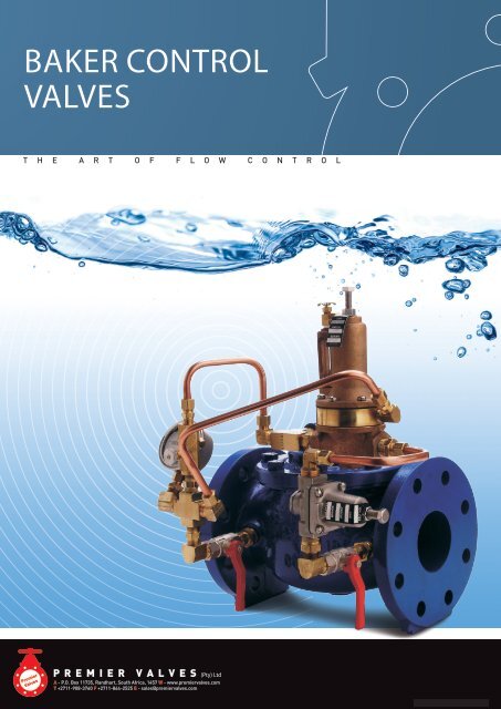
2<strong>BAKER</strong> <strong>CONTROL</strong> <strong>VALVES</strong>Control <strong>Valves</strong>THE <strong>BAKER</strong> VALVE “INSIDE STORY”As a control valve that has been in the South African market since1975 and that has always been well respected as one of the topplayers, <strong>BAKER</strong> is on a new mission to recapture the all importantcontrol valve market in South Africa. Now manufactured andmarketed by <strong>Premier</strong> <strong>Valves</strong>, <strong>BAKER</strong> is ready to set new standards inautomatic self actuated control valve technology. Following are someof the existing features and benefits of the <strong>BAKER</strong> control valve:• Larger flow passages with resultant greater capacities.• Greater cavitation resistance - 4:1 allowable pressure drop.• “Quad” Seal which provides a bubble tight closure and long lifewith reduced maintenance.As the only completely South African owned and manufacturedcontrol valve design the <strong>BAKER</strong> is currently available in pressurerating up to 50 bar and size range from 50mm to 600mm. A largetest rig at <strong>Premier</strong>’s premises enable development work to make<strong>BAKER</strong> “state of the art” with features customised for South Africanconditions. Designs are on the drawing board for 150 bar valves forthe SA Goldmines.ServiceBoth pre-sales and after sales services are crucial to the successof control valves. It is <strong>Premier</strong>’s mission to provide the best in boththese areas.Pre-sales serviceBecause so many factors need to be considered in correct selectionof control valves, staff and agent training has high priority toensure that the customer gets the right advice and ensure long andtrouble-free operation. To this end regular training programs areheld at <strong>Premier</strong>’s premises with an emphasis on both theoreticaland practical training on the test rig. <strong>Premier</strong> have for many yearssupplied complete Pressure Reducing stations up to 150 bar workingpressure where correct operation and safety features are importantto ensure safe and continuous water supply.Training programs arealso available for customers. After Sales service.<strong>Premier</strong> have aservice team which are available 24 hours a day to attend to fieldservice requirements.STANDARD CONSTRUCTION• Ductile Iron body and bonnet to BS 2789 Grade 420/12.• Buna-N Elastomers.• 316 Stainless Steel Body seat.• Bronze Pilots to ASTM B584 (C8440)• Brass fittings/plastic tubing.• 25 bars working pressure.• 85ºC for Buna-N. Other material available for temperatures up to150ºC.• Fusion Bonded Epoxy (FBE) coating to 250 microns.OPTIONAL ITEMS• Double “Power” chamber for low pressure reservoir or pumpcontrol applications.• Stainless Steel Pilots and fittings.• Position indicators.• Single and dual limit switches.• Low flow control pilot.• Flow limiting device.• High lift assembly for low pressure applications.• Special control circuit filters for dirty water.• Patented self cleaning orifices with variable speed forcontrolled closing.MANUFACTURING QUALITYThe “new” Baker is now manufactured to the highest quality toISO 9000 specifications.• NC machinery and redesigned tooling provide consistent qualityand repeatability.• A metrology department to verify correct dimensions.• Pressure testing of every valve.• Performance testing on a flow rig.A P.O. Box 11735, Randhart, South Africa, 1457 W www.premiervalves.comT +2711-908-3760 F +2711-864-2525 E sales@premiervalves.com
<strong>BAKER</strong> <strong>CONTROL</strong> <strong>VALVES</strong>3FeaturesFusion Bonded Epoxy Prolongs LifeThis coating is applied under rigorous preparation andapplication standards. It is non-porous, improving the flowco-efficiency of the valve and effectively sealing the castingfrom interaction with the controlled liquid. The coatingalso protects the valve from environmental attack. Thefinish prevents mineral build-up and rust (a major factor incontrol valve failure), simplifies maintenance, and prolongsthe life of the valve.Standard coating thickness: 250 microns.Other coatings available on request.Superior PerformanceThe design and innovative features incorporated intoevery Baker Automatic Control valve meansconsistent, dependable, high performance, positivecontrol and long life.Efficient DesignThe main valve is diaphragm actuated, hydraulicallyoperated. It consists of only four major components.The body and cover plus interior seat anddiaphragm/stem assembly, which is the only movingpart in the main valve.Variable Volume Cover ChamberA synthetic rubber/nylon diaphragm, of reinforcedBuna N materials, is assembled between the valvebody and cover. This creates a sealed chamber intowhich line fluid and pressure is introduced. Varyingthe amount of pressure accurately positions the stemassembly to open, close or modulate the valve asrequired.Precise Alignment And Stable ThrottlingA cover bearing and integral seat bearing guides thestem assembly for precise alignment with the seat.Coupled with the quad seal retainer plate, thisalignment assures progressive opening/closing flows,stable throttling, low friction operation and positiveclosure.Drip Tight SealBaker leads the automatic valve industry by beingthe first to incorporate the dynamic quad seal.The seat is retained on three ½ sides and iscompletely out of the flow path. It provides positiveclosure while eliminating the need to “bite” into theseal, adding years to the valve’s live. Each quad sealhas two usable sides. The Quad Seal has been in usefor many years and has reduced maintenance by aconsiderable amount.A P.O. Box 11735, Randhart, South Africa, 1457 W www.premiervalves.comT +2711-908-3760 F +2711-864-2525 E sales@premiervalves.com
4<strong>BAKER</strong> <strong>CONTROL</strong> <strong>VALVES</strong>OperationSystem of OperationThe Baker hydraulic control valve system is based on a robust,reliable, hydraulically operated, diaphragm actuated valve with,which various controls may be incorporated, either singly orin combination with each other, to provide any conceivableoperation that may be required for regulating the flow of water.PilotsUp to 1500 combinations of pilot arrangements areavailable and these are affected by the use of the followingbasic functions:Function 10Function 12Function 13Function 14Function 15Function 15-1Function 16Function 22Function 22-1Function 27Float level controlDifferential relief controlSolenoid controlRate-of-flow controlPressure reducing control(integrally sensed)Pressure reducing control(Remotely sensed)Pressure sustaining/reliefcontrolAccelerator control(With an integral orifice)Accelerator controlAltitude level controlValve ClosedThe valve closes when pressure is directed into the valvecover chamber above the diaphragm. An independentoperating supply may be used if its pressure is equal to, orgreater than the pressure at the valve inlet.These functions may be supplemented by the use of thefollowing accessories:Function 50Function 51Function 60Function 60-1Valve position indicatorsLimit switchesFlow clean strainers‘Y’ pattern strainersValve OpenThe valve opens fully when there is no pressure in the coverchamber and at least 50 kPa line pressure at the valve inlet.Valve ModulatingModulating action can be obtained by installing a controlsystem to the basic valve. Various controls are available tomodulate and compensate for pressure, flow rate, or liquidlevel changes.A P.O. Box 11735, Randhart, South Africa, 1457 W www.premiervalves.comT +2711-908-3760 F +2711-864-2525 E sales@premiervalves.com
<strong>BAKER</strong> <strong>CONTROL</strong> <strong>VALVES</strong>5DimensionsStandard Rating SG Iron Construction: 25BarHigh Pressure Rating Steel Construction: 50BarTemperature BunaN 85ºCViton 150ºCMaterial of Construction1 Cover S.G. 420/122 Bearing Phosphor Bronze3 Spring Stainless SteelAvailable In Standard Flange DrillingBS 4504 T10, T16, T25BS 10 TD, TE, TFANSI 150, 300Hydraulic Control PilotsBodies:Brass-ASTM B584Alloy:C84400Internals: Stainless Steel - AISI 303Elastomers: Buna N (Nitrile)(Other materials available ie. Stainless Bodies)AccessoriesSuch as a position indicator, high lift assembly,flow limiting devices etc. are normally brass butavailable in Stainless steel.4 Stem nut Stainless Steel /Galvanised Nyloc5 Diaphragm washer S.G.420/12 or Bronze6 Stud Grade 8.8 Galv7 Stud nut Grade 8.8 Galv8 ** Diaphragm Buna N9 Body S.G.420/1210 Quad ring retainer S.G.420/12 or Bronze11 ** Quad ring seal Nitrile Rubber12 Seat Stainless Steel13 Seat gasket Silicone14 Quad ring washer Stainless steel15 Stem Stainless Steel16 Spacer (150-400mm) S.G.420/1217 ** ‘O’ ring Nitrile Rubber**Recommended SparesStandard Items With Hook Up• 3 x Isolating cocks• Brass fittings and nylon tubing• ‘Y’ Strainer• 2 x Pressure gauges for Pressure Control <strong>Valves</strong>A P.O. Box 11735, Randhart, South Africa, 1457 W www.premiervalves.comT +2711-908-3760 F +2711-864-2525 E sales@premiervalves.com
6<strong>BAKER</strong> <strong>CONTROL</strong> <strong>VALVES</strong>Power ChamberPOWER CHAMBER HYDRAULIC <strong>CONTROL</strong> VALVE (AVAILABLE AS OPTIONAL FEATURE)Power Chamber Feature On/OffAlthough this can be used for modulating control, the mostcommon use for the power chamber is to permit the valve toopen when the supply pressure is low. The valve bias spring isomitted in this arrangement and it is essential that the valve issupplied with slow closing speed control to prevent waterhammer. The most usual applications for the Power Chamberare in Level control when residual pressure is very low and inPump Control to ensure the valve goes fully open and minimiseenergy consumption.Supply pressure is fed both under the valve seat and under thediaphragm via a 3-way pilot to the lower diaphragm chamber.This provides relatively large valve opening forces even at lowpressure. To close, the supply pressure is switched to the upperdiaphragm chamber.A secondary advantage of the Power Chamber is that thediaphragm is protected from damage caused by particles in theflow stream.The CV value of the Power Chamber Valve is slightly larger than thestandard valve because the seat no longer has an integral bearing.A P.O. Box 11735, Randhart, South Africa, 1457 W www.premiervalves.comT +2711-908-3760 F +2711-864-2525 E sales@premiervalves.com
<strong>BAKER</strong> <strong>CONTROL</strong> <strong>VALVES</strong>7Level Control OverviewThe Baker valve can be used to control Water Level inReservoirs and Tanks in a variety of different ways dependingon many factors such as Pressure and Flow conditions andconfigurations of the installation. A logical way to classify thedifferent methods to control level is by On-off or Modulation.Within both groups an almost unlimited combination of otherfunctions can be added such as Pressure Sustaining, rate ofFlow control, Solenoid override etc, which makes the BakerControl valve very versatile. In both groups the choice can bemade to install the valve as a top-of-reservoir valve mountedinside (or outside) the reservoir, or as a bottom entry with thevalve mounted on the bottom of the reservoir. Please note thata stilling well should be installed with the float pilot if waterturbulence could affect the operation. The stilling well can be anappropriate diameter plastic pipe (normally 200mm).Hydraulic ConditionsIn order for Level control valves to operate effectively andprovide long trouble-free life, flow and pressure conditionshave to be investigated. Two pressure conditions can createproblems i.e.1) High PressureDam (or reservoir) control valves have always been susceptible totwo potential problems caused by high pressure conditions whichcan be overcome if one is aware of what the problems are.CavitationMost control valves can handle a pressure drop ratio of no morethan 3:1. Because of it’s unique features the Baker control valvecan handle a 4:1 pressure drop ratio. Even so in a Level controlapplication if one assumes a back pressure of 1 bar from thehead of the reservoir downstream of the valve, the valve can onlyeffectively cope with 4barupstream in order to provide a long life.High Flow RatesIf a level control valve is allowed to go fully open and dynamichead is above 1.5bar, a flow rate far beyond the recommendedcan occur which can cause further damage. In both of the abovesituations the extent of the valve’s life will be determined by thelevel of the upstream pressure. If the discharge into the dam isfree with the valve installed at the end of the line, the problem isnot as severe because cavitation will occur outside the valve, butone still has the high velocity problem.Our recommendations for these installations are outlined below.· Upstream Dynamic head between 5 and 10 barInstall a Flow control pilot on the Baker Level Control Valve tolimit flow rate to an acceptable level and install an orifice platedownstream of the valve to provide an artificial back pressure.The valve will still experience cavitation during the opening andclosing cycles, but as long as the cycles are not too frequentand closing and opening speed is not too long, the aboverecommendations should ensure a reasonable valve life.· Upstream Dynamic head over 10 barInstall a Flow control pilot on the Baker Level Valve and install anadditional Pressure Reducing valve upstream of the Level controlvalve. The Pressure Reducing valve can be either a pilot operatedBaker valve or a <strong>Premier</strong> Ratio Reducing valve which operateswithout a pilot and can handle pressure drops of up to 5:1.2) Low PressureFlowing line pressure should be 50kPa or more to ensure thatsufficient head is available to open the valve fully. This assumesthere is not pressure in the control chamber. The other factor tobe aware of is that with the valve at the bottom of the reservoirand the float pilot at the top, the static head in the control tubingis the minimum pressure which can be achieved in the controlchamber with the normal pilot hook-up. A “rule of thumb”which can be used to check this condition is as follows:The flowing line pressure in PSI should be greater than or equalto the vertical distance in feet between the valve and the floatpilot.A P.O. Box 11735, Randhart, South Africa, 1457 W www.premiervalves.comT +2711-908-3760 F +2711-864-2525 E sales@premiervalves.com
8<strong>BAKER</strong> <strong>CONTROL</strong> <strong>VALVES</strong>Control <strong>Valves</strong>FIG B110-10Float Control - Modulating (Constant Level)The FIG B110-10 maintains a constant level in storage tanks andreservoirs. Valve controlled flow into the tank is proportional todischarge flow, keeping the tank full.NOTE:The modulating float control FIG B110-10, is remote mountedunless specified valve mounted. A stilling well around the floatshould be installed if the liquid surface is subject to turbulence,ripples or wind.Quick Sizing: Valve size same as fill line or one size smaller ifdischarge line is smaller than the fill. Match size/capacity todischarge requirements.VALVE FUNCTION• Maintains a constant liquid level in atank.• Remote mounted pilot is sensitive toslight changes in level and controlsmain valve:- Opens when level drops- Closes when level risesCOMPONENTS1. Main Valve2. Fig. 10-11 Modulating Float Control3. Needle Valve - Adj. Closing SpeedACCESSORIESLocated as indicatedIncluded as marked• X• Y• P• FC• L- Isolation Cocks-Y Strainer- Position Indicator- Flo-Clean Strainer- Limit SwitchFIG B110-14Float Control-On/Off (Open/Close) Adj. Hi/Lo LevelsThe FIG B110-14 opens fully when the level reaches the presetlow point and shuts off drip tight when the high level is reached.The on/off ball valve pilot is equipped with a vertical rod whichallows the float to rise and drop to the adjustable upper andlower stops.NOTE:The pilot is remote mounted unless it is specified valvemounted. Standard equipped with brass rods and plasticfloats. Stainless steel rods and floats are available. Provide astilling well around the float if a liquid surfaceIs subject to turbulence, ripples or wind.Specify: Valve mounted pilot is required and valve dischargehorizontal or vertical.Quick Sizing: Valve size same as fill line or one size smaller.VALVE FUNCTION• Valve opens when float reaches lowerlevel stop (adjustable)• Valve closes when float reachesupper level stop (adjustable)• High and low level adjustmentsallows for calculated draw down- Opens when level drops- Closes when level risesCOMPONENTS1. Main Valve2. Fig. 10-13 Float Pilot3. Level Adjustment Stops3A - Upper Level3B - Lower Level• X• Y• FC• L- Isolation Cocks-Y Strainer- Flo-Clean Strainer- Limit SwitchACCESSORIESLocated as indicatedIncluded as markedLarge size valves may requireand accelerates a Pilot.A P.O. Box 11735, Randhart, South Africa, 1457 W www.premiervalves.comT +2711-908-3760 F +2711-864-2525 E sales@premiervalves.com
<strong>BAKER</strong> <strong>CONTROL</strong> <strong>VALVES</strong>9AltitudeFIG B127-1Altitude Valve - Pressure ReducingProvides automatic filling of elevated tanks or reservoirs.When the altitude control senses a drop in level below thepredetermined set-point, the valve opens to fill the tank. Supplypressure must be greater than static head pressure. Discharge ofthe tank is by a separate line.NOTE:Adjustable ranges:1.5m - 6m3m - 22m15m - 60mQUICK SIZING: Valve size, line size or one size smaller.FIG B127-1Altitude Valve - Two Way Flows (Tank Fill & Discharge)Provides automatic filling of elevated tanks or reservoirs. Supplypressure must be greater than static head pressure. When thealtitude control senses a drop in level below the predeterminedset-point, the valve opens to fill the tank. The valve opens for tankdischarge when tank head pressure is greater than valve inletpressure.NOTE:Adjustment ranges: 1.5m - 0.6m3m - 22m15m - 60mQuick Sizing: Valve size, line size or one size smaller.VALVE FUNCTION• Closes when reservoir level reachespilot setting• Opens a pproximately 300mm lower.COMPONENTS1. Main Valve2. Fig. 22-1 Accelerator Control forsizes larger than 150mm.3. Fig. 27 Altitude Control4. Check Valve5. Needle Valve - Adj. Opening Speed6. Needle Valve - Adj. Closing Speed7. 3-Way Ball Valve8. 263AP PilotP - Position IndicatorFC - Flo-Clean Strainer• X• Y• L -- Isolation Cocks- Y Strainer(EliminatesFlo-Clean)Limit SwitchACCESSORIESLocated as indicatedIncluded as markedPoints to consider:Tank discharge flow requires a valve inlet(system pressure) to be 13 kPa less than tank head pressure.VALVE FUNCTION• Tank fill• Opens when reservoir level dropsbelow pilot setting (adjustable)• Closes when reservoir level reachespilot setting• Tank Discharge• Opens when valve inlet / systempressure is below tank headACCESSORIESLocated as indicatedIncluded as marked• X• Y• FC• L- Isolation Cocks- Y Strainer- Flo-Clean Stainer- Limit SwitchCOMPONENTS1. Main Valve2. Fig. 22-1 Accelerator Control forsizes larger than 150mm.3. Fig. 27 Altitude Control4. Check Valve5. Needle Valve - Adj. Opening Speed6. Needle Valve - Adj. Closing Speed7. 3-Way Ball ValveP - Position IndicatorA P.O. Box 11735, Randhart, South Africa, 1457 W www.premiervalves.comT +2711-908-3760 F +2711-864-2525 E sales@premiervalves.com
10<strong>BAKER</strong> <strong>CONTROL</strong> <strong>VALVES</strong>AltitudeFIG B127-11Altitude Valve - One Way Flow (Tank Fill)Delayed Opening For Adjustable Tank Draw-DownProvides automatic filling of elevated tanks or reservoirs. Supplypressure must be greater than static head pressure. Dischargeof the tank is by a separate line. On lowering of tank level thealtitude control is prevented from sensing the drop until apredetermined point at which time the altitude control opens thevalve filling the tank to the specific level.NOTE:Adjustable range:1.5m - 6m3m - 22m15m - 60mAdjustment rangedelayed level drop: 0.6m - 4.5mVALVE FUNCTION• Opens when reservoir level drops below point setting(Adjustable to allow for calculated drop in tank level before opening)• Closes when reservoir level reaches pilot settingCOMPONENTS1. Main Valve 6. Needle Valve - Adj. Opening Speed2. Fig. 12 - Delayed Opening Control 7. Needle Valve - Adj. Closing Speed3. Fig. 22-1 - Accelerator Control 8. 3-Way Ball Valve4. Fig. 27 Altitude Control P - Fig. 50 Position Indicator5. Check Valve FC - Flo-Clean StrainerACCESSORIESLocated as indicatedIncluded as marked• X• Y• L- Isolation Cocks- Y Strainer- Limit SwitchQuick Sizing: Valve size, line size or one size smaller.• Refer to Engineering Data - Flow Capacity Chart• Pressure drops at required flowRefer to Engineering Data - Pressure Drop Chart• Inlet pressure vs. Tank height to fillA P.O. Box 11735, Randhart, South Africa, 1457 W www.premiervalves.comT +2711-908-3760 F +2711-864-2525 E sales@premiervalves.com
<strong>BAKER</strong> <strong>CONTROL</strong> <strong>VALVES</strong>11Solenoid Control <strong>Valves</strong>FIG B113-12Solenoid On/Off (Open/Close)Operated by a 3-way solenoid, the main valve opens fully orclosed drip-tight depending upon the actuation position of thesolenoid, energized to open/energized to close. The valve maybe remote operate by timers, relays, probes or any triggereddevice to the solenoid. The valve can be operated with 2 x 2-waysolenoids for modulating control from a PLC.NOTE:Energized to open valve.Optional: energized to close valve.At time of order, advise our factory manager or yoursystem working pressure for correct solenoid selection.110-220 VAC, 50-60 Hz standardOptional: specify voltage required.Enclosure General Purpose (NEMA 1,2,3,3S,4,4X)Optional: explosion proof (NEMA 3,3S,4,4X,6,6P,9)Manual operator standardOptional: Opening and/or closing speed.Quick Sizing: Valve size same as line or one size smaller.Points to consider:• Refer to Engineering Data - Flow Capacity Chart• Pressures drop at required flow• Refer to Engineering Data - Pressure Drop ChartVALVE FUNCTION• Electrically operated on/off (open/close) control valvesCOMPONENTS1. Main Valve2. 3-Way Solenoid3. Flo-Clean StrainerACCESSORIESLocated as indicatedIncluded as marked• X - Isolation Cocks• Y -Y Strainer (EliminatesFlo-Clean)• ACS - Adj. Closing Speed• AOS - Adj. Opening SpeedFIG B113-6Solenoid On/Off (Open/Close)This configuration has an accelerator pilot to speed up valvereaction time if required. A 3-way solenoid and auxiliary 3-portaccelerator cause the main valve to open fully or close drip-tightdepending upon the actuation position of the solenoid, energizedto open/energized to close. The high capacity accelerator assuresquick valve response to the solenoid signal regardless of the mainvalve size. The valve may be remote operated by timers, relays,probes or any triggering device to the solenoid.NOTE:Energized to open valve.Optional: energized to close valve.At time of order, advise factory actual system workingpressure for correct solenoid selection.110-220 VAC, 50-60 Hz standardOptional: specify voltage required.Enclosure General Purpose (NEMA 1,2,3,3S,4,4X)Optional: explosion proof (NEMA 3,3S,4,4X,6,6P,7,9)Manual operator standardStandard with adjustable opening and closing speed.Quick Sizing: Valve size same as line or one size smaller.Points to consider:• Refer to Engineering Data-Flow Capacity Chart• Pressures drop at required flow• Refer to Engineering Data-Pressure Drop ChartVALVE FUNCTION• Electrically operated on/off (open/close) control valves• High capacity control for fastresponse• Water application-to atmosphere.• Fuel application-piped to valveoutlets.• Drains cover of accelerators.ACCESSORIESLocated as indicatedIncluded as markedCOMPONENTS1. Main Valve2. 3-Way Solenoid3. Flo-Clean Strainer4. Needle Valve - Adj. Closing Speed5. Needle Valve - Adj. Opening Speed6. Accelerator Control• X - Isolation Cocks• Y -Y Strainer (EliminatesFlo-Clean)• ACS - Adj. Closing Speed• ADS - Adj. Opening SpeedA P.O. Box 11735, Randhart, South Africa, 1457 W www.premiervalves.comT +2711-908-3760 F +2711-864-2525 E sales@premiervalves.com
12<strong>BAKER</strong> <strong>CONTROL</strong> <strong>VALVES</strong>Pump ControlFIG B113-46Booster Pump Control (<strong>Valves</strong> 150mm and smaller)A solenoid operated pump control for controlled opening andclosing on a pump start-up and shut down. Equipped withhydraulic check features to close valve on pressure reversal andshut-off pumps in an event of pump failure. Valve and pumpoperations are interlocked by a limit switch assembly.NOTE:Energized to open valve.At time of order, advise factory actual system workingpressure for correct solenoid selection.110-120 VAC, 50-60 Hz standardOptional: specify voltage required.Solenoid enclosure NEMA 1,2,3,3S,4,4XOptional: explosion proof NEMA 3,3S,4,4X,6,6P,7,9Manual operator standardLimit switch enclosure general purposesOptional: explosion proof.Standard with adjustable opening and closing speed.Quick Sizing: Valve size same as line.Points to consider:• Refer to Engineering Data - Flow Capacity Chart• Pressures drop at required flow• Refer to Engineering Data - Pressure Drop ChartVALVE FUNCTION• Opens at a controlled rate on thepump start-up (adjustable)• Closes at a controlled rate on pumpshut-off (adjustable)• Valve and pumps are electricallyinterlocked so that power is shut-offwhen the valve is in near closedpositionACCESSORIESLocated as indicatedIncluded as markedCOMPONENTS1. Main Valve2. 3-Way Solenoid3. Fig. 51 Limit Switch FC - Flow CleanStrainer4. Speed5. Needle Valve - Adj. Closing Speed6. Check Valve• X• Y- Isolation Cocks- Y StrainerFIG B113-21Booster Pump Control (<strong>Valves</strong> 200Mm And Larger)A solenoid operated pump control for controlled opening andclosing on a pump start-up and shut down. Equipped withhydraulic check features to close valve on pressure reversal. Valveand pump operation are interlocked by a limit switch assembly.NOTE:Energized to open valve.At time of order, advise factory actual system workingpressure for correct solenoid selection.110-120 VAC, 50-60 Hz standardOptional: specify voltage required.Solenoid enclosure NEMA 1,2,3,3S,4,4XOptional: explosion proof NEMA 3,3,S,4,4X,6,6P,7,9Manual operator standardLimit switch enclosure general purposesOptional: explosion proof.Standard with adjustable opening and closing speed.Quick Sizing: Valve size same as line.Points to consider:• Refer to Engineering Data - Flow Capacity Chart• Pressures drop at required flow• Refer to Engineering Data - Pressure Drop ChartVALVE FUNCTION• Opens at a controlled rate on pumpstart-up (adjustable)• Closes at a controlled rate on pumpshut-off (adjustable)• Valve and pump are electricallyinterlocked so that power is shut-offwhen the valve is in near closedposition• Check feature closes valve whendischarge pressure exceeds inletPressure(Power failure or pump failure)ACCESSORIESLocated as indicatedIncluded as markedCOMPONENTS1. Main Valve - Adj. Closing Speed2. 3-Way Solenoid3. Fig. 51 Limit Switch FC - Flow CleanStrainer4. Needle Valve - Adj. Opening Speed5. Needle Valve6. Check Valve• X• FC• Y- Isolation Cocks- Flo-Cleaner Strainer- Y StrainerA P.O. Box 11735, Randhart, South Africa, 1457 W www.premiervalves.comT +2711-908-3760 F +2711-864-2525 E sales@premiervalves.com
<strong>BAKER</strong> <strong>CONTROL</strong> <strong>VALVES</strong>13Pump ControlFIG B413-21Booster Pump Control / Mechanical Lift CheckA solenoid operated pump control for controlled opening andclosing on a pump start-up and shut down. Equipped withhydraulic check features to close valve on pressure reversaland shut-off pump in an event of pump failure. Valve and pumpoperations are Interlocked by a limit switch assembly.NOTE:Energized to open valve.At time of order, advise factory actual system workingpressure for correct solenoid selection.110-220 VAC, 50-60 Hz standardOptional: specify voltage required.Solenoid enclosure NEMA 1,2,3,3S,4,4XOptional: explosion proof NEMA 3,3S,4,4X,6,6P,7,9Manual operator standardLimit switch enclosure general purposesOptional: explosion proof.Standard with adjustable opening and closing speed.QUICK SIZING: Valve size same as line.Points to consider:• Refer to Engineering Data - Flow Capacity Chart• Pressures drop at required flow• Refer to Engineering Data - Pressure Drop ChartVALVE FUNCTION• Opens at a controlled rate on thepump start-up (adjustable)• Closes at a controlled rate on pumpshut-off (adjustable)• Valve and pumps are electricallyinterlocked so that power is shut-offwhen the valve is in near closedposition• Mechanical lift-check providesquick closure of the valve to preventreverse flowACCESSORIESLocated as indicatedIncluded as markedCOMPONENTS1. Main Valve 5. Needle Valve - Adj.Opening Speed2. 3-Way Solenoid 6. Check Valve3. Fig. 22-1 Accelerator Control 7. Fig.51 Limit Switch4. Needle Valve - Adj. Closing Speed• X• Y• FC- Isolation Cocks- Y Strainer- Flo-Cleaner StrainerFIG B513-5Booster Pump Control / Dual Chamber / Lift CheckA solenoid operated pump control for controlled opening andclosing on a pump start-up and shut down. Built on the dualchamber Baker 518 main valve. Equipped with mechanical liftcheckfeatures to close valve the moment flow stops, preventingpressure reversal. Valve and pump operations are interlocked by alimit switch assembly.NOTE:Energized to open valve.110-220 VAC, 50-60 Hz standardOptional: specify voltage required.Solenoid enclosure NEMA 1,2,3,3S,4,4XOptional: explosion proof NEMA 3,3,S,4,4X,6,6P,7,9Manual operator standardLimit switch enclosure general purposesOptional: explosion proof.Standard with adjustable opening and closing speed.QUICK SIZING: Valve size same as line.Points to consider:• Refer to Engineering Data - Flow Capacity Chart• Pressures drop at required flow• Refer to Engineering Data - Pressure Drop ChartVALVE FUNCTION• Opens at a controlled rate on the pumpstart-up (adjustable)• A Upper Chamber connected to solenoidexhaust port• B Lower Chamber connected to valve inletport (supply port)• Closes at a controlled rate on pump shutoff(adjustable)• A Upper Chamber connected to valve inletport (pressure port)• B Lower Chamber connected to solenoidexhaust port• Valve and pumps are electricallyinterlocked so that power is shut-offwhen the valve is in near closed position(adjustable with a limit switch)• Mechanical lift-check provides quickclosure of the valve to prevent reverse flowCOMPONENTS1. Main Valve W/Mechanical Lift-Check2. 4-Way Solenoid3. Check Valve4. Fig. 51 Limit Switch5. Flow-Control - Adj. Opening Speed6. Flow-Control - Adj. Closing SpeedACCESSORIESLocated as indicatedIncluded as marked• FC• Y• X• L- Flo-Cleaner Strainer- Y Strainer- Isolation Cocks- Second Limit SwitchA P.O. Box 11735, Randhart, South Africa, 1457 W www.premiervalves.comT +2711-908-3760 F +2711-864-2525 E sales@premiervalves.com
14<strong>BAKER</strong> <strong>CONTROL</strong> <strong>VALVES</strong>Pump ControlFIG B513-6Deep Well Pump ControlThe FIG B513-6 pump control valve starts in an open positionduring the pump start-up, purging the deep well of air anddebris to atmosphere. Controlled closing of the valve, opens themainline check valve, gradually increasing line pressure. Thevalve reopens during shut down cycles to gradually decreaseline pressure and prevent shock. Valve and pump operations areinterlocked by a limit switch assembly.NOTE:Energized to close valve.110-220 VAC, 50-60 Hz standard.Optional: specify voltage required.Solenoid enclosure NEMA 1,2,3,3S,4,4XOptional: explosion proof NEMA 3,3S,4,4X,6,6P,7,9Manual operator standardLimit switch enclosure general purposesOptional: explosion proofStandard with adjustable opening and closing speed.Quick Sizing: Valve size one to two sizes smaller than main linePoints to consider:• Refer to Engineering Data - Flow Capacity Chart• The deep well pump valve must be sized so it relieves toatmosphere pump discharge pressure in excess of thenormal system static pressure. This is necessary to preventpremature opening of the main line check valve.• Refer to Engineering Data - Pressure Drop Chart. If flowvelocity exceeds 15 metres per second use next valve size.• Pressure drop at required flow.• Refer to Engineering Data - Pressure Drop ChartVALVE FUNCTION• Discharge deep well air and debris bybeing in an open position on thepump start-up.• Closes at a controlled rate (adjustable)• Eliminating surges when pumping intomain line (works in conjunctionwith controlled opening check valves inmain line)• Opens at a controlled rate (adjustable)eliminating surges upon pump shut-off• Valve and pumps are electricallyinterlocked so pump power is shutoffwhen valve is in a near full openposition (adjustable)COMPONENTS1. Main Valve2. Figure 51 Limit Switch3. 4-Way Solenoid4. Flow Control - Adj. Opening Speed5. Flow Control - Adj. Closing Speed6. Y-StrainerACCESSORIESLocated as indicatedIncluded as marked• X- Isolation CocksFIG B114Rate Of Flow“R” Indicates flow over the seat (failed closed) Maintains aconstant flow rate, adjustable, regardless of fluctuations in linepressure. The rate of flow pilot senses the differential pressuresacross a thin edged orifice plate mounted in the valve inlet flange.It responds to changes in pressure and modulates the main valveto maintain the desired flow.SPECIFY:Desired flow rates at time of order.FIG 114R: Flow over the seat (fail closed)FIG 114: Flow under the seat (fail open)Additional combination functions:114-1R Rate of Flow / Solenoid On-Off114-2R Rate of Flow / Pressure Reducing114-8R Rate of Flow / Pressure SustainingQuick Sizing: Stay within parameters of a capacity chart (below)Points to consider:• Orifice plate sized per application and per your acceptablepressureVALVE FUNCTIONLimits flow rate to a constant presetmaximum (adjustable)COMPONENTS1. Main Valve2. Figure 51 Limit Switch3. Needle Valve - Adj. Closing Speed4. Orifice PlateACCESSORIESLocated as indicatedIncluded as marked• AOS - Adj. Opening Speed• X - Isolation Cocks• Y - Y Strainer• FC - Flo-Clean Strainer• P - Position Indicator• L - Limit SwitchValve Size- mm5080100150200250300350400600MinimumFlow RateLitre /Second12361219253153190MaximumFlow RateLitre /Second1430501152003104405507001700A P.O. Box 11735, Randhart, South Africa, 1457 W www.premiervalves.comT +2711-908-3760 F +2711-864-2525 E sales@premiervalves.com
<strong>BAKER</strong> <strong>CONTROL</strong> <strong>VALVES</strong>15Direct Acting Pressure Reducing Valve Series B115FunctionThe control is a diaphragm actuated pressure reducingvalve, which is normally in an open position due to theforce of the spring setting above the diaphragm. Thevalve moves automatically toward the seat (modulates)when the downstream pressure exceeds the adjustablespring setting, thus controlling the pressure to thedesired set point.Start-Up/AdjustmentPressure adjustment is made by turning the adjustingscrew clockwise to increase the pressure and counterclockwiseto decrease the setting.SpecificationsSize: 1/2"Temperature range: 120 FMaterials:Cover - Epoxy Coated AluminumBody - BrassRubber Parts and Diaphragm - Buna-NStem - Stainless steelSpring Range - 0-30, 20-1 75FIG B115Pressure ReducingAutomatically reduces a higher pressure to a constantlower outlet pressure regardless of changing flow rateand / or varying inlet pressure. Refer to FIG B115-7 fordead-end systems and / or systems using high demand,on-off equipment.NOTE:Adjustment range:Standard: 20-1190 kPaOptional: 0-638 kPa100-2040 kPa(Stainless steel control)QUICK SIZING:Valve size one size smaller than line.Points to consider:• See Engineering Data - Pressure Reducing Sizing• Check maximum and minimum flow• Check pressure drop - pressure reducing valves orcavitation chartsVALVE FUNCTION• Reduce higher inlet pressure toconstant lower outlet pressure(adjustable)COMPONENTS1. Main Valve2. 263 Reducing Valve3. Fixed Orifice4. Flow Control - Adj. Opening SpeedACCESSORIESLocated as indicatedIncluded as marked• X - Isolation Cocks• Y - Y Strainer• P - Position Indicator• FC - Flo-Clean Strainer• L - Limit Switch• AOS - AdjustableClosing SpeedA P.O. Box 11735, Randhart, South Africa, 1457 W www.premiervalves.comT +2711-908-3760 F +2711-864-2525 E sales@premiervalves.com
16<strong>BAKER</strong> <strong>CONTROL</strong> <strong>VALVES</strong>Pressure Reducing <strong>Valves</strong>FIG B115-2Pressure Reducing / SustainingAutomatically reduces a higher inlet pressure to a constant loweroutlet pressure regardless of changing flow rate and/or varyinginlet pressure. Equipped with a pressure sustaining control whichprevents the upstream pressure from dropping below a presetminimum.NOTE:Downstream Pressure Adjustment range:Standard: 20-1190 kPaOptional: 0-204 kPa100-2040 kPa(Stainless steel control)Upstream Pressure Adjustment range:Standard: 20-1360 kPaOptional: 0-204 kPa100-2040 kPaAdditional Combinations:115-11 Reducing/Sustaining/Check115-32 Reducing/Sustaining/SolenoidQuick Sizing:Valve size one size smaller than line.Points to consider:• See Engineering Data - Pressure Reducing Sizing• Check maximum and minimum flow• Check pressure drop - pressure reducing valves orcavitation chart.VALVE FUNCTION• Reduce higher inlet pressure toconstant lower outlet pressure(adjustable)• Prevents upstream pressure fromdropping below a preset minimum(adjustable)COMPONENTS1. Main Valve2. 263 Pressure Reducing Control3. Pv20 Sustaining Control4. Flow Control - Adj. Opening Speed5. Fixed OrificeACCESSORIESLocated as indicatedIncluded as marked• X• Y• L• FC• P• ACS- Isolation Cocks- Y Strainer- Limit Switch- Flo-Clean Strainer- Position Indicator- Adjustable ClosingSpeedFIG B115-3PRESSURE REDUCING / CHECKAutomatically reduces a higher inlet pressure toa constant lower outlet pressure regardless of changingflow rate and/or varying inlet pressure.Equipped with a pressure sustaining control which prevents theupstream pressure from dropping below a preset minimum.Equipped with Check feature to prevent reverse flow if upstreampressure is lower than downstream pressure.NOTE:Adjustment range:Standard: 20-1190 kPaOptional: 0-204 kPa100-2040 kPa(Stainless steel control)Quick Sizing:Valve size one size smaller than line.Points to consider:• See Engineering Data - Pressure Reducing Sizing• Check maximum and minimum flow• Check pressure drop - pressure reducing valves orCavitation ChartVALVE FUNCTION• Reduces higher inlet pressure toconstant lower outlet pressure(adjustable)• Close when outlet-downstreampressure exceeds inlet/upstreampressure.COMPONENTS1. Main Valve2. Reducing Control3. Check Valve4. Flow Control - Adj. Opening Speed5. Fixed OrificeACCESSORIESLocated as indicatedIncluded as marked• X• Y• L• FC• P• ACS- Isolation Cocks- Y Strainer- Limit Switch- Flo-Clean Strainer- Position Indicator- Adjustable ClosingSpeedA P.O. Box 11735, Randhart, South Africa, 1457 W www.premiervalves.comT +2711-908-3760 F +2711-864-2525 E sales@premiervalves.com
<strong>BAKER</strong> <strong>CONTROL</strong> <strong>VALVES</strong>17Pressure Reducing / SustainingFIG B115-4Pressure Reducing / Solenoid On-OffAutomatically reduces a higher inlet pressure to a constant loweroutlet pressure regardless of changing flow rate and/or varyinginlet pressure.NOTE:Adjustment range:Standard: 20-1190 kPaOptional: 0-204 kPa100-2040 kPa(Uses stainless steel pilot)Solenoid max W.P.:At time of order, advise factory actual system workingpressure for correct solenoid selection.(Consult the factory if more than 1020 kPa)Enclosure NEMA 1,2,3,3S,4,4XOptional: Explosion proof NEMA 3,3S,4,4X,6,6P,7,9Additional Combinations:115-5 Pressure Reducing / Solenoid / CheckSpecify:Energized to open or energized to close main valve.Quick Sizing:Valve size one size smaller than line.Points to consider:• See Engineering Data - Pressure Reducing Sizing• Check maximum and minimum flow• Check pressure drop - cavitation chartVALVE FUNCTION• Reduce higher inlet pressure toconstant lower outlet pressure(adjustable)• Electrical on-off override of reducingfunctionCOMPONENTS1. Main Valve2. 263 Pressure Reducing Control3. 2-Way Solenoid4. Fixed Orifice5. Flow Control - Adj. Opening SpeedACCESSORIESLocated as indicatedIncluded as marked• X• Y• L• FC• P• ACS- Isolation Cocks- Y Strainer- Limit Switch- Flo-Clean Strainer- Position Indicator- Adjustable ClosingSpeedFIG B115-7Pressure Reducing / SurgeAutomatically reduces a higher inlet pressure to a constant loweroutlet pressure regardless of changing flow rate and/or varyinginletpressure. Should flow rate decrease rapidly a pressurecontrolled surge pilot closed the valve to prevent downstreampressure build-up. Excellent in dead-end systems and/or systemsusing high demand, on-off equipment.NOTE:Adjustment range:Standard: 20-1190 kPaOptional: 0-204 kPa100-2040 kPa(Uses stainless steel pilot)Additional Combinations:115-43 Reducing/Surge/Sustaining115-50 Reducing/Surge/CheckQuick Sizing:Valve size one size smaller than line.Points to consider:• See Engineering Data - Pressure Reducing Sizing• Check maximum and minimum flow• Check pressure drop - cavitation chartVALVE FUNCTION• Reduce higher inlet pressure toconstant lower outlet pressure(adjustable)• Closes quickly when outlet exceedsset point of surge control (adjustable)COMPONENTS1. Main Valve2. 263 Pressure Reducing Control3. PV20 Pressure Surge Control4. Fixed Orifice5. Flow Control - Adj. Opening SpeedACCESSORIESLocated as indicatedIncluded as marked• X• Y• L• FC• P• ACS- Isolation Cocks- Y Strainer- Limit Switch- Flo-Clean Strainer- Position Indicator- Adjustable ClosingSpeedA P.O. Box 11735, Randhart, South Africa, 1457 W www.premiervalves.comT +2711-908-3760 F +2711-864-2525 E sales@premiervalves.com
18<strong>BAKER</strong> <strong>CONTROL</strong> <strong>VALVES</strong>Pressure Reducing / Low FlowFIG B115-74Pressure Reducing / Low Flow By-Pass ValveAutomatically reduces a higher inlet pressure to a constantlower outlet pressure regardless of changing flow rate and/orvarying inlet pressure. Equipped with a low flow bypass featurewhich automatically by passes the main valve pressurefunction for low flow conditions.See sizing data on Page 25 for sizing parallel installations.COMPONENTS1. Main Valve2. Low Flow By-Pass Control- <strong>Valves</strong> 80mm & larger - 115Pressure Reducing Control- <strong>Valves</strong> 50mm & smaller - 263Pressure Reducing Control3. 263 Pressure Reducing Control4. Fixed Orifice5. Flow Control - Adj. Opening SpeedACCESSORIESLocated as indicatedIncluded as marked• X - Isolation Cocks• Y - Y-Strainer• FC - Flo-Clean Strainer• P - Position• L - Limit Switch• ACS - Adjustable Closing SpeedFIG PV 20CDirect Relief ControlFunction• Normally closed position, opens when pressure reachesset-point.Features• Responsive• Selectable spring ranges toallow for accurate, easy toadjust pressure setting.• Large diaphragm area• ½” ports.• Large seat area.• Ease of Maintenance• Can be serviced withoutremoval from line.• Replacement of elastomerparts is usually maximumrequired servicing.OperationThe PV20C is a normally closed, diaphragm actuated, springloaded, direct acting regulator. The pressure set point isadjustable within the spring range. Up stream pressureis sensed under the diaphragm. As upstream pressureincreases, the diaphragm pushes against the spring. The pilotstem/seat is pulled toward the open position, increasing flowthrough the pilot. As upstream pressure decreases underthe diaphragm, the spring pushes the stem/seat toward theclosed position restricting flow through the pilot. This sensitivespring/diaphragm interaction closely tacks and responds tochanges in upstream pressure.START-UP/ADJUSTMENTFollow the start-up procedure for theBaker function you have selected.1. Turn the screw Clockwise (IN)to increase the set-point you arecontrolling.2. Turn the screw Counterclockwise(OUT) to decrease the set-point youare controlling.INSTALLATIONIf the PV20CB is to be fieldinstalled, follow the steps below.1. Locate the flow arrow or bridgemarking and install the control sothe flow is under the seat.2. Typical application shown on theright.A P.O. Box 11735, Randhart, South Africa, 1457 W www.premiervalves.comT +2711-908-3760 F +2711-864-2525 E sales@premiervalves.com
<strong>BAKER</strong> <strong>CONTROL</strong> <strong>VALVES</strong>19Pressure Relief / SustainingFIG B116Pressure Relief / SustainingInstalled on a bypass line, mainline pressure is accuratelycontrolled by relief of excess pressure. Installed in a mainline itprevents upstream pressure from dropping below a presetminimum. For very fast reaction requirement refer to <strong>Premier</strong> forinfo on gas loaded surge relief valve.NOTE:Adjustment range:Standard: 20-1360 kPaOptional: 0-204 kPa100-2040 kPa116 RELIEFQuick Sizing: Valve size one or two sizessmaller than main line.Points to Consider:• Refer to Engineering Data - FlowCapacity ChartVALVE FUNCTIONMaintain constant upstream pressure(inlet to valve) by relieving excessPressure.COMPONENTS1. Main Valve2. PV20C Sustaining Control3. Needle Valve - Adj. Closing SpeedAdditional relief/sustaining functions:- 116FM/1116FM(U.L. Listed/F.M. Approved for fire pumprelief service)- 116-5 Pressure Sustaining / Check- 116-25 Differential Pressure Sustaining- 116-24 Differential PressureSustaining / Check116 SUSTAININGQuick Sizing: Valve size same as line.Points to Consider:• Refer to Engineering Data - FlowCapacity Chart• Pressure drops at required flow• Refer to Engineering Data - PressureDrop ChartACCESSORIESLocated as indicatedIncluded as marked• X - Isolation Cocks• Y - Y-Strainer• P - Position Indicator• FC - Flo-Clean Strainer• L - Limit Switch• AOS - Adj. Opening SpeedFIG B116-31Pressure Sustaining / Solenoid On-OffInstalled in a mainline, and it prevents upstream pressure fromdropping below a preset minimum. Solenoids’ override of thesustaining function allows for electrical on-off operation.NOTE:Adjustment range:Standard: 20-1360 kPaOptional: 0-204 kPa, 100-2040 kPaAt time of order, advise factory actual system workingPressure for correct solenoid selection.(Consult the factory if more than 1020 kPa)Enclosure: NEMA 1,2,3,3S,4,4XOptional: Explosion proofNEMA 3,3S,4,4X,6,6P,7,9Specify energized to open or energized to close main valve.Quick Sizing: Valve size same size as line.Points to consider:• Refer to Engineering Data - Flow Capacity Chart• Pressure drops at required flowRefer to Engineering Data - Pressure Drop ChartVALVE FUNCTION• Maintain constant upstream pressure(inlet to valve) by relieving excessPressure.• Solenoid provides electrical on/offoverride of relief/sustaining functionCOMPONENTS1. Main Valve2. PV20C Sustaining Control3. Needle Valve - Adj.Restriction - Closing4. 2-Way SolenoidACCESSORIESLocated as indicatedIncluded as marked• AOS - Adj. Opening Speed• X - Isolation Cocks• Y - Y-Strainer• L - Limit Switch• P - Position Indicator• FC - Flo-Clean StrainerValve Size - mm50 80 100 150 200 250 300 350 400 600Maximum ContinuousFlow Rate l/s (water)Minimum IntermittentFlow Rate l/s (water)13 30 50 114 200 310 440 540 696 170030 65 114 310 440 695 1010 1200 1580 2300If the valve is to be used as a “safety” Relief valve the flow rates in the table can be exceeded.A P.O. Box 11735, Randhart, South Africa, 1457 W www.premiervalves.comT +2711-908-3760 F +2711-864-2525 E sales@premiervalves.com
20<strong>BAKER</strong> <strong>CONTROL</strong> <strong>VALVES</strong>Surge Relief / CheckFIG B116-52Surge Anticipator Relief / Remote SenseUsed in pumping systems to protect equipment from damagingpressure surges or waves caused by rapid changes of flowwithin the pipeline. The 116-52 responds by opening at a presetlow pressure setting, allowing for quick relief of the returninghigh pressure wave. The valve remains open as the integralaccumulator is charged and then closes. This prevents possibleexcess system drainage should pressure not return to/above thelow pressure setting. It is also equipped with a high pressurecontrol pilot which allows for high pressure relief service.NOTE:Adjustment range:Low pressure : standard 20-1360 kPa, optional 0-204 kPa.High pressure: standard 20-1360 kPa, optional 0-204,100-2040 kPaQuick Sizing: Valve size one or two sizes smaller than main line.Points to consider:• Refer to Engineering Data - Flow Capacity ChartFlow Capacity ChartValve Size - mmMaximum ContinuousFlow Rate l/s (water)Minimum IntermittentFlow Rate l/s (water)50 80 100 150 200 250 300 350 400 60013 30 50 114 200 310 440 540 695 170030 65 114 310 440 695 1010 1200 1580 2300Maximum continuous flow based on pipe line velocity of 6 Mtrs per second.Maximum intermittent flow based on pipe line velocity of 14 Mtrs per second.FIG B118-3RCheck Valve W/Separate Opening & Closing Speed Controls<strong>Valves</strong> 100mm & smaller (150mm & larger uses 118-4R)The FIG 118-3R permits flow when inlet pressure exceeds outletpressure. Should pressure reversal occur the valve closes driptight.Opening and closing speeds are separately adjustable.118 - R - no speed control118 - 1R - no closing speed (Sizes 50 -150mm)118 - 2R - opening speed (Sizes 50 - 150mm)118 - 3R - separate adjustable opening and closing speed100mm & smaller118 - 4R - separate 150mm & larger.Quick Sizing: Valve size same as line.Points to consider:Distribution flow:• Refer to Engineering Data - Flow Capacity Chart• Pressure drops at required flow.• Refer to Engineering Data - Pressure Drop ChartCheck Flow• If Check flow velocity exceeds a valve chart, considerAdding a Relief Valve FIG 116 to your system.VALVE FUNCTION• Valve closes at a controlled rate(adjustable) when outlet/downstreampressure exceeds inlet/upstreampressure.• Valve opens at a controlled rate(adjustable) when inlet/upstreampressure exceeds outlet/downstreampressure.ACCESSORIESLocated as indicatedIncluded as marked• X• P• L -- Isolation Cocks- Position IndicatorLimit SwitchCOMPONENTS1. Main Valve2. Check Valve3. Needle Valve - Adj. Closing Speed4. Needle Valve - Adj. Opening SpeedA P.O. Box 11735, Randhart, South Africa, 1457 W www.premiervalves.comT +2711-908-3760 F +2711-864-2525 E sales@premiervalves.com
<strong>BAKER</strong> <strong>CONTROL</strong> <strong>VALVES</strong>21High Pressure Safety Shut-Off / Downstream Expansion Relief ValveB116-YVALVE FUNCTION• The valve is fully open when inletpressure is Below a shut-off controlsetpoint• The valve fully closes if inlet pressureexceeds a shut-off control-set point• Can be equipped with a limit switchfor signaling an alarmCOMPONENTS1. Main Valve2. Bp30 Relief Control3. Fixed Orifice4. Position IndicatorACCESSORIESLocated as indicatedIncluded as marked• X - Isolation Cocks• Y - Y-Strainer• FC - Flow Clean Strainer• L - Limit SwitchA P.O. Box 11735, Randhart, South Africa, 1457 W www.premiervalves.comT +2711-908-3760 F +2711-864-2525 E sales@premiervalves.com
22<strong>BAKER</strong> <strong>CONTROL</strong> <strong>VALVES</strong>Engineering Data / SizingINSTALLATION RECOMMENDATIONS AND REQUIREMENTSVertical InstallationsAvoid mounting valves 6” and largerin a vertical discharge position (valvestem horizontal or cover pointedsideways). If our installation requiresthis mounting position consult thefactory or specify at time of order.Valve Sizing - Pressure ReducingSelection of the correct size pressure reducing valve is a relatively simpleprocess. Criteria for selection are a minimum flow, normal flow, maximumflow and pressure drop across the valve. Following are explanations of thethree types of PRV installations. These also apply to any functions combinedwith the reducing function, such as reducing/check and reducing /solenoidvalves. A Relief valve should be installed downstream for dead-end service.Isolation Shut-Off <strong>Valves</strong>Butterfly or similar type valves should be installed in the line upstreamand downstream of the automatic control valve to allow for maintenanceservice. Installing an isolation valve will allow you to performmaintenance service without draining the system or exposing servicepersonnel to line pressure.Single Valve InstallationA single reducing valve can be applied if operating flow, requirements arewithin the capacity of one size valve, and pressure drops are outside theCavitation Zone.1. Select the valve size from SIZING CHART that is within the range of lowto high flow. (Consider requirements of lowest demand equipment).2. Check Pressure Drop (inlet-outlet) to insure that desired outlet pressureis above the recommended lowest outlet setting to avoid cavitationconditions. (Check Cavitation Chart page 21).SPECIAL CONSIDERATIONSFloat <strong>Valves</strong>• Installing valves over open tanks should be avoided dueto possible servicing problems.• Install stilling wells around floats to protect them from turbulence.• Remote mounted float controls should be connected to the main valvewith a minimum of 3/8” tubing.Solenoid <strong>Valves</strong>• Electrical wiring should conform to NEMA codes to assure proper valveoperation and longevity.Rate Of Flow <strong>Valves</strong>• A butterfly isolation valve cannot be installed directly to the valve inletflange, as the disc will contact the orifice plate. A gate or ball type valvecan be used or the isolation valve can be installed further upstream.Parallel InstallationIf flow requirement fall outside the capacity of a single valve, an additionalsmaller valve installed in parallel may be required. In parallel installations,the larger valve handles the requirements for maximum flow down to itslow flow capacity. The small valve extends to the sum of the maximum flowof both valves.1. Select the valve size combinations from SIZING CHART thatis within low to high flow system range.2. Check Pressure Drop (inlet-outlet) to confirm desired outletpressure is above index psig, or check Cavitation Chart.Altitude <strong>Valves</strong>• Install the valve as close to the tank as possible, a maximum of 40 pipediameters to assure accurate control.• A sense line is required to connect the altitude control to the tank. Toprovide accurate reading of head pressure, the line should connect atthe base of the water column. Minimum sense line size is ½”. A shutoffvalve should be installed in this line for service and start-up.Series InstallationIf pressure drop requirements cause the outlet pressure to be below theindex psig, or fall in the Cavitation Zone, then two valves in series maybe required. Each valve will function outside the cavitation zone to safelydrop the high inlet pressure, in two steps, to the desired outlet pressure.Valve size is based upon the Minimum - Maximum flow ranges previouslyexplained. Consult Baker representative for these applications.A P.O. Box 11735, Randhart, South Africa, 1457 W www.premiervalves.comT +2711-908-3760 F +2711-864-2525 E sales@premiervalves.com
<strong>BAKER</strong> <strong>CONTROL</strong> <strong>VALVES</strong>23Engineering DataFlow Data 100 GlobeValve Size - mm 50 80 100 150 200 250 300 350 400 600Maximum ContinuousFlow Rate l/s (water)Minimum IntermittentFlow Rate l/s (water)13 30 50 114 200 310 440 540 695 170017 36 63 145 380 380 545 665 885 2210CV in L/S KPA 1.3 3 5.3 11 19 29 41 51 67 170Maximum continuous flow based on pipe line velocity of 6 metres per second.Maximum intermittent flow based on pipe line velocity of 7.6 metres per second.The Cv factor of a valve is the flow rate in litres per second at 20°C that will cause a 1 kPa drop in pressure.The factors stated are based upon a fully open valve.Cv factor can be used in the following equations to determine flow (Q) and Pressure Drop (∆P)Q (flow) = Cv ∆PQ in L/s∆P in kPa∆P = (Q/Cv)2Cv = ∆PEquivalent Length of Pipe (K factor)K is calculated from the formula h = Kv22gWhere:h = friction loss in metres of waterv = average velocity in m/s in a pipe of corresponding diameterg = 9.81 m/s/sPressure Drop Chart 100 GlobeA P.O. Box 11735, Randhart, South Africa, 1457 W www.premiervalves.comT +2711-908-3760 F +2711-864-2525 E sales@premiervalves.com
24<strong>BAKER</strong> <strong>CONTROL</strong> <strong>VALVES</strong>Valve SizingTo properly size an automatic control valve you need to know thefollowing:• Minimum flow requirements'• Maximum flow requirements'• Outlet pressure• Highest and lowest inlet pressure1. Utilize the high flow chart and select the flow as found on the horizontalaxis which corresponds with your maximum flow requirements.2. From this point draw a vertical line until you intersect with thehorizontal line corresponding with the minimum differential pressure.(Your minimum differential pressure will be the lowest inlet pressureminus the desired outlet pressure this is also know as the delta P).3. From this point move right to the first valve size line. This will be theMinimum valve size which should be used on intermittent flow of 7.6m/s. If maximum flow is continuous, then do not exceed the l/s (6m/s)listed on the maximum continuous flow table.4. Utilize the flow chart and select the maximum differential pressure asfound on the vertical axis. (The maximum rP will be the highest inletpressure minus the desired outlet pressure).5. From this point draw a horizontal line until you intersect with the linecorresponding to the valve size as selected in step 3.6. From this point draw a vertical line down to the horizontal axis.This will be the minimum flow capability of the valve based on thesevariables.a) If the minimum flow capability obtained from step 6 is above youractual minimum flow requirements, you should consider a parallelinstallation. Using the minimum flow capability, begin at step 1 toselect the size you will need for this low-flow bypass.b) Use the cavitation chart and determine if the intersection of theinlet and outlet pressures falls in the shaded area. If so, you shouldconsider a series installation. Both valves should be sized inaccordance with the above steps.A P.O. Box 11735, Randhart, South Africa, 1457 W www.premiervalves.comT +2711-908-3760 F +2711-864-2525 E sales@premiervalves.com
<strong>BAKER</strong> <strong>CONTROL</strong> <strong>VALVES</strong>25Pressure Reducing / SizingQUICK SIZING CHART - PRESSURE REDUCING <strong>VALVES</strong>Select the flow range that meets your system requirements andcorrect valve(s).Note:Maximum flow rates in this table allow for continuous flows atvelocity of 6m per second.For maximum intermittent flow rates (7.6m per second) seeflow Capacity Chart.Baker 115 valves work best with 20 kPa differential or more.Single Valve InstallationParallel Valve InstallationSystem FlowRange in L/SSize mmSystem FlowRange in L/SSize mmSize mm0.06-13 501.9-30 803.2-50 1007.0-114 15013-200 20019-310 25025-440 30032-540 35041-695 4000.06-63 50 1000.06-126 50 1501.9-230 80 2001.9-340 80 2503-490 100 3003-590 100 3507-820 150 4007-1814 150 600190-1700 600For sizes smaller than 50mm the Baker direct acting regulator is used.For more information please contact your Baker representative.A P.O. Box 11735, Randhart, South Africa, 1457 W www.premiervalves.comT +2711-908-3760 F +2711-864-2525 E sales@premiervalves.com
DISTRIBUTOR’S DETAILSDesign: www.infiltratemedia.co.zat h e a r t o f f l o w c o n t r o lPREMIERP.O. Box 11735, Randhart, South Africa, 1457sales@premiervalves.com<strong>VALVES</strong> (Pty) LtdT +2711-908-3760 F +2711-864-2525www.premiervalves.com


