Automax Valve Automation Systems Pneumatic Actuators and ...
Automax Valve Automation Systems Pneumatic Actuators and ... Automax Valve Automation Systems Pneumatic Actuators and ...
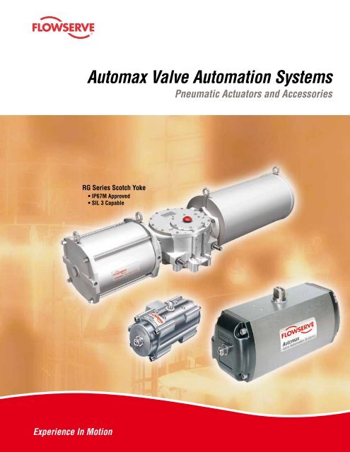
®flowserve.comAutomax Valve Automation SystemsPneumatic Actuators and AccessoriesRG Series Scotch Yoke• IP67M Approved• SIL 3 Capable1
- Page 2 and 3: Flow Control DivisionAutomax Valve
- Page 4 and 5: SuperNova B SeriesDouble ActingRack
- Page 7 and 8: flowserve.comThe MaxGuard process i
- Page 9 and 10: flowserve.comDimensionsMLL/2K/2.157
- Page 11 and 12: flowserve.comControls & Accessories
- Page 13 and 14: flowserve.comDimensionsModel ISOAJW
- Page 15 and 16: flowserve.comRG SeriesHeavy-Duty Sc
- Page 17 and 18: flowserve.comDimensionsLNFAABCJGEIN
- Page 19 and 20: flowserve.comDimensionsZDouble Acti
- Page 21 and 22: flowserve.comProduct Specification
- Page 23 and 24: flowserve.comActuator Model Designa
®flowserve.com<strong>Automax</strong> <strong>Valve</strong> <strong>Automation</strong> <strong>Systems</strong><strong>Pneumatic</strong> <strong>Actuators</strong> <strong>and</strong> AccessoriesRG Series Scotch Yoke• IP67M Approved• SIL 3 Capable1
Flow Control Division<strong>Automax</strong> <strong>Valve</strong> <strong>Automation</strong> <strong>Systems</strong>Flowserve Corporation’s<strong>Automax</strong> <strong>Valve</strong> <strong>Automation</strong><strong>Systems</strong> provides completevalve <strong>and</strong> damper automationto the worldwide processingindustries. We providemaximum value to theend user through a broadoffering of products,services, applicationengineering <strong>and</strong> oursystematic approachto automation.Quality, Dependability<strong>and</strong> ProductivityRecognized as the leader in valve automation systems, <strong>Automax</strong> pneumatic actuatorscan automate valves with torque values from 25 to 2.2 million in-lbs (2.8 - 248,566Nm).<strong>Actuators</strong> are available in a wide range of materials suitable for use in the mostdem<strong>and</strong>ing applications. Flowserve also offers a comprehensive range of NAMURControls <strong>and</strong> accessories such as lockout modules <strong>and</strong> gear overrides. To complete thepackage Flowserve can provide engineering design services for AutoBrakit Mountinghardware. To complete the package Flowserve can provide engineering design servicesfor automation mounting brackets, “AutoBrakit” <strong>and</strong> mounting hardware.2
flowserve.comSuperNovaSuperNova B Series Rack <strong>and</strong> Pinionactuators are designed for butterfly, plugor ball valves, <strong>and</strong> offer one compactdesign for double acting <strong>and</strong> springreturn. Precision die-cast pistons withlarge cylinder bearings increase efficiency<strong>and</strong> cycle life. Available in torque rangesfrom 25 to 58,000 in-lbs, for optimumactuator sizing.Controls & AccessoriesThe actuator is the heart of an automationsystem, but control accessories areimportant in creating a complete systemto meet increasingly sophisticatedcustomer requirements. Solenoid valves<strong>and</strong> related accessories with NAMURinterfaces provide direct, modularmounting on actuator. Switches,Positioners, Gear Overrides <strong>and</strong> LockoutModules can also be integrated into theassembly. <strong>Automation</strong> mounting brackets,“AutoBrakit” with mounting hardware areengineered to assure consistency <strong>and</strong>proper alignmentStainless SteelThe SXL ® Series utilizes a 316 Seriesstainless steel housing <strong>and</strong> is ideal foruse in corrosive environments. It isavailable in both double acting <strong>and</strong> springreturn <strong>and</strong> can be supplied with optionalstainless steel internals. For sanitary applicationsthe housing can be polished.Available in torque ranges from 78 to7279 in-lbs.Heavy-Duty RG Series RG1 - RG8A complete line of Scotch Yoke heavy-dutyactuators provides torques from 950 to2.2M in-lbs. The combination of ScotchYoke actuators plus Rack <strong>and</strong> Pinionactuators offers the opportunityto st<strong>and</strong>ardize on one source for yourcomplete quarter-turn automationneeds. Scotch Yoke actuators can alsobe configured with high pressurehydraulic cylinders.Page 4Page 11Page 12Page 14Sales <strong>and</strong> service facilitiesare strategically located inindustrial centers throughoutthe world.3
SuperNova B SeriesDouble ActingRack & Pinion <strong>Actuators</strong>are designed for automatingbutterfly, plug or ball valves<strong>and</strong> dampers. The actuatorsincorporate a precision-Broad size range offersoptimum actuatorsizing for each valverequirement.extruded hard anodizedaluminum body <strong>and</strong> aone-piece nitride-coatedpinion gear, factorylubricated for a longtrouble-free life. <strong>Actuators</strong>Upper <strong>and</strong> LowerPinion Bearingsextend life.Flats on Pinion Drive Shaftaccommodates wrenchoverrides <strong>and</strong> accessories.NAMUR Mounting Dimensionson actuator accessory holes<strong>and</strong> drive shaft.NAMUR MountingDimensionson actuator pneumaticport connections.are designed for 100-degreetravel with clockwise <strong>and</strong>counterclockwise traveladjustment for open <strong>and</strong>closed positions.4* Bidirectional travel stops are available via abottom-mounted Travel Stop Module onmodels SNA250 & SNA 300.Integral Travel Stopsin both directions with10 degrees of overtravelto assure precise adjustmentof both the open <strong>and</strong> closedpositions.*Dual ISO Mounting Padprovides ease <strong>and</strong> flexibilityin direct valve installation.Full Length GearEngagementbetween piston rack &nitride-coated pinion.Precision DieCast Pistonswith large cylinderbearings increaseefficiency <strong>and</strong>cycle life.
flowserve.comSuperNova B SeriesSpring ReturnThe most useful properties of the oxide coating are:• The oxide coating is integral with the base substrate <strong>and</strong>will prevent spalling from impact, thermal shock, or hightemperatures up to aluminum’s melting point. The oxidehas negligible effect on the other propertiesof aluminum.• Aluminum oxide is one of the hardest materials knownwith a hardness of corundum (45 to 65 Rockwell C).Further, abrasion tests show only half as much wear ashardened steel.• Aluminum oxide is relatively stable <strong>and</strong> chemically inert.The Oxide is usually stable over a pH range of 4.5 to 8.5but can be dissolved by strong acids <strong>and</strong> alkalis. Itnormally resists concentrated nitric acid at a pH 1 <strong>and</strong>ammonium hydroxide at pH 13, so consult factory forchemical compatibility.<strong>Automax</strong> Aluminum AlloyHard anodic oxidation is anelectrolytic conversionprocess which results inthe formation of an oxidefilm. Continuation of theprocess produces the “hard”One Compact Designfor double acting <strong>and</strong> springreturn is easily field convertibleby installing or removing springs.Field Reversibleaction simply byrotating pistons 180°.anodic coating to more than50µm. The chemical compositionprovides the optimumalloy for strength, abrasionresistance, cold working<strong>and</strong> chemical resistance.Corrosion Resistanthard anodized aluminum housingswith stainless steel fasteners.5
flowserve.comThe MaxGuard process is appliedto the actuator body <strong>and</strong> both endcaps providing an armored layer ofprotection – both internal <strong>and</strong>external.Recommended Applications:Acids / CausticsChemicalOffshoreWash downCoastal (Desalination)Specify MaxGuard for the following products:• SuperNova B050 – B200• SuperNova SNA250 – SNA3007
8Torque OutputsModelB050B063B085B100B115B125Note: For additional air supply pressures, consult factory oryour AutoSize software program.DA TorqueSpringAir Supply (psi)60 80 100No End Break End Break End Break End Break5 36 55 56 766 43 64 46 697 49 73 35 63 74 1028 61 92 15 49 54 88 93 1279 73 110 34 74 73 1136 68 102 103 1417 79 119 85 1288 90 136 66 1169 102 153 119 17510 113 170 100 16311 124 186 82 150 153 22212 135 203 135 2106 141 211 215 2937 164 246 177 2678 188 282 138 2419 211 317 248 36510 235 352 209 33911 258 387 171 313 320 46312 282 422 281 4376 260 390 397 5417 303 455 325 4938 347 520 253 4459 390 585 457 67310 433 651 385 62511 477 716 313 577 589 85312 520 781 518 8056 430 645 656 8947 502 753 537 8148 573 860 418 7359 645 968 756 111210 717 1075 637 103311 789 1183 518 954 975 141012 860 1290 856 13316 610 915 930 12677 712 1067 761 11558 813 1220 593 10429 915 1372 1071 157710 1017 1525 903 146411 1118 1677 734 1352 1381 199912 1220 1830 1213 1887ActuatorAir Pressure (psi)40 60 80 100 150A32 25 37 50 62 93B050 78 116 155 194 291B063 144 216 288 360 539B085 299 449 598 748 1122B100 552 828 1104 1380 2071B115 913 1369 1826 2282 3423B125 1294 1941 2588 3236 4853B150 2329 3494 4658 5823 8734B175 3487 5230 6974 8717 13076B200 4970 7455 9940 12424 18637SNA250 10354 15531 20707 25884 38826SNA300 15529 23293 31057 38822 58232SuperNova B SeriesAir Supply (psi)SpringModel60 80 100No End Break End Break End Break End Break6 1098 1648 1673 22807 1281 1922 1369 20788 1465 2197 1066 1875B150 9 1648 2471 1927 283710 1831 2746 1624 263511 2014 3020 1320 2432 2485 359712 2198 3295 2182 33946 1606 2527 2438 34577 1899 2907 2079 31338 2153 3349 1530 2851B175 9 2427 3759 2820 429210 2701 4170 2366 398911 2975 4581 1912 3686 3656 543012 3249 4992 3201 51276 2343 3516 3568 48647 2734 4107 2914 44328 3125 4691 2269 4000B200 9 3515 5277 4106 605310 3906 5865 3456 562211 4296 6451 2808 5190 5293 767412 4687 7037 4645 72436 2854 6591 7421 120257 3393 7690 6448 114418 3945 8788 5428 10857SNA250 9 4519 9887 4373 10273 9780 1545010 5106 10985 3274 9689 8566 1486611 5715 12084 7352 14281 12529 1945812 6343 13182 6138 13697 11314 188746 4744 11096 9931 174737 5640 12945 8245 165018 6558 14795 6482 15530SNA300 9 7512 16644 4658 14559 12669 2232610 8487 18493 2762 13588 10625 2135511 9500 20343 8581 20384 16348 2815012 10543 22192 6537 19412 14304 27179Spring Chart B050 2Spring Chart B063-B200Notes:Spring Combination 1Spring Group#1 Spring #2 Spring #3 Spring(inner) (low rate outer) (high rate outer)4 1 3 1 35 26 2 17 1 28 2 29 2 2Spring Combination 1Spring Group#1 Spring #2 Spring #3 Spring(inner) (middle) (outer)4 25 1 3 1 36 27 1 28 2 29 1 3 1 3 210 2 211 1 2 212 2 2 21#1 Spring has one color code dot2B050 has maximum of 2 springs per endcap3#2 Spring has two color code dots Install springs on opposite sides#3 Spring has three color code dots• All dimensions are in inches.• SNA250-SNA300 Spring Combinations – Spring number is total number of springs inendcaps. There should never be a difference in springs per endcap greater than one.Example: SNA250S09 would have four springs in one endcap <strong>and</strong> five in the other.
flowserve.comDimensionsMLL/2K/2.157CC1V A/F SQUAREK.16M6 x 12mm DP.S RADIUSB SQ.B 1 SQ.ORNP FOR CLEARANCEQ.945M5 x .32 DP.G NPT SUPPLY (CCW)F1.260G NPT SUPPLY (CW)A/2HJAModelNote:ISOA B B 1 GWeights (lbs) Volume (in) Cycle Time 3C C 1D E FH J K LN O P Q RDA&SR 180 SQ. SQ. NPT M 1, 2 DA SR CW CCW CW CCWB050 F04S11E 6.69 8.70 1.169 N/A #10-24x.31 N/A .433 .47 2.56 1/8 1.58 1.14 1.181 3.150 #10-24 .47 .394 .75 .79 .39 2.7 3.1 8.2 5.4 .5 .5B063 F03/F05S14E 7.95 9.92 1.392 1.002 1/4-20x.31 #10-24x.31 .551 .63 3.19 1/8 1.77 1.40 1.181 3.150 #10-24 .47 .394 .88 .79 .39 3.8 4.4 16 10 .5 .5B085 F05/F07S17E 9.84 12.13 1.949 1.392 5/16-18x.31 1/4-20x.31 .669 .75 4.15 1/8 2.24 1.87 1.181 3.150 #10-24 .77 .551 1.00 .79 .55 7.5 9.3 34 20 .5 .5B100 F05/F07S17E 11.65 14.80 1.949 1.392 5/16-18x.31 1/4-20x.31 .669 .75 4.80 1/4 2.48 2.17 1.181 3.150 #10-24 .77 .551 1.38 .79 .55 11.5 14.6 56 38 1 .5B115 F07/F10S22E 13.47 17.60 2.840 1.949 3/8-16x.39 5/16-18x.31 .866 .98 5.30 1/4 2.91 2.46 1.181 5.118 #10-24 1.10 .787 1.63 1.18 .79 17.7 22.5 94 65 1 1B125 F07/F10S22E 15.83 20.35 2.840 1.949 3/8-16x.39 5/16-18x.31 .866 .98 5.79 1/4 3.07 2.68 1.181 5.118 #10-24 1.10 .787 2.00 1.18 .79 23.8 30.2 128 90 1 1B150 F10/F12S27E 19.13 25.20 3.480 2.840 1/2-13x.45 3/8-16x.39 1.063 1.18 6.85 1/4 3.47 3.19 1.181 5.118 #10-24 1.87 1.417 2.38 1.18 .89 40.8 51.2 224 159 2.0 1.5B175 F10/F14S36E 21.34 28.58 3.897 2.840 5/8-11x.63 3/8-16x.39 1.417 1.57 8.21 1/4 4.17 3.74 1.181 5.118 #10-24 1.87 1.417 2.75 1.18 .89 63.7 77.2 351 232 3.0 2.0B200 F10/F14S36E 24.41 31.69 3.897 2.840 5/8-11x.63 3/8-16x.39 1.417 1.57 9.39 1/4 4.72 4.25 1.181 5.118 #10-24 1.97 1.417 2.94 1.18 .89 91.5 118 507 332 4.5 3.01Actuator shown in the full clockwise (CW) position as viewed from top.2Accessory mounting holes not for gear override or stop block.3Cycle times under no load conditions. Air line size, air capacity, <strong>and</strong> valve torque characteristics affect these cycle times.Faster or slower cycle times can be accomplished using special control components.• All dimensions are in inches.• Double Acting – Pressure at port “CW” will result in clockwise rotation. Pressure at port “CCW” will result in counter-clockwise rotation.• Spring Return – Pressure at port “CCW” will result in counterclockwise rotation. Springs provide clockwise rotation upon loss of pressure.How To Order (Select Bold Type Code from each column that applies)ModelB050B063B085B100B115B125B150B175B200SNA250SNA300TypeDSCM----Double ActingSpring Return (FCW)Spring Return (FCCW)180° Double ActingSprings (Select One)*050 Thru 300040506070809101112* Consult torque charts or AutoSize for applicable spring combinations.Example: A model B100 spring return (FCW) spring set 10 would be coded as B100S10.Seals Materials OptionsBlank -L -H -Buna (Std.)Low Temp.Viton (High Temp.)BlankKWGXM------Std. Hard Anodized AluminumK-Mass CoatedWhite Epoxy CoatedGray Epoxy CoatedBlackMax CoatingMaxGuard Severe ServiceActuatorR - Extra Long Travel StopC - Stainless Steel Pinion/ Snap Ring9
SuperNovaModels SNA250 & SNA300 90° <strong>and</strong> 180° <strong>Actuators</strong>DimensionsSNA250Typical 180° Rotary Actuator180° Rack & Pinion <strong>Actuators</strong><strong>Automax</strong> 180 Degree <strong>Actuators</strong> areavailable in the same models <strong>and</strong> withthe same torque outputs as thest<strong>and</strong>ard SuperNova Double Actingactuators. The integral mechanical,end-of-stroke travel adjustment is forone direction only. As options, travelstops can be furnished for less than180° travel <strong>and</strong> an additional travel stopfor the other direction can be providedin the valve actuator adaption.<strong>Automax</strong> has developed economicalcontrol circuits <strong>and</strong> devices toactuate multiport valves both2 position (0°,180°) <strong>and</strong>3 position (0°, 90°,180°)utilizing the UltraSwitch. Consult your<strong>Automax</strong> Representative forassistance in selecting the bestcontrol package.Dimensions for 50-200 size 180°actuators on previous page.ModelAHWeights (lbs) Volume (in) Cycle TimeB 1 C D E F GJ K M 2,3 O P PP Q R SDA&SR 180 NPT DA SR CW CCW CW CCWSNA250 27.32 39.14 4.250 5/8-11X.63 2.87 1.850 1.81 11.02 1/2 5.91 11.02 5.118 2.20 1.969 0.98 3.75 1.65 .24 137 172 757 720 5-7 5-7SNA300 32.60 44.00 5.000 5/8-11X.94 N/A N/A 2.50 13.39 1/2 6.30 13.39 5.118 2.44 1.969 0.98 3.75 1.65 N/A 217 288 1403 1019 6-9 6-910Notes:1Actuator shown in the full clockwise (CW) position as viewed from top.2Accessory mounting holes not for gear override or stop block.3Use studs only to mount. Bolts not recommended.For “How To Order”see page 13• All dimensions are in inches.• Cycle times under no load conditions. Air line size, air capacity, <strong>and</strong> valve torquecharacteristics affect these cycle times. Faster or slower cycle times can beaccomplished using special control components.
flowserve.comControls & AccessoriesControlsS25N Directional <strong>Valve</strong>*The <strong>Automax</strong> Directional <strong>Valve</strong> mountsdirectly to SuperNova series actuatorswhich eliminates the cost of tubing<strong>and</strong> fittings. The valves are availablefor double acting <strong>and</strong> spring returnactuators with NEMA 4X, 7 & 9, orintrinsically-safe <strong>and</strong> low powersolenoid operators. These valveshave been tested <strong>and</strong> proven reliablefor over 1 million cycles.APS1 Module*The <strong>Automax</strong> APS1 module workswith the <strong>Automax</strong> S25N solenoidvalve <strong>and</strong> diverts exhaust air frombetween the pistons into the springchamber. This prevents corrosiveatmospheres from being pulled intothe spring chamber.APS2 Module*The <strong>Automax</strong> APS2 module workswith remote/line mounted solenoidvalves <strong>and</strong> diverts exhaust air frombetween the pistons into the springchamber. This prevents corrosiveatmospheres from being pulled intothe spring chamber.LV1 Lockout & Vent <strong>Valve</strong>*The LV1 Lockout <strong>and</strong> Vent <strong>Valve</strong>module provides two primaryfunctions. The LV1 may be used witha manual override to shut off supplyair <strong>and</strong> vent actuator ports. The LV1may also be used as a pneumaticlockout valve which, when properlyimplemented, will satisfy OSHASt<strong>and</strong>ard 1910.47. The LV1 maybe s<strong>and</strong>wich mounted with other<strong>Automax</strong> NAMUR accessories ormay be used with the NPT1 adaptor.FC1, FCDA & FCSR*The ‘FC’ Series Flow Control modulesprovide compact flow controls forprecise adjustment of SuperNovaactuator speeds. The Flow ControlModules may be s<strong>and</strong>wich mountedwith other <strong>Automax</strong> accessories ormay be used with the NPT1 adaptor.* Consult individual catalogs <strong>and</strong> IOMs for additional informationAccessories“Pharos” NAMUR Indicator*Provides an economical solution forpositive visual indication of the actuatorposition. Constructed of tough industrialengineered resin, the UltraIndicator canbe used on actuators that utilize aNAMUR mounting interface.UltraSwitch GL/XCL/PL Series RotaryPosition Indicators*The UltraSwitch series of positionindicators provides a compact <strong>and</strong>economical package for both visual<strong>and</strong> remote electrical indication of valveposition. Models are available in bothdie cast aluminum <strong>and</strong> non-metallicversions. Suitable for non-hazardous,hazardous <strong>and</strong> intrinsically-safeapplications.Aviator II <strong>and</strong> BUSwitch RotaryPosition Indicator with InternalPilot Solenoid*The Aviator rotary position indicatorenclosure with internal pilot solenoidcoil provides a truly integrated package.It can easily be converted to a BUSwitchby simply adding a Fieldbus communicationprinted circuit board.APEX Modular Positioner*Epoxy coated aluminium construction,the Apex positioner combines precisevalve positioning with advanced features.A modular manifold base allows 3-15 psipneumatic control signals, or 4-20 mAsignals with the addition of the I/Pmodule. Models are available forcorrosion resistant applications <strong>and</strong>hazardous locations as defined by UL,C-UL, ATEX, <strong>and</strong> SAA.Lockouts*The lockout option permits easy lockoutof automated valves. Lockouts aredesigned to withst<strong>and</strong> the rated outputtorque of the actuator, with the intentto meet the requirements of OSHASt<strong>and</strong>ard 1910.47 “The Control ofHazardous Energy” (Lockout/Tagout.)Gear Overrides*Declutchable gear overrides are optionswhich allow local manual control ofactuated valves <strong>and</strong> dampers. The gearoverrides are sized for easy operation<strong>and</strong> can be combined with other controlaccessories.AutoBrakits*<strong>Automax</strong> heavy-duty mounting kits aredesigned to close tolerances to assureconsistency <strong>and</strong> proper alignment,which are essential to ensuremaximum actuator <strong>and</strong> valvecycle life.11
SXL SeriesStainless SteelThe SXL Series utilizes a316 Series stainless steelbody <strong>and</strong> is ideal for usein corrosive environments.SXL SeriesThe SXL Series is available in bothDouble Acting <strong>and</strong> Spring Returnversions with a maximum doubleacting torque output of 7,279 in-lbs.It can be supplied with stainless steelor aluminum pistons <strong>and</strong> springs percustomer requirements <strong>and</strong> is alsoavailable with optional polished finishesfor sanitary applications.Full Length GearEngagementbetween piston rack& stainless steel pinion.Pinion Bearingslocated at the top <strong>and</strong>bottom of the pinion,eliminate potential galling.Flats on Pinion Drive Shaftaccommodates manualoverrides <strong>and</strong> accessories.NAMURmounting dimensionson actuator accessoryholes <strong>and</strong> drive shaft.NAMURmounting dimensionson actuator pneumaticport connections.Integral Travel Stopsin both directions with 10 degreesof overtravel to assure preciseadjustment of both open <strong>and</strong>closed positions.Precision Die Cast Pistonswith large cylinder bearings increasesefficiency <strong>and</strong> cycle life. Field reversibleaction simply by rotating pistons 180°.(Optional stainless steel pistonsalso available.)ISOmounting dimensions onactuator to valve interface.Air Purge Modulesare available in stainless steel to isolatethe internal components of springreturn actuators from the atmosphere.Stainless steel breather vent optional.12
flowserve.comDimensionsModel ISOAJWeights (lbs) Volume (in) Cycle TimeB 1 C D E F G HK M 2, 3 0 P Q RSQUARE NPT DA SR CW CCW CW CCWSXL050 FO4S11M 6.69 1.169 M5 x .31 .433 .47 .79 2.56 1/8 1.85 1.18 3.150 .56 .39 .83 .39 4.85 5.15 8.2 5.4 .5 .5SXL063 FO5S14M 7.95 1.392 M6 x .31 .551 .63 .79 2.56 1/8 2.11 1.44 3.150 .56 .39 .91 .39 7.05 7.80 16 10 .5 .5SXL085 FO7S17M 9.84 1.949 M8 x .31 .669 .79 .79 3.94 1/8 2.60 1.87 3.150 .77 .55 1.18 .55 11.24 13.18 34 20 .5 .5SXL100 FO7S17M 11.65 1.949 M8 x .31 .669 .79 .79 4.57 1/4 2.95 2. 3.150 .77 .55 1.46 .55 16.09 19.02 56 38 1 .5SXL115 F1OS22M 13.46 2.840 M10 x .31 .866 .98 1.18 5.16 1/4 3.23 2.46 5.118 1.38 .79 1.77 .79 23.14 27.55 94 65 1 1SXL125 F1OS22M 15.83 2.840 M10 x .31 .866 .98 1.18 6.61 1/4 3.43 2.70 5.118 1.38 .79 2.17 .79 38.14 45.12 128 90 1 1SXL150 F12S27M 19.13 3.480 M12 x .47 1.063 1.14 1.18 6.61 1/4 3.94 3.19 5.118 1.97 .89 2.64 1.42 51.14 61.50 224 159 2 1.5Notes:1Actuator shown in the full clockwise (CW) position as viewed from top.2Accessory mounting holes not for gear override or stop block.3Use studs only to mount. Bolts not recommended.How To Order (Select Bold Type Code from each column that applies)ModelSXL050SXL063SXL085SXL100SXL115SXL125SXL150TypeDSC---Double ActingSpring Return (FCW)Spring Return (FCCW)Springs (Select One)*050 Thru 300040506070809101112Example: A model SXL100 spring return (FCW) spring set 10 would be coded as SXL100S10.• All dimensions are in inches.• Cycle times under no load conditions. Air line size, air capacity, <strong>and</strong> valve torquecharacteristics affect these cycle times. Faster or slower cycle times can beaccomplished using special control components.Seals Materials OptionsBlank -L -Viton (Std.)Low Temp.BlankKF---Std. Hard Anodized AluminumK-Mass CoatedPolishedR - Extra Long Travel StopM -Stainless Steel SpringsP -Stainless Steel Pistons13
RG SeriesHeavy-Duty Scotch Yoke ActuatorThe <strong>Automax</strong> RG Seriesprovides up to 2.2 millionin-lbs of heavy-duty Scotchyoke torque. Enhancedperformance is achieved byusing a superior yokesupport system that significantlyreduces transverseloads.Guide B<strong>and</strong>sOptimizes piston support <strong>and</strong>extends Quad Seal life withprotective wiping action.Piston SealsDynamic Quad Seal design providesenhanced cycle life versus conventionalO-Rings.Features• True Modular Design• On-Off, Multi-Position <strong>and</strong> Throttling• <strong>Pneumatic</strong>, Gas <strong>and</strong> Hydraulic Models• Spring Return “Fail Safe” <strong>and</strong>Double ActingModular ConstructionThe Pressure, Torque <strong>and</strong> Spring Modulesare designed for maximum flexibility,reduced envelope dimensions <strong>and</strong> weight.• Torque Outputs:• DA – 2.2M in-lbs (248K Nm)• SR – 1.2M in-lbs (124K Nm)• Operating Pressures:• <strong>Pneumatic</strong>: 40-150psi• Hydraulic: 500-3000psiIP67M Ingress ProtectionO-Rings or dynamic quad seals are utilized toconform to IP67M specifications, ensuringoptimal ingress protection.14CylinderHeavy wall cylinders provide increased “job site”durability. Interior surface is honed <strong>and</strong> hardchrome plated to provide superior corrosion <strong>and</strong>wear resistance.Scotch YokeSymmetrical or canted ductile ironcast yoke. Enclosed yoke slot forincreased strength with 2 keywayssupporting parallel or perpendicularmounting.Rod BearingsPTFE lined metal reinforced bronzebearings provide superior piston rodsupport, extending cycle life
flowserve.comRG SeriesHeavy-Duty Scotch Yoke Actuator20% higher break torqueInterchangeable Yoke SystemSymmetrical YokeFeatures• Hard Chrome Plated Cylinder Walls• Symmetrical <strong>and</strong> Canted Yoke• Guide Bar Yoke Support• Dual DD Cylinder OptionCanted Yoke• Field Reversible Action• Overrides, Line Break <strong>and</strong> Special Controls• ESD Performance• Ductile iron casting• Totally enclosed yoke slot forincreased strength <strong>and</strong> cyclelife• Canted yoke results in approx.20% higher break torque• 2 keyway provision for flexibilityof parallel orperpendicular mountingOverride OptionsSpring Module design facilitates field retrofittingof jackscrew or hydraulic overridesSlider BlockInduction hardened <strong>and</strong> hard chromeplated yoke pin with aluminum bronzeslider blocks minimize contact stress<strong>and</strong> ensure high cycle life.Steel Guide BarHard chrome plated alloysteel guide bar providesoptimal support of thetransverse loads.Spring ModulePull-to-compress, concentric-nesteddesign utilizes high strength alloyspring steel to maintain consistenttorque output (over time) <strong>and</strong> promotehigh cycle life performance.Pull RodSpring pull rod is over-sized to resist impactloads <strong>and</strong> hard chrome plated to providesuperior corrosion <strong>and</strong> wear resistance.Bidirectional Travel StopsAllow precise adjustment of open <strong>and</strong>closed positions, ensuring valve shutoff<strong>and</strong> optimizing seat life.Torque ModuleModular with symmetrical flanges <strong>and</strong> female outputdrive. Provided with dual accessory mounting pads<strong>and</strong> compliant to international ISO/MSS <strong>and</strong> NAMURmounting specifications15
AccessoriesRG SeriesHeavy-Duty Scotch Yoke ActuatorModular Construction• Double Acting or Spring Return (FCW or FCCW)• <strong>Pneumatic</strong> or Hydraulic Pressure Modules• Torque Module with symmetrical or canted yokes• Override Options – Direct Drive Jackscrew, Bevel GearJackscrew or Hydraulic OverrideSR with DirectDrive JackscrewDA with HydraulicOverride CylinderDA EndplateDD Double Acting Dual CylinderDA Direct Drive JackscrewDA Bevel Gear Jackscrew<strong>Pneumatic</strong> Pressure ModuleDA Hydraulic OverrideSR Spring ModuleHydraulic Pressure ModuleSR Direct Drive JackscrewSR Bevel Gear JackscrewSR Hydraulic Override16
flowserve.comDimensionsLNFAABCJGEINPT Air PortsSpring ReturnGSide ViewBKANABAMNABDGYY1GDouble Acting Dual CylinderActuator Dimensions, mm (inch)SERIES A B C D E F I J K L M N X Y Y1RG1141 310 498 18,5 264 55 99 129 610,5 1090 902 282 68 60 30(5.55) (12.20) (19.61) (0.73) (10.39) (2.17) (3.90) (5.08) (24.04) (42.91) (35.51) (11.10) (2.68) (3.36) (1.18)RG2162 368 586 20 322 65 116 144 712 1278 1060 324 68 60 30(6.38) (14.49) (23.07) (0.79) (12.68) (2.56) (4.57) (5.67) (28.03) (50.31) (41.73) (12.76) (2.68) (3.36) (1.18)RG3175 444 706 23 380 75 111 151 817 1500 1238 350 95 52 13(6.98) (17.48) (27.80) (0.91) (14.96) (2.95) (4.37) (5.94) (32.17) (59.06) (48.74) (13.78) (3.74) (2.05) (0.51)RG4243 565 868 23 467 91 145 175 1074 1919 1616 486 95 60 30(9.57) (22.24) (34.17) (0.91) (18.39) (3.58) (5.71) (6.89) (42.28) (75.55) (63.62) (19.13) (3.74) (3.36) (1.18)RG5312 716 1008 26 568 145 175,5 189,5 1366 2348 2056 624 95 60 30(12.28) (28.19) (39.69) (1.02) (22.36) (5.71) (6.91) (7.46) (53.78) (92.44) (80.94) (24.57) (3.74) (3.36) (1.18)RG6394 756 1640 28 600 185 208 218 1572 3184 2300 788 95 60 30(15.51) (29.76) (64.57) (1.10) (23.62) (7.28) (8.19) (8.58) (61.89) (125.35) (90.55) (31.02) (3.74) (3.36) (1.18)RG7500 810 2030 50 615 220 265 310 1860 3840 2620 1000 95 100 30(19.69) (31.89) (79.92) (1.97) (24.21) (8.66) (10.43) (12.20) (73.23) (151.18) (103.18) (39.37) (3.74) (3.94) (1.18)RG8665 860 2600 55 680 280 306 360 2245 4790 3050 1330 95 100 30(26.18) (33.86) (102.36) (2.17) (26.77) (11.02) (12.05) (14.17) (88.39) (188.58) (120.08) 52.36) (3.74) (3.94) (1.18)Cylinder Size 5" 6" 7" 8" 9" 10" 12" 14" 16' 18" 20" 22" 24" 28" 32" 36" 40"GNPT Air Ports178(7.01)Double Acting Single Cylinder178(7.01)196(7.72)Z222(8.74)X248(9.76)274(10.79)324(12.76)375(14.76)438(17.24)486(19.13)532(20.94)588(23.15)648(25.51)865(34.06)967(38.07)1069(42.09)1170(46.06)Port Size NPT 3/8˝ 3/8˝ 3/8˝ 3/8˝ 3/8˝ 1/2˝ 3/4˝ 3/4˝ 3/4˝ 1˝ 1˝ 1˝ 1˝ 1½˝ 1½˝ 1½˝ 2˝17
DimensionsISO BASE DETAILS(RG1, RG2)SIDE VIEWISO BASE DETAILS(RG3 to RG6)SIDE VIEWISO BASE DETAILS(RG7)SIDE VIEWISO BASE DETAILS(RG8)SIDE VIEW18Mounting Base Details & Dimensions, mm (inch)SERIES ISO BASE SPIGOT Ø PCD BORE Ø BORE Tol W W Tol No of Bolt X Size T U U TolRG1 F14100 140 48145 51,8H9+0.12/+0.05 4 X M16(3.94) (5.51) (1.89)(0.55)(0.20) (2.04)+0.2/+0.0RG2 F16130 165 60185 64,4H9+0.15/+0.07 4 X M20(5.12) (6.50) (2.36)(0.71)(0.20) (2.54)+0.2/+0.0RG3 F25200 254 72205 76,9H9+0.15/+0.07 8 X M16(7.87) (10.0) (2.83)(0.79)(0.20) (3.03)+0.2/+0.0RG4 F30230 298 98285 104,4H9+0.15/+0.07 8 X M20(9.06) (11.73) (3.86)(1.10)(0.20) (4.11)+0.2/+0.0RG5 F35260 356 160405 169,4H9+0.18/+0.08 8 X M30(10.24) (14.02) (6.30)(1.57)(0.20) (6.67)+0.2/+0.0RG6 F40300 406 180458 190,4H9+0.18/+0.08 8 X M36(11.81) (15.98) (7.09)(1.77)(0.20) (5.50)+0.2/+0.0RG7 F48370 483 220508 231,4H9+0.18/+0.08 12 X M36(14.57) (19.02) (8.66)(1.97)(0.20) (9.11)+0.3/+0.0RG8 F60470 603 280638 292,4H9+0.22/+0.10 20 X M36(18.5) (23.74) (11.02)(2.48)(0.20) (11.51)+0.3/+0.0
flowserve.comDimensionsZDouble Acting Single CylinderDimension Z, mm (inch)SERIES 5" 6" 7" 8" 9" 10" 12" 14" 16' 18" 20' 22" 24" 28" 32" 36" 40"10 10 1 12 25 38 63RG1– – – – – – – – – –(0.39) (0.39) (0.04) (0.47) (0.98) (1.50) (2.48)5 8 21 46 71,5 103RG2 – – –– – – – – – – –(0.20) (0.31) (0.83) (1.81) (2.81) (4.06)26 51 76,5 108 132 155RG3 – – – – –– – – – – –(1.02) (2.01) (3.01) (4.25) (5.20) (6.10)42,5 74 98 121 149 179RG4 – – – – – – –– – – –(1.67) (2.91) (3,86) (4.76) (5.87) (7.05)43,5 67,5 90,5 118,5 148,5 257RG5 – – – – – – – –– – –(1.71) (2.66) (3.56) (4.67) (5.85) (10.12)35 58 86 116 224,5 275,5 326,5RG6 – – – – – – – – ––(1.38) (2.28) (3.39) (4.57) (8.84) (10.85) (12.85)59 167,5 218,5 269,5 320RG7 – – – – – – – – – – – –(2.32) (6.59) (8.6) (10.61) (12.60)177,5 228,5 279RG8 – – – – – – – – – – – – – –(6.99) (9.00) (10.98)LNBAACGEDouble Acting T<strong>and</strong>em CylinderDimensions for Spring Return T<strong>and</strong>em Cylinders, mm (inch)SERIES A B C E G N LRG8 32-3266517152600680117013305645(26.18)(67.52)(102.36)(26.77)(46.06)52.36)(222.24)RG836-3666517402600680117013305670(26.18)(68.50)102.36)(26.77)(46.06)52.36)(223.23)19
Module WeightsModel TorqueModuleRG1RG2RG3RG4RG5RG6RG7RG868(31)99(45)143(65)295(134)510(231)933(423)1881(853)3718(1686)Module Weights, Lbs (kgs)Pressure ModuleSpring Module5 6 7 8 9 10 12 14 16 18 20 22 24 28 32 36 40 1 2 3 4 5 6 7 831(14)35(16)47(22)– – –53(24)56(25)66(30)69(32)– – – – –94(43)99(45)100(45)139(63)143(65)142(64)– – – – – – –– – – – – – – – – –209(95)200(91)217(99)– – – – – – – –320(145)318(145)339(154)356(162)– – – – – – – – –– – – – – – – –406(185)427(194)455(207)493(224)561(255)586(266)610(277)616(280)– – – – – –741(337)853(388)861(391)– – – – – – – – – – – – –– – – – – – – – – – – – –942(428)994(452)1051(478)– – – –1634(743)1732(787)1824(829)2165(984)– – –88(40)128(58)226(103)402(183)639(290)97(44)145(66)260(118)442(201)737(335)101(46)154(70)267(121)462(210)770(350)103(47)158(72)269(122)477(217)783(356)106(48)158(72)276(125)510(232)901(410)114(52)172(78)330(150)545(248)955(434)2321 3044 1283 1738 1671 1730 2061 1995–(1055)(1384)(583) (790) (760) (787) (937) (907)2411 3156 3913 2283 2946 3043 3177 3630 3709(1096)(1435)(1779)(1038)(1339)(1383)(1444) (1650)(1686)2819 3372 4159 4627 5800 6113 6227 7111 7423(1282)(1533)(1891 (2103)(2637)(2779)(2830) (3232) (3374)119(54)180(82)321(146)565(257)119(54)186(85)–581(254)– –– –– –– –NAMUR shaft height <strong>and</strong> bracket mounting detailsO8040SQ. 19Detail B15 30308X Ø 4.20 ↓ 13.00M5 - 6H ↓ 10.00Series ORG1 -RG2 -RG3 -RG4 130RG5 130RG6 130RG7 130RG8 130Detail C20
flowserve.comProduct Specification• Actuator shall be designed in accordance with EN15714-3 to define minimum cycle life performance <strong>and</strong> designed for on-off <strong>and</strong>modulating service.• Actuator output shall meet ISO rated torque compliance to provide safe mounting interface <strong>and</strong> comply with ISO 5211/MSS SP-101mounting st<strong>and</strong>ards <strong>and</strong> NAMUR VDI/VDE st<strong>and</strong>ards for accessory mounting.• Actuator shall have a symmetrical torque module to simplify field service <strong>and</strong> interchangeability of spring <strong>and</strong> air modules. Manualoverrides <strong>and</strong> mounting is consistent for both spring <strong>and</strong> torque module to simplify mounting.• The actuator torque module shall utilize an interchangeable yoke system to allow simple field conversion of symmetrical <strong>and</strong> cantedyokes.• The spring module shall use a pull-to-compress motion with single or concentric-nested springs that are internally supported <strong>and</strong>guided <strong>and</strong> weld secured for safety.• The spring module shall be designed for minimum length <strong>and</strong> weight to improve the center of gravity, reduce material stress <strong>and</strong>assembly support requirements.• The actuator shall have hard chrome plated cylinder walls to provide superior corrosion <strong>and</strong> wear resistance.• The actuator piston sealing should use advanced Quad Seal technology to provide enhanced cycle life compared to conventionalO-Rings.• The internal support guide rods, spring rods <strong>and</strong> piston rods shall be hard chrome plated for superior corrosion <strong>and</strong> wear resistance.• The pneumatic cylinder shall use external retention rods to provide visual confirmation <strong>and</strong> inspection of rod integrity for increasedsafety.Agency & Environmental Approvals• IP67M (1 meter depth for 30 minutes)• IEC 61508 SIL 3 Suitable• ATEX CertifiedSt<strong>and</strong>ard Paint SpecificationThe st<strong>and</strong>ard external surface treatment consists of a 2 pack primer <strong>and</strong> 2 pack epoxy coating. This international marine coating is suitablefor chemical, coastal <strong>and</strong> offshore environments providing superior corrosion resistance.Primer Coat: Akzo Nobel Intergard 251, anticorrosive zinc phosphate epoxy primer, 75 microns DFT, color: KGA902-Red.Top Coat: Akzo Nobel Intergard 740 epoxy finish, 2 mills DFTFinished Color: ECK724 – Storm Grey, High Gloss21
Manual Override OptionsJackscrewHydraulicS<strong>and</strong>wich GearBevel GearTorque DA SRModelISOMountingN-min-lbDirectOperationJackscrewBevelGearS<strong>and</strong>wichDeclutchableGearHydraulicDirectOperatorJackscrewBevelGearS<strong>and</strong>wichDeclutchableGearHydraulicRG1 F14 2000 17702 – – – –RG2 F16 4000 35404 – – – –RG3 F25 8000 70808 RG4 F30 16000 141616 – – RG5 F35 32000 283232 – – RG6 F40 63000 557613 – – – – – – RG7 F48 125000 1106375 – – – – – – RG8 F60 250000 2212750 – – – – – – 22
flowserve.comActuator Model DesignationHow to OrderSeriesBodySizeCylinder SizeActionSpringModuleTorque Pattern(Yoke)Sealing/Temp Manual Override Material/ Coatings Options1 05 06 07 08 09 10 12 DA- Double Acting Single Cylinder 0 S- Symmetrical N- Nitrile, 0- None GE- Grey Epoxy (std) 00- None-20˚ F to 180˚ F2 08 09 10 12 14 16 DD- Double Acting Dual Cylinder 1 C- Canted G- S<strong>and</strong>wich Declutch Gbox PO- Primer Only TC- Ext. Stopper -CW3 10 12 14 16 18 20 2 H- High Temp J- Jackscrew WE- White Epoxy TO- Ext. Stopper -CCW4 14 16 18 20 22 24 3(Viton),0˚ F to 300˚ F D- Bevel Gear Jackscrew SP- Specials TB- Ext. Stopper -Both DirRG5 16 18 20 22 24 28 4 L- Low Temp, H- Hydraulic S xxx- Specials code(material)6 18 20 22 24 28 32 36 SR- Spring Return Fail CW 5-55˚ F to 180˚F7 24 28 32 36 40 SO- Spring Return Fail CCW 68 28 32 36 40 78Model Code Example:RG 5 22 SR 6 C N D GE TCTo Access Literature OnlineEvery item in this catalog has a brochure containinga great deal of technical product detail. It’s easy tofind… it’s free… <strong>and</strong> you do not need a password.Do This:➊ Go to www.flowserve.com➋ Click in the box thatsays “Literature”➌ Enter keyword orliterature number➍ Click on “Search"The most recent version of each product bulletin will beavailable on this site.Once you have the PDF, you can: • read it• print it• download it• even e-mail it23
<strong>Automax</strong> <strong>Valve</strong><strong>Automation</strong> <strong>Systems</strong>Rotary Switches <strong>and</strong>Positioners• Workhorse• High Reliability• Hostile Environments• UL, FM, CSA <strong>and</strong> ATEXCenelec Approvals• Metallic <strong>and</strong> Non-metallicHousings• Pharos VisualIndication Option• Fieldbus Communications• Multiple Switch OptionsFlowserve Corporation has established industry leadership in the design <strong>and</strong> manufacture of its products. When properly selected this Flowserve product is designed to perform its intended function safely during its useful life. However, the purchaseror user of Flowserve products should be aware that Flowserve products might be used in numerous applications under a wide variety of industrial service conditions. Although Flowserve can (<strong>and</strong> often does) provide general guidelines, it cannotprovide specific data <strong>and</strong> warnings for all possible applications. The purchaser/user must therefore assume the ultimate responsibility for the proper sizing <strong>and</strong> selection, installation, operation, <strong>and</strong> maintenance of Flowserve products. The purchaser/user should read <strong>and</strong> underst<strong>and</strong> the Installation Operation Maintenance (IOM) instructions included with the product, <strong>and</strong> train its employees <strong>and</strong> contractors in the safe use of Flowserve products in connection with the specific application.While the information <strong>and</strong> specifications contained in this literature are believed to be accurate they are supplied for informative purposes only <strong>and</strong> should not be considered certified or as a guarantee of satisfactory results by reliance thereon.Nothing contained herein is to be construed as a warranty or guarantee, expressed or implied, regarding any matter with respect to this product. Because Flowserve is continually improving <strong>and</strong> upgrading its product design, the specifications,dimensions <strong>and</strong> information contained herein are subject to change without notice. Should any question arise concerning these provisions, the purchaser/user should contact Flowserve Corporation at any one of its worldwide operations or offices.Flowserve CorporationFlow Control Division1978 Foreman DriveCookeville, Tennessee 38501 USAPhone: +931 432 4021Fax: +931 432 5518www.flowserve.comFlowserve CorporationFlow Control Division1350 North Mountain Springs ParkwaySpringville, Utah 84663-0913 USAPhone: +801 373 3028Fax: +801 489 2228Flowserve Pte LtdNo. 12 Tuas Avenue 20Singapore 638824Phone: +65 6879 8900Fax: +65 6862 4940Flowserve Flow Control (UK) Ltd.Burrell RoadHaywards HeathWest Sussex United KingdomRH16 1TLPhone: +44 1444 314400Fax: +44 1444 314401<strong>Automax</strong>Im groß Rohr 2Limburg, Hessen 65549GermanyPhone: +49 (0)6431 96610Fax: +49 (0)6431 966130Flowserve Ahaus GmbHvon-Braun-Str. 19a48683 AhausPhone: +49 2561 686-119Fax: +49 2561 686-109Flowserve Flow Control GmbH<strong>Actuators</strong> <strong>and</strong> <strong>Automation</strong> CenterGermanyRudolf Plank Str. 2D-76275 EttlingenGermanyPhone +49 (0)7243 103 0Fax +49 (0)7243 103 222Flowserve Flow Control Benelux BVRechtzaad 174703 RC Roosendaal NBNetherl<strong>and</strong>sPhone: +31 165 598 800Fax: +31 165 555 670Flowserve Australia Pty LtdFlow Control Division14 Dalmore DriveScoresby, Victoria 3179AustrialiaPhone: +61 3 9759 3300Fax: +61 3 9759 3301Flowserve S.R.LVia Prealpi 30Cormano MI Italy I - 20032Phone: +39 02 663251Fax: +39 02 6151863Flowserve do Brasil LtdaRua Tocantins, 128 - Bairro Nova GertiSão Caetano do Sul,São Paulo 09580-130 BrazilPhone: +5511 4231 6300Fax: +5511 4231 6329 - 423Unit 01\02\06\07 9FChina Fortune TowerNo. 1568, Century Avenue, PudongShanghai China 200122Phone: +86 21 38654800Fax: +86 21 50811781Flowserve CorporationNo. 35, Baiyu RoadSuzhou Industrial ParkSuzhou 215021, Jiangsu Province,PRCPhone: +86-512-6288-1688Fax: +86-512-6288-873724FCD AXENBR0005-04 04/11 Printed in U.S.A. © Flowserve Corporation


