Download Barton 228C Differential Pressure ... - Proflow Systems
Download Barton 228C Differential Pressure ... - Proflow Systems
Download Barton 228C Differential Pressure ... - Proflow Systems
- No tags were found...

Create successful ePaper yourself
Turn your PDF publications into a flip-book with our unique Google optimized e-Paper software.
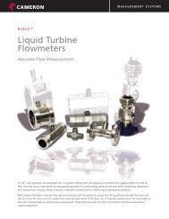
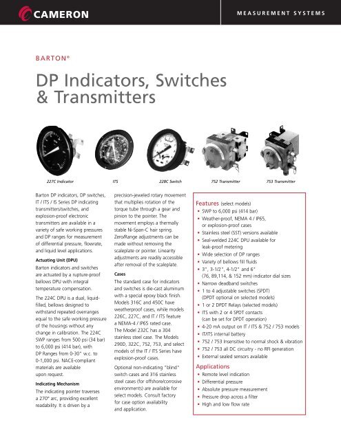
MEASUREMENT SYSTEMSBARTON ®DP Indicators, Switches& Transmitters227C Indicator ITS <strong>228C</strong> Switch752 Transmitter 753 Transmitter<strong>Barton</strong> DP indicators, DP switches,IT / ITS / IS Series DP indicatingtransmitters/switches, andexplosion-proof electronictransmitters are available in avariety of safe working pressuresand DP ranges for measurementof differential pressure, flowrate,and liquid level applications.Actuating Unit (DPU)<strong>Barton</strong> indicators and switchesare actuated by a rupture-proofbellows DPU with integraltemperature compensation.The 224C DPU is a dual, liquidfilled,bellows designed towithstand repeated overrangesequal to the safe working pressureof the housings without anychange in calibration. The 224CSWP ranges from 500 psi (34 bar)to 6,000 psi (414 bar), withDP Ranges from 0-30" w.c. to0-1,000 psi. NACE-compliantmaterials are availableupon request.Indicating MechanismThe indicating pointer traversesa 270° arc, providing excellentreadability. It is driven by aprecision-jeweled rotary movementthat multiplies rotation of thetorque tube through a gear andpinion to the pointer. Themovement employs a thermallystable Ni-Span-C hair spring.Zero/Range adjustments can bemade without removing thescaleplate or pointer. Linearityadjustments are readily accessibleafter removal of the scaleplate.CasesThe standard case for indicatorsand switches is die-cast aluminumwith a special epoxy black finish.Models 316C and 450C haveweatherproof cases, while models226C, 227C, and IT / ITS featurea NEMA-4 / IP65 rated case.The Model 232C has a 304stainless steel case. The Models290D, 322C, 752, 753, and selectmodels of the IT / ITS Series haveexplosion-proof cases.Optional non-indicating "blind"switch cases and 316 stainlesssteel cases (for offshore/corrosiveenvironments) are available forselect models. Consult factoryfor case option availabilityand application.Features (select models)• SWP to 6,000 psi (414 bar)• Weather-proof, NEMA 4 / IP65,or explosion-proof cases• Stainless steel (SST) versions available• Seal-welded 224C DPU available forleak-proof metering• Wide selection of DP ranges• Variety of bellows fill fluids• 3", 3-1/2", 4-1/2" and 6"(76, 89,114, & 152 mm) indicator dial sizes• Narrow deadband switches• 1 to 4 adjustable switches (SPDT)(DPDT optional on selected models)• 1 or 2 DPDT Relays (selected models)• ITS with 2 or 4 SPDT contacts(can be set for DPDT operation)• 4-20 mA output on IT / ITS & 752 / 753 models• IT/ITS internal battery• 752 / 753 Insensitive to normal shock & vibration• 752 / 753 all DC circuitry - no RFI generation• External sealed sensors availableApplications• Remote level indication• <strong>Differential</strong> pressure• Absolute pressure measurement• <strong>Pressure</strong> drop across a filter• High and low flow rate
DPU DetailsModel 224C (Dual Bellows)The 224C DPU is a lightweight compact sensor thatincorporates a rupture-proof bellows in a common-headdesign housing. It has an exceptionally fast response time, isself-draining, and has built-in temperature compensation.The 224C DPU consists of a Bellows Unit Assembly (BUA) andremovable pressure housings. Within the BUA, flexible bellowsare secured to a centerplate. In dual-bellows models, themovable bellows are rigidly connected by a dual valve stemthat passes through the centerplate. Valve seats, in thecenterplate passage, form a seal with the valves. Contactingthe valve stem in the centerplate is a drive arm pivoted on theend of a sealed torque tube. The bellows is filled with a clean,noncorrosive, low-freezing point liquid. A range springassembly provides tension against applied pressures.In operation, pressure is applied to both sides of the bellows.Any difference in pressure causes the bellows to move untilthe spring effect (range springs) balances out the force. Thelinear motion of the bellows (proportional to the DP) istransmitted as a rotary motion through the torque tube.In dual-bellows units, if the bellows are subjected to a DPgreater than the unit’s DP rating, a valve closes and “traps”the fill liquid in the bellows — fully supporting the bellowsand preventing rupture. Since opposing valves are used, fullprotection is provided in either direction.ComponentsBellows Construction - Individual diaphragms, stamped andformed from selected materials, are assembled using highlyspecialized techniques, the results — exacting linearitycharacteristics, a long cycle life, and freedom from effects ofwork hardening commonly encountered with the hydraulicallyformed or mechanically rolled types.Torque Tube - eliminates possibility of leakage and need forlubrication. The needle bearing (inboard end) and ball bearing(on follower drive arm) operate with a minimum of friction —resulting in high sensitivity over the life of the unit.The torque tube assembly consists of a tube, shaft, andsupporting members. The outboard end of the torque tube isattached to the centerplate. The shaft passes through thecenter of the tube and is welded to the inboard end.Since its outer end is attached to the centerplate, the tubemust twist when subjected to torque. The shaft, freelysupported at its outer end and attached to the tube and drivearm at its inner end, rotates through the same angle as thedrive arm — the mechanical output of the DPU.Range Springs - determine the DP range of the unit, basedupon their number and strength. They have extremely lowhysteresis and exceptional temperature stability. The M224range springs are part of the BUA — they are not individuallyreplaceable parts.Model 224C with NACE-complaint materials are availableupon special request.Special ConfigurationsModel 224C Absolute <strong>Pressure</strong>A special version of the M224C provides direct measurementof absolute pressure — eliminating the effects of varyingatmospheric pressure. The LP bellows assembly is enclosedwithin a capsule. This capsule is evacuated to a very low levelof absolute pressure and then hermetically sealed. Processpressure applied to the HP housing is compared with theestablished atmospheric pressure in the LP side, which providesa reference as close to “absolute zero” as possible. Thecapsule is further contained within a housing that does nothave pressure ports. The HP housing has both top and bottomports for process connection, or for automatic draining offluids or venting of gases.Model 224C Seal-WeldedFor applications requiring ZERO LEAKAGE, a special sealweldedM224C is available — a heliarc-welded joint replacesthe elastomer O-ring. This leak-proof metering is ideal forapplications involving hazardous fluids (e.g., N 2 O 2 , radioactivewater, toxic chemicals, etc.), as well as hard to seal gases likehelium and hydrogen.Features• All-welded chambers for process fluids• Leak-tested at factory with Helium Mass-spectrometer• DP Ranges from 0-30" w.c. to 0-400 psi(0-75 mbar to 0-27.6 bar)• SWP from 500 psi to 6,000 psi (34 bar to 414 bar)• 316 SST Housing/Centerplate Material• 316 SST or Inconel Bellows MaterialFor general specifications (not listed above), see Table 1on page 3.External SensorsRefer to the Sealed Sensors Bulletin for details on applicationsrequiring external sealed sensors, such as corrosive, hightemperature and hazardous fluids.2
MEASUREMENT SYSTEMSM224C DPU Specifications(Refer to Table 1 below)Housings (Material/SWP) Forged Brass 500 psi (34 bar)Carbon Steel 1,500, 3000, & 6,000 psi (103, 207, & 404 bar)316 SST 500, 1,500, 3,000, & 6,000 psi (34, 103, 207, & 414 bar)Monel 3,000 psi (207 bar)Bellows MaterialBe-Cu, 316 SST, or InconelDP Ranges 500 psi (34 bar) SWP 0-30" w.c. to 0-500 psi (0-75 mbar to 0-34 bar)1,000 psi (69 bar) SWP 0-60" w.c. to 0-400 psi (0-149 mbar to 0-27.6 bar)1,500 psi (103 bar) SWP 0-60" w.c. to 0-400 psi (0-149 mbar to 0-27.6 bar)3,000 psi (207 bar) SWP 0-60" w.c. to 0-400 psi (0-149 mbar to 0-27.6 bar)6,000 psi (414 bar) SWP 0-60" w.c. to 0-400 psi (0-149 mbar to 0-27.6 bar)Bellows Fill FluidsMineral Oil (Standard M-Fill)Ethylene Glycol/WaterDistilled WaterSiliconeFluorolube for O 2ServiceOthers available (Contact PRIME)Weight (approximate) Forged Brass 500 psi SWP 3.5 lbs (1.6 kg)Carbon Steel, Stainless Steel, and Monel 500, 1000, & 1500 psi SWP 4.5 lbs (2 kg)3000 & 6000 psi SWP 6.5 lbs (2.9 kg)Temperature Limits-40°F/°C to +180°F (+82°C)Ordering When ordering, specify: QuantityModel NumberHousing <strong>Pressure</strong> Rating (SWP)Housing & Bellows MaterialsBellows Fill Fluid<strong>Differential</strong> <strong>Pressure</strong> RangeMountingTable 1 - 224/224C DPU General Specifications Table (2/06a)BODY AVAILABLE DIFFERENTIAL PRESSSURE RANGES PRESSURE CONNECTIONSSWP psi (bar)Housing MaterialStainless Steel orInconel BellowsBeryllium Copper Bellows (224C Only)Inconel BellowsTopBottom1-5/8" (41mm) O.D. 1-5/8" (41mm) O.D. 3/4" (19mm) O.D. 3/4" (19mm) O.D. 5/8" (16mm) O.D.500(34)Forged Brass(ASTM-B124#2)0-30" w.c. (0-75 mbar) to0-60 psi (0-4.1 bar)0-61 psi (0-4.2 bar) to0-400 psi (0-27.6 bar)1/4" NPT 1/4" NPT500(34)Cold Rolled Steel (C1018)Stainless Steel (316)0-30" w.c. (0-75 mbar) to0-60 psi (0-4.1 bar)0-61 psi (0-4.2 bar) to0-400 psi (0-27.6 bar)1/4" NPT 1/4" NPT224C224 (Non-C)1,000(69)1,500(103)3,000(207)Copper Nickel (70-30)(MIL-C-15726)Cold Rolled Steel (C1018)Stainless Steel (316)Cold Rolled Steel (C1018)Stainless Steel (316)Monel0-60" w.c. (0-149 mbar)to0-60 psi (0-4.1 bar)0-60" w.c. (0-149 mbar)to0-60 psi (0-4.1 bar)0-61 psi (0-4.2 bar)to0-400 psi (0-27.6 bar)0-61 psi (0-4.2 bar)to0-400 psi (0-27.6 bar)0-400 psi (0-27.6 bar)MS-16142-4 MS-16142-41/4" NPT 1/4" NPT1/2" NPT 1/4" NPT6,000(414)Cold Rolled Steel (C1018)Stainless Steel (316)1/2" NPT 1/4" NPTNet Volume L.P. Head1.66" (27.2 cc) 1.66" (27.2 cc) 2.51" (41.1 cc) 2.51" (41.1 cc) 2.61" (42.8 cc)cu.in. (cu. cm)H.P. Head 1.55" (25.4 cc) 1.55" (25.4 cc) 2.42" (39.7 cc) 2.42" (39.7 cc) 2.50" (40.9 cc)Displacement cu.in. (cu. cm) for full-scale Travel 0.14" (2.3 cc) 0.14" (2.3 cc) 0.03" (0.49 cc) 0.03" (0.49 cc) 0.025" (0.41 cc)Performance: Torque Tube Rotation = 8° ±10%; Torque Tube Material = Beryllium Copper (BeCu); Temperature Limits = -40°F/°C to +180°F (+82°C); Maximum Non-linearity = per Range;Repeatability = 0.2% of full scale differential pressure (see DP Indicators, Switches, & Transmitters bulletin #21920 for additional information).Notes: Zero center or split ranges available on special order (e.g., 0-60" w.c. (0-149 mbar) range may be ordered 30-0-30" w.c. (75-0-75 mbar) or (15-0-45" w.c. (37-0-112 mbar). Absolute pressure ranges availablefrom 30" w.c. (75 mbar) to 600 psi (41.4 mbar). Other sizes and types of connections (welding stubs, MA, A.N.D., etc.) available upon request. Outline dimension drawings available upon request. Metric conversions ( )are approximate. M224C with NACE (MR-01-75) compliant materials available upon request. Model 224 (Non-C) for specific Nuclear/Government applications only.3
DP IndicatorsModel 226C Model 227C Model 232CModel 247C Model 450CModel 226C (w/224C DPU)A 3-inch (76 mm) indicator is a lightweight and compactinstrument for use where panel space is at a premium.Model 227C (w/224C DPU)A 6-inch (152 mm) indicator that is ideally suited for tank level,flow, and pressure drop across filters. This model is alsoavailable in stainless steel (M227CS).Model 232C (w/224C DPU)An economical 6-inch (152 mm) DP indicator that is designedfor use in applications where high accuracies are not required.Suitable for tank level, flowrate, and DP across filtersapplications. It features a 500 psi (34.5 bar) SWP Maximumand a 0-50" w.c. to 0-100 PSID (0-124 mbar to 6.9 bar) DPRange. The case and bezel are 304 SST. The housings areforged brass (steel and SST optional) with 1/4" x 1/4" NPTconnections. The bellows are BeCu or 316 SST, with anEthylene Glycol and Water Fill. The indicating accuracy is±2.00 % of full scale. The unit can be pipe, wall, orpanel mounted.Model 246/247C (w/224C DPU)A portable 6-inch DP indicator with a built-in 3-valve manifoldand bleed valves. This ready-to-use assembly is mounted in atough leather-like plastic carrying case (w/indicator andmanifold mounted to the base). The included neoprene hosescan be stored in the case.Model 450C (w/224C DPU)A rugged 4-1/2 inch (114 mm) indicator that offers economyof space and readability. Available with top/bottom orrears ports.Indicator SpecificationsTemperature Limits-40˚F/˚C to +150˚F (+66˚C) 1502 Only-40˚F/˚C to +180˚F (+82˚C) All OthersAccuracy 232C 0-50" w.c. to 0-100 PSID (0-124 mbar to 0-6.9 bar) ±2.00% F.S.226C, 227C, 247C 0-30" w.c. to 0-50" w.c. (0-75 to 0-124 mbar) ±0.75% F.S.0-51" w.c. to 0-60 psi (0-127 mbar to 0-4.1 bar) ±0.50% F.S.0-61 psi to 0-150 psi (0-4.2 bar to 0-10.3 bar) ±0.75% F.S.0-151 psi to 0-400 psi (0-10.4 bar to 0-27.6 bar) ±1.00% F.S.0-601 psi to 0-400 psi (0-41.4 bar to 0-27.6 bar) ±4.00% F.S.450C 0-30" w.c. to 0-400 psi (0-75 to 0-27.6 bar) ±1.00% F.S.0-601 psi to 0-400 psi (0-41.4 bar to 0-27.6 bar) ±4.00% F.S.Repeatability* ±0.25%4
MEASUREMENT SYSTEMSDP SwitchesModel 288C Model 290D Model 318CModel 322CModel 288CA 6-inch (152mm) indicating-switch that features a NEMA-4case with operating pressure ratings up to 6,000 psi (414 bar)and DP Ranges from 0-30" w.c. to 0-400 psi (0-75 mbar to0-27.6 bar). Both single and dual switch units are standard,with up to two additional switches available as an option.Also available in stainless steel (M288CS).Model 290DAn explosion-proof version of the 288C that is housed in aCSA certified case (rated Class I, Div. 1, Groups B, C, & D) —ideal for high shock and vibration environments.Model 318CA 4-1/2 inch (114mm) Indicating-Switch designed to meetMIL-S-901C Grade A and MIL-STD-167 Vibration standards —used in US Navy Shipboard applications.Model 322CA blind DP switch that is housed in an explosion-proof case foruse in Class I, Div. 1, Group D hazardous areas. The standardunit comes with one SPDT switch.Switch SpecificationsTemperature LimitsSwitches-40˚F/˚C to +150˚F (+66˚C) 1512 Only-40˚F/˚C to +180˚F (+82˚C) All Others1-4 SPDT Standard (DPDT and sealed switches optional)Switch Contact Ratings AC 5 amps, up to 250VDCInductive = 1.0 amp up to 30 VResistive = 3.0 amps up to 30 V(Other ratings/switches available)Relays1 or 2 DPDT RelaysRelay Ratings AC (Contact) Inductive = 5 amps up to 115VResistive = 10 amps up to 115VAC (Coil)6V, 12V, 24V, 115V = 5 VA maximumDC (Contact) Inductive = 5 amps up to 26.5VResistive = 10 amps up to 26.5VDC (Coil)6V, 12V, 24V, 120V = 2W maximumIndicating Accuracy (DP Range) SPDT 0-30" w.c. to 0-50" w.c. (0-75 to 0-124 mbar) ±1.25% F.S.0-51" w.c. to 0-60 psi (0-127 mbar to 0-4.1 bar) ±1.00% F.S.0-61 psi to 0-150 psi (0-4.2 bar to 0-10.3 bar) ±1.25% F.S.0-151 psi to 0-400 psi (0-10.4 bar to 0-27.6 bar) ±1.50% F.S.DPDTAdd 0.5% to SPDT valuesPoint of Actuation ±10% of F.S. - Add 1/2% to SPDT valuesRepeatability = 0.25% of full scale DPSwitch DeadbandSuppressed Ranges Add 1/4%SPDT = ±5.0% max. F.S. DPDPDT = ±6.0% max. F.S. DP5
Switch ContactsSwitch models can be ordered with 1 to 4 adjustable snapactingtype SPDT switches (DPDT and hermetically-sealedswitches available as specials on selected models). Switches canbe set for high, low, or both high and low on units with twoor more contacts. Contacts are adjustable from 5 to 95% offull scale and are set with a control screw located flush withthe scaleplate. Contacts can be set to open or close withincreasing or decreasing DP — providing maximum flexibility.RelaysSome models can be ordered with 1 or 2 DPDT relays(mounted inside the case) for greater switching action andincreased current handling capacity without the need forexternal mounting or wiring.IT / ITS Transmitter/SwitchesIndicating mechanism is driven directlyoff the process — independent ofexternal power. Transmitter producesa 4-20 mA output. On ITS models,switches (either 2 or 4) can be usedSPDT or DPDT, with setpoints manuallyset to eliminate the need for calibration.ITS switch specific applications includeon-off pump control and flow alarm.IT / ITS models are actuated by the Model 224 DPU.OperationThe pointer movement is directly coupled to a precisionpotentiometer that develops the mechanical to electrical signalto drive the linear 4-20 mA output transmitter (IT / ITS only)and switch (ITS only).CalibrationOutput calibration jacks are provided. The movement has amicrometer screw for convenient range adjustments. Zeroand range adjustments can be made without removing thescaleplate or pointer. Linearity adjustments are readilyaccessible after removal of the scaleplate.On ITS, switch setpoints are adjustable by hand (with controlscrew), no calibration equipment is required.Switch OptionsUnits are available with 2 or 4 fully-adjustable contacts thatcan be set for high or low, or both high and low (when twocontacts are furnished). By moving jumpers, two switchescan be made to operate simultaneously to give a DPDT switch.Jumpers can also be set to give ON-OFF control betweentwo setpoints.6
MEASUREMENT SYSTEMSIT / ITS SpecificationsModels IT 12 / ITS 20 / ITS 24Temperature Limits Operating -40˚F/˚C to +180˚F (+82˚C)Storage-40˚F/˚C to +200˚F (+93˚C)Humidityto 95% R.H. @+104°F (+40°C)Current Loop Supply Voltage (Min. to Max.) 14-30V DC*Output Current4-20 mALoad Resistance0-800 Ohms*Either terminal 0 to +30VDC with respect to earth ground (green wire). Minimum voltage acrosstransmitter under conditions of maximum load and current (20 mA) 14 VDC.Transmitter Maximum Turndown 2:1 (20 mA with pointer at 1/2 scale)Accuracy (Pointer Indication)includes line hysteresis,±0.25% of F.S.±0.2%/10% supply change±0.1%/100 Ohm changeInternal Battery (ITS Only) Voltage 6 VDCSize(2) Lithium C-Cells (Switch Only)Life10 years (w/loop power)Switch (ITS Only) Accuracy ±1/0% F.S.Repeatability ±0.2% F.S.DeadbandAdjustable1% to 9% of F.S.Setpoints2 or 4 Independent0 to 100% F.S. (pointer indication)Contacts2 or 4 SPDT2 Amp @30 VDC1 Amp @125 VACIndicator Accuracy 0-30" w.c. to 0-50" w.c. (0-75 to 0-124 mbar) ±0.75% F.S.0-51" w.c. to 0-60 psi (0-127 mbar to 0-4.1 bar) ±0.50% F.S.0-61 psi to 0-150 psi (0-4.2 bar to 0-10.3 bar) ±0.75% F.S.0-151 psi to 0-400 psi (0-10.4 bar to 0-27.6 bar) ±1.00% F.S.Repeatability 0.25%MountingScalesDP RangesPipe, Wall, or PanelWhite or Black (uniform or square-root)See 224C SpecificationsOrdering Information When ordering please specify Unit Type (Case assembly or kit)QuantityModel NumberHousing <strong>Pressure</strong> Rating (SWP)Housing MaterialBellows MaterialMaterial Contacting Bellows<strong>Differential</strong> <strong>Pressure</strong> RangeType of Scale (Uniform or Sq. Rt.)Scale GraduationsMounting (pipe, wall, flush panel)Note: Pipe mounting only on Explosionproof models7
752 / 753 Explosion-proof Electronic TransmittersModel 752 Model 753For liquid, gas, or vapor service, both models feature a liquidtight,explosion-proof case (no aluminum). Any calibratedrange, including absolute variations, is available as standardwithin the stated ranges. Units are insensitive to normalvibration and shock, with the best available zero stability.Zero and Span adjustments are easily accessible.• No RFI Generation (All DC circuitry)• Outstanding Temperature Stability• Independent, limited interacting Range and Zero controls• Model 752 can be ordered with zero center or split ranges.• Model 753 overpressure to 150% of pressure rangewithout damage; Model 752 up to SWP.• Alloy Steel (cadmium plated) Case and Brackets• Local Indicator OptionModel 752The 752 DP Electronic Transmitter delivers 1/2% accuracy withstandard ranges from 0-50" w.c. to 0-300 psid. The 752 canhandle static pressures to 3,000 psig on standard models, with6,000 psig capacities available on special order.Model 753The 753 couples the reliability of a bourdon tube with thesensitivity of a silicon strain gauge to deliver 1/2% accuracy formeasurements from 0-25 psi to 0-5,000 psi.Transmitter OperationSilicon piezo-resistive strain gauges, carefully matched for deltaresistance and temperature coefficients to ensure linearity andstability, are molecularly bonded (no organic compounds) onopposite sides of the beam.M752: The end of the strain gauge beam is secured inside acutout in the shaft connecting the two bellows of the DPU.Input variations across the bellows cause a linear motion of thebellows, which deflects the strain gauge beam proportionally.M753: Input pressure variations cause the bourdon tubeto change shape, which in turn bends the cantileverbeam proportionally.The change in deflection of the beam is sensed by the straingauge and is converted into a resistance change. The tensiongauge increases in resistance and the compression gaugedecreases in resistance in direct proportion to the deflection ofthe cantilever beam.The tension and compression gauges form two active elementsof a wheatstone bridge network. The transmitter electronicscondition and convert the bridge output signal to a 4-20 mAor 10-50 mA output signal.8
MEASUREMENT SYSTEMS752 / 753 SpecificationsAccuracy±0.50% of rating span (includes linearity, hysteresis, and repeatability)±0.25% accuracy optionalDP Ranges M752 0-50" w.c. to 0-300 psid (max.)consult factory for other ranges.M7530-25 psig to 0-5,000 psig(others on special request)SP Limit (M752)3,000 psig standard6,000 psig optionalStatic <strong>Pressure</strong> Effect (M752)±0.20% max. of rated span per 1,000 psig change.Ambient Temperature EffectZero and Span ±1.0% per 100°F over the range of +40°F to +135°F standard (-15°F to +135°F optional)Storage Temperature Limits-25°F to +150°F standardElectrical Output 4-20 mA or 10-50 mAPower12 to 70 VDC (per load)Load RangeSee load graphSupply Effect±0.025% of calibrated span for ±1V power supply changeLoad Effect±0.025%/100 Ohms change for 4-20 mA±0.065%/100 Ohms change for 10-50 mASensitivity0.01% of calib. spanZero Control50% suppression of rated spanSpan Control20-100% (rated span)Physical <strong>Pressure</strong> Boundry O-rings (M752 only) Viton or EPT standardCase Sealing O-ringsBuna-N (standard); EPT or Viton optionalFill FluidSilicone OilPaintBaked polyvinyl chloride (standard)Amerlock Gray optionalElectrical Connections1/2" conduit (external junction box optional)Basic Config. Weight (approx.) M752 - 14 lbsM753 - 8 lbsM752 Process Connections 1/4" NPT/1/2" NPT on 2-13/16" centers or(B) 9/16-18 Aminco both sides on 2-13/16" centersMaterialsBellows, centerblock, & plugs - 316 SST (standard)<strong>Pressure</strong> Housings - 316 SST or Carbon SteelM753 Process Connections 1/4" NPTMaterials Bourdon Tube - Haynes Alloy 25<strong>Pressure</strong> Connection - 316 SST9
Dimensions – M226CDimensions – M227C10
MEASUREMENT SYSTEMSDimensions – M232CDimensions – M288C11
Dimensions – M290DDimensions – M316C / 318C12
MEASUREMENT SYSTEMSDimensions – M322CDimensions – M450C / 450C SST450C SST Version13
Dimensions – IT / ITS (Weather-proof)Dimensions – IT / ITS (Explosion-proof)14
MEASUREMENT SYSTEMSDimensions – M752Dimensions – M75315
MEASUREMENT SYSTEMSWeightsGROSS WEIGHT (approximate) in lbs (kg)Safe Working <strong>Pressure</strong> (psi)MODEL 100 500 1000 1500 3000 6000<strong>Differential</strong> <strong>Pressure</strong> Units (DPUs)224C N/A 3.5 (1.6) Forged Brass 4.5 (2) 4.5 (2) 6.5 (2.9) 6.5 (2.9)4.5 (2) CS / SSTInstruments (Includes DPUs)226C N/A 4 (1.8) Forged Brass 5 (2.3) 5 (2.3) 7 (3.2) 7 (3.2)5 (2.3) CS / SST227C N/A 6 (2.7) Forged Brass 7 (3.2) 7 (3.2) 9 (4.1) 9 (4.1)7 (3.2) CS / SST246c / 247C N/A 17 (7.7) Forged Brass 18 (8.2) 18 (8.2) N/A N/A18 (8.2) CS / SST288C N/A 9 (4) 9 (4) 10 (5) 10 (5) 12 (5)290D N/A 22 (10) 22 (10) 23 (10) 23 (10) 25 (11)316C N/A 5.5 (2.5) Forged Brass 6.5 (2.9) 6.5 (2.9) 8.5 (3.9) 8.5 (3.9)6.5 (2.9) CS / SST318C N/A 9 (4) 9 (4) 10 (5) 10 (5) 12 (5)322C N/A 9 (4) 9 (4) 10 (5) 10 (5) 12 (5)450C N/A 6.25 (2.8) Forged Brass 7.25 (3.3) 7.25 (3.3) 9.25 (4.2) 9.25 (4.2)7.25 (3.3) CS / SSTIT / ITS N/A 9 (4) 9 (4) 10 (5) 10 (5) 12 (5)Weather-proofIT / ITS N/A 22 (10) 22 (10) 23 (10) 23 (10) 25 (11)Explosion-proof752 Base Configuration – 14 lbs. (6.4)753 Base Configuration – 8 lbs. (3.6)Note: Contact Cameron for models not listed.Disclaimer: This information is being provided for marketingpurposes only. Exact specifications should be confirmed withthe factory at time of order.MEASUREMENT SYSTEMSHOUSTONHEAD OFFICE281.582.9500NORTHAMERICA1.800.654.3760ms-us@c-a-m.comASIAPACIFIC+603.2287.1039ms-asiapacific@c-a-m.comEUROPE,MIDDLE EAST& AFRICA+44.1243.826741ms-uk@c-a-m.comUSA • CANADA • UK • SCOTLAND • CHINA • UAE • ALGERIA • MALAYSIA • INDIA • KENYA • www.c-a-m.com/floDPU-IST NF00122 0806