Copperhead Conductor Systems
Copperhead Conductor Systems
Copperhead Conductor Systems

You also want an ePaper? Increase the reach of your titles
YUMPU automatically turns print PDFs into web optimized ePapers that Google loves.
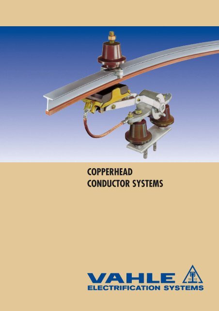
COPPERHEADCONDUCTOR SYSTEMS
19 12VAHLE RAIL SYSTEMSINDEXPageBasic Description, Advantages 2Selection of <strong>Conductor</strong>sand Engineering Data 3Steel <strong>Copperhead</strong> Railsand Accessories 4-6Aluminium <strong>Copperhead</strong> Railsand Accessories 8, 9Hollow Aluminium <strong>Copperhead</strong> Railsand Accessories 10Fibreglass <strong>Copperhead</strong> Railsand Accessories 11PageRailholders and Ground Supports 13Insulators up to 1000 V 14High Voltage Insulators 15Current Collectors 16, 17Spare Parts for Current Collectors 18Installation Information 19Heating <strong>Systems</strong> 20, 21Questionnaire 22Vahle Rails in Action 7, 23Solid Copper Rails and Accessories 12All Vahle Electrification <strong>Systems</strong>back coverBASIC DESCRIPTIONThe <strong>Copperhead</strong> <strong>Conductor</strong> Rail was invented by PAUL VAHLEin the year 1912, and from this beginning the VAHLE COMPA-NY continuously improved and developed the many Rail <strong>Systems</strong>,detailed in this catalogue.The “T” or “hollow T” section and the extruded copperhead isdrawn through a special die, which compresses the copperflanges around the dovetail head of the rail, connecting the twocomponents to a 100 % rigid unit.The well-known VAHLE <strong>Copperhead</strong> <strong>Conductor</strong> Rails representa neat and compact arrangement and have proven an outstandingsuccess for safe power feeding of:Travelling cranes, Loading bridges, Container handlingequipment, Monorails, Hoists, Coking machinery andmany other applications.The VAHLE <strong>Copperhead</strong> <strong>Conductor</strong> Rails are available in sizesto meet individual current requirements from 200 to 1,500 Amps.The main users are:Steel mills, Coking plants, Gas works, Cement industries,Ship yards and Dockside enterprises.Fibreglass-<strong>Copperhead</strong> Rails are preferably used for applicationsin corrosive atmospheres and in locations with highhumidity.Aluminium-<strong>Copperhead</strong> Rails are very economical due to thelight weight of the Aluminium and its high conductivity.Solid-Copper Rails are recommended for heavy duty currentrating and for humid locations.The rails are supplied in 7 m (23’) and 14 m (46’) standardlengths, drilled at either end for joint plates or expansionconnectors. Shorter lengths are available to coincide with yourrun way lengths requirements.We produce a complete range of Accessories, Insulators andCurrent Collectors.SOME ADVANTAGES OF VAHLE RAIL SYSTEMSWith VAHLE-<strong>Systems</strong> you eliminate all drawbacks inherent inthe conventional design of trolley wires, steel angles and steelrails.<strong>Copperhead</strong> Rails ensure an efficient and continuous contact.There is no sparking.The easy maintenance is a proven low factor.No losses due to interruption of service, no downtime.Negligible wear - almost unlimited life of conductors.Much lower resistance between copperhead and carbon pickupshoe.Low weight of rails and saving of steel superstructure andspace.Variation in temperature and resulting expansion and contractionis compensated by standard expansion joints.If required, VAHLE <strong>Copperhead</strong> Rails can also be supplied bentto your specification.Heating systems are available for all VAHLE Rails.For Ducting <strong>Systems</strong> and Housings incorporating VAHLE Railsand Accessories see separate catalogue No. 5 -Heavy Enclosed <strong>Conductor</strong> <strong>Systems</strong>.2
SELECTION OF CONDUCTORS19 12Adequate Ampere Capacity must be providedto carry the anticipated electrical loads:The total Ampere load is determined from the nominal ratedfull load current reduced by the duty cycle ( f ED ) and by adiversity factor for non-simultaneous operation.The average crane motor duty cycle is usually between 40%and 60%, depending on the type of application.A diversity factor of 0.4 to 0.7 can be used when there aremore than one crane on the same runway.Example:3 cranes, each I n = 300 Amps.Length of runway: 100 m (330’)Assumed duty cycle: 60% (ED)Assumed diversity factor: 0.7Ampere load per crane: I n x f ED = 300 A x 0.78 = 234 AAmpere load for 3 cranes: 234 A x 3 = 702 ATotal Ampere load when usinga diversity factor of 0.7: 702 A x 0.7 = 491.4 ASelected conductors: F 35/100or: F 45/50Formula for Voltage Drop Calculation:AC:DC:∆ u = √ 3 x I x l x Z∆ u = 2 l x I x R∆u = Voltage drop [V] R = Resistance [Ohm/m]I = Ampere load [A] l = Length from power feedto end of conductor [m]Z = Impedance [Ohm/m] L = System length [m]duty cycleOther Criterion:a) Select the conductor cross section to carry the calculatedtotal Ampere load and consider the voltage drop calculationto maintain the limits established by the motor manufacturers.The conductor size and/or number of feedpoints should be increased in case the drop is exceedingthe limitations. For very high Ampere loads it may benecessary to provide booster cables.b) Specify the correct VAHLE-conductor by considering thetype of application and environment, such as heavy or lightduty service, corrosion, heat, humidity, internal standards.Effectice Length:l = L power feed located at the end of the systeml = L/2 power feed located at the mid-point of the systeml = L/4 power feed located at both ends of the systeml = L/6 power feed located at L/6 from each end ofthe systemf ED100 % 1.0080 % 0.9060 % 0.7850 % 0.7140 % 0.63Engineering data<strong>Conductor</strong>TypeMaximumContinuousAmps.ResistanceOhm/1000 mImpedance*Ohm/1000 m<strong>Conductor</strong>TypeMaximumContinuousAmps.ResistanceOhm/1000 mImpedance*Ohm/1000 mL 20/ 14 220 0.506 0.573L 20/ 25 256 0.386 0.458L 20/ 50 327 0.251 0.336L 20/100 444 0.148 0.253F 35/ 30 320 0.264 0.345F 35/ 50 410 0.204 0.293F 35/100 529 0.130 0.238F 35/150 632 0.096 0.214F 35/200 724 0.076 0.203F 45/ 50 495 0.178 0.266F 45/100 620 0.119 0.223F 45/150 728 0.089 0.203F 45/200 826 0.072 0.194F 45/300 1000 0.051 0.182F 45/400 1156 0.040 0.174F 45/500 1299 0.033 0.169F 45/600 1432 0.028 0.165A 20/ 14 445 0.183 0.255A 35/ 30 600 0.101 0.227A 35/ 50 675 0.091 0.220A 35/100 795 0.072 0.207A 45/ 50 790 0.071 0.201A 45/100 915 0.060 0.193A 45/150 1025 0.051 0.188A 45/200 1110 0.045 0.184A 45/300 1295 0.036 0.177A 45/400 1451 0.030 0.172AC 45/ 60 1000 0.053 0.187AC 45/110 1080 0.046 0.184AC 45/150 1160 0.042 0.181AC 45/200 1225 0.038 0.179AC 45/300 1370 0.032 0.174K 45/ 60 220 0.300 0.364K 45/110 380 0.164 0.248K 45/150 480 0.120 0.217K 45/200 575 0.090 0.199K 45/300 740 0.060 0.182C 20/200 720 0.088 0.227C 35/400 1080 0.045 0.197C 45/500 1210 0.036 0.187C 45/600 1365 0.031 0.169C 45/800 1580 0.023 0.168Up to 4000 Amp. Special conductor rails are available.* Impedance data based on 150 mm spacing between phases and 50 Hz.Current ratings are based on a temperature rise of 30° C over 30° C ambient.3
19 12STEEL-COPPERHEAD RAILSScale 1 : 1TypeCoppercrosssectionSteelcrosssectionEquival.totalcopperconductorHabWeightMax.continuousCatalog-No.mm 2mm 2mm 2mmmmmmkg/mAL 20/ 14-7 14 150 36 31 6,5 20 1.24 220 100 007L 20/ 25-7 25 150 47 33 8 20 1.34 256 100 017L 20/ 50-7 50 150 72 34 10 20 1.57 327 100 027L 20/100-7 100 150 122 38.5 12 20 2.02 444 100 037Standard lengths:7 m (23´)Best applicable collectors: DVD 1 and DVDMain application:conductor system for hoists and monorails, down-shopand cross travel supply for light cranesTypeCoppercrosssectionSteelcrosssectionEquival.totalcopperconductorHabWeightMax.continuousCatalog-No.mm 2mm 2mm 2mmmmmmkg/mAF 35/ 30-7 30 265 69 32 14.2 35 2.34 320 104 317F 35/ 50-7 50 265 89 33.1 14.6 35 2.52 410 100 047F 35/100-7 100 265 139 36.0 15.3 35 2.97 529 100 057F 35/150-7 150 265 189 38.3 17.3 35 3.42 632 100 067F 35/200-7 200 265 239 40.8 17.3 35 3.87 724 100 077Standard lengths:7 m (23´)Main application:conductor system for heavy monorails, down-shop andcross travel supply for medium duty cranesBest applicable collectors: GSV 1, GSV 2, GSV 4 and GSV 8TypeCoppercrosssectionSteelcrosssectionEquival.totalcopperconductorHabWeightMax.continuousCatalog-No.mm 2mm 2mm 2mmmmmmkg/mAF 45/ 50-7 50 355 102 43.1 14.6 45 3.23 495 100 087F 45/100-7 100 355 152 46.0 15.3 45 3.68 620 100 097F 45/150-7 150 355 202 48.3 17.3 45 4.13 728 100 107F 45/200-7 200 355 252 50.8 17.3 45 4.58 826 100 117F 45/300-7 300 355 352 56.3 17.6 45 5.48 1000 100 127F 45/400-7 400 355 452 59.3 19.6 45 6.38 1156 100 137F 45/500-7 500 355 552 64.3 19.6 45 7.28 1299 100 147F 45/600-7 600 355 652 65.0 23.2 45 8.18 1432 100 157Standard lengths:7 m (23´)Main application:down-shop and cross travel supply for heavy cranes,loading bridges, coking machinery, rapid transit systems etc.Best applicable collectors: GSV 1, GSV 2, GSV 4 and GSV 8The steel sections can be supplied galvanized or with anticorrosion paint.4
ACCESSORIES19 12Scale 1 : 5Expansion JointsTypeMaterialWeightkgCatalog-No.DLM 20/ 14 0.32 100 160DLM 20/ 250.35 100 170brassDLM 20/ 50 0.38 100 180DLM 20/100 0.42 100 190TypeMaterialWeightkgCatalog-No.SMDV 35/ 30 1.15 104 340SMDV 35/ 50 1.15 100 300SMDV 35/100 brass 1.25 100 310SMDV 35/150 1.39 100 320SMDV 35/200 1.48 100 330SMDV 45/ 50 1.46 100 340SMDV 45/100 1.56 100 350SMDV 45/150 1.69 100 360SMDV 45/2001.80 100 370brassSMDV 45/300 3.06 100 380SMDV 45/400 3.29 100 390SMDV 45/500 3.51 100 400SMDV 45/600 3.78 100 410TypeMaterialWeightkgCatalog-No.KBV 45/ 50 3.61 100 420KBV 45/100 3.98 100 430KBV 45/150 4.70 100 440KBV 45/2004.90 100 450brassKBV 45/300 7.59 100 460KBV 45/400 7.76 100 470KBV 45/500 7.94 100 480KBV 45/600 8.01 100 490Rigid JointsTypeMaterialWeightkgCatalog-No.KLM 20/ 14-100 brass 0.35 100 500BLM 20/ 14-100 brass 0.18 100 510MFV 35/ 30-200 brass 0.41 105 893MFV 45/ 50-200 brass 0.46 105 897MFV 45/300-600 brass 1.28 100 5405
19 12ACCESSORIESFeeder ClampsTypeMaterialWeightkgCatalog-No.LM 20/ 14-100 brass 0.17 100 590Cu 20/ 14 0.06 100 600Cu 20/ 25 0.08 104 840copperCu 20/ 500.08 104 850Cu 20/100 0.09 104 860Cu 35/ 30 0.16 104 360Cu 35/ 50 0.17 100 610Cu 35/100 copper 0.18 100 620Cu 35/150 0.19 100 630Cu 35/200 0.20 100 640Cu 45/ 50 0.20 100 650Cu 45/100 0.21 100 660copperCu 45/1500.22 100 670Cu 45/200 0.22 100 680AM 35/ 30-2000.44 105 050brassAM 45/ 50-200 0.60 105 080BK 45/ 50-2001.29 100 700brassBK 45/300-600 1.29 103 460KK 45/300 1.26 100 710KK 45/4001.89 104 760brassKK 45/500 1.89 104 770KK 45/600 1.89 104 780Locating clampsTypeMaterialWeightkgCatalog-No.LK 20 galvanized 0.04 100 550SK 35 galvanized 0.11 100 560SK 45 galvanized 0.12 100 570SKK 45 polyamid 0.23 100 5806
VAHLE RAILS IN ACTION19 12Bridge Crane<strong>Conductor</strong> Transfer EndsCoking Plant7
19 12ALUMINIUM-COPPERHEAD RAILSScale 1 : 1TypeCoppercrosssectionAluminiumcrosssectionEquival.totalcopperconductorHabWeightMax.continuousCatalog-No.mm 2mm 2mm 2mmmmmmkg/mAA 20/14-7 14 150 90 31 6.5 20 0.52 445 103 647Standard lengths:7 m (23´)Best applicable collectors: DVD 1 and DVDMain application:conductor system for hoists and monorails, down-shopand cross travel supply for light cranesTypeCoppercrosssectionAluminiumcrosssectionEquival.totalcopperconductorHabWeightMax.continuousCatalog-No.mm 2mm 2mm 2mmmmmmkg/mAA 35/ 30-7 30 265 160 32 14.2 35 1.00 600 104 327A 35/ 50-7 50 265 180 33.1 14.6 35 1.18 675 103 657A 35/100-7 100 265 230 36 15.3 35 1.63 795 103 667Standard lengths:7 m (23´)Best applicable collectors: GSV 1 and GSV 2Main application:conductor system for heavy monorails, down-shop andcross travel supply for medium duty cranesTypeCoppercrosssectionAluminiumcrosssectionEquival.totalcopperconductorHabWeightMax.continuousCatalog-No.mm 2mm 2mm 2mmmmmmkg/mAA 45/ 50-7 50 355 225 43.1 14.6 45 1.42 790 103 677A 45/100-7 100 355 275 46.0 15.3 45 1.87 915 103 687A 45/150-7 150 355 325 48.3 17.3 45 2.32 1025 103 697A 45/200-7 200 355 375 50.8 17.3 45 2.77 1100 103 587A 45/300-7 300 355 475 56.3 17.6 45 3.67 1295 103 707A 45/400-7 400 355 575 59.3 19.6 45 4.57 1451 103 717Standard lengths:7 m (23´)Main application:down-shop and cross travel supply for heavy cranes,loading bridges, coking machinery, rapid transit systems etc.Best applicable collectors: GSV 1, GSV 2, GSV 4 and GSV 8Locating ClampsTypeMaterialWeightkgCatalog-No.LK 20 galvanized 0.04 100 550SK 35 galvanized 0.11 100 560SK 45 galvanized 0.12 100 570SKK 45 polyamid 0.23 100 5808Extra protection paint for rails is available.Rail supports must be of polyamid or of aluminium for heavy duty & high-temp.
ACCESSORIES19 12Drawings see page 6LA 20/14 = LM 20AMA 35 = AM 35/45KKA 45/ 50–150 = KK 45/300KKA 45/200–400 = KK 45/400–600Scale 1 : 5Feeder ClampsTypeMaterialWeightkgCatalog-No.LA 20/14 brass 0.14 103 540AMA 35/ 30 0.44 105 100AMA 35/ 50 brass 0.44 105 110AMA 35/100 0.44 105 120KKA 45/ 50 1.26 104 790KKA 45/100 1.26 104 800KKA 45/150 brass 1.89 104 810KKA 45/200 1.89 105 130KKA 45/300 1.89 104 820KKA 45/400 1.89 104 830Expansion JointsTypeMaterialWeightkgCatalog-No.DMA 20/14 brass 0.43 103 720SMDA 35/ 30 1.42 104 350SMDA 35/ 50 brass 1.52 103 780SMDA 35/100 1.71 103 790SMDA 45/ 50 1.91 103 800SMDA 45/100 2.79 103 810SMDA 45/150 brass 3.18 103 820SMDA 45/200 6.86 105 679SMDA 45/300 3.81 103 830SMDA 45/400 3.87 103 840KBA 45/ 50 3.86 103 850KBA 45/100 4.00 103 860KBA 45/150 brass 6.94 103 870KBA 45/200 6.86 105 680KBA 45/300 7.93 103 880KBA 45/400 8.01 103 890Rigid JointsTypeMaterialWeightkgCatalog-No.ALM 20/14 brass 0.26 101 020MFVA 35/ 30-100 brass 0.59 105 903MFVA 45/ 50-200 brass 0.66 105 150MFVA 45/300-400 brass 1.28 105 1609
19 12HOLLOW-ALUMINIUM-COPPERHEAD RAILS AND ACCESSORIESScale 1 : 1TypeCoppercrosssectionmm 2Equival.totalcopperconductormm 2HmmammbmmWeightkg/mMax.continuousACatalog-No.AC 45/ 60-7 60 360 41 22 45 2.15 1000 100 777AC 45/110-7 110 410 42 23 45 2.60 1080 100 787AC 45/150-7 150 450 43 24 45 2.96 1160 100 797AC 45/200-7 200 500 43 25 45 3.41 1225 100 807AC 45/300-7 300 600 49 24 45 4.31 1370 100 817Standard lengths: 7 m (23´)Best applicable collectors: GSV 1, GSV 2, GSV 4 and GSV 8Scale 1 : 5TypeMaterialWeightkgCatalog-No.Expansion JointsADV 45/ 60 7.18 104 680ADV 45/110 7.18 104 690ADV 45/150 brass 7.60 104 700ADV 45/200 7.60 104 710ADV 45/300 7.60 104 720Rigid JointsAFV 45/ 601.98 105 601brassAFV 45/110-300 1.90 101 000Locating ClampsSKK 45 polyamid 0.23 100 580Feeder ClampsKA 45/ 602.03 105 649brassKA 45/110-300 1.95 101 01010Extra protection paint for rails is available.Rail supports must be of polyamid or of aluminium for heavy duty & high-temp.
FIBREGLASS-COPPERHEAD RAILS AND ACCESSORIES19 12Scale 1 : 1TypeCoppercrosssectionHabWeightMax.continuousCatalog-No.mm 2mmmmmmkg/mAK 45/ 60-7 60 41 22 45 1.61 220 100 727K 45/110-7 110 42 23 45 2.06 380 100 737K 45/150-7 150 43 24 45 2.41 480 100 747K 45/200-7 200 43 25 45 2.86 575 100 757K 45/300-7 300 49 24 45 3.75 740 100 767Standard lengths:7 m (23´)Main application:down-shop and cross travel supply for medium andheavy duty cranes, loading bridges etc. in locations withvery high humidity and very corrosive atmosphere.Best applicable collectors: GSV 1, GSV 2, GSV 4 and GSV 8Scale 1 : 5TypeMaterialWeightkgCatalog-No.Expansion JointsKDV 45/ 60 5.24 100 860KDV 45/110 5.41 100 870KDV 45/150 brass 5.64 100 880KDV 45/200 5.89 100 890KDV 45/300 6.11 100 900Rigid JointsKFV 45/ 601.98 105 601brassKFV 45/110-300 1.90 101 000Locating ClampsSKK 45 polyamid 0.23 100 580Feeder ClampsKA 45/ 602.03 105 649brassKA 45/110-300 1.95 101 010Rail supports must be of polyamid.11
19 12SOLID-COPPER RAILS AND ACCESSORIESTypeCoppercrosssectionHabWeightMax.continuousCatalog-No.mm 2mmmmmmkg/mAC 20/200-7 200 32 12 20 1.86 720 100 827C 35/400-7 400 45 12 35 3.55 1080 100 837C 45/500-7 500 50 16 45 4.45 1210 100 937C 45/600-7 600 50 25 45 5.32 1365 100 847C 45/800-7 800 50 27 45 7.12 1580 100 857Standard lengths:7 m (23´)Main application:C 20/200 and C 35/400 in conjunction with heavy enclosedconductor systems.C 45/- series for heavy duty current ratings.Best applicable collectors: for C 20/200: DVD, SO and BVSfor C 35/400, C 45/500, C 45/600, C 45/800: GSV 1, GSV 2,GSV 4, GSV 8Scale 1 : 5Expansion JointsTypeMaterialWeightkgCatalog-No.DP 20/200 1.01 100 960DP 35/400 2.56 100 970DP 45/500 brass 7.00 100 940DP 45/600 7.80 100 980DP 45/800 8.50 100 990Rigid JointsTypeMaterialWeightkgCatalog-No.CP 20/200 0.20 101 100CP 35/400 0.50 101 110CP 45/500 copper 1.15 100 950CP 45/600 1.15 101 120CP 45/800 1.33 101 130Locating ClampsTypeMaterialWeightkgCatalog-No.LK 20 steel 0.04 100 550SK 35 steel 0.11 100 560SK 45 steel 0.12 100 570Feeder ClampsTypeMaterialWeightkgCatalog-No.CKK 20/200 copper 0.25 101 140CKK 35/400 copper 1.50 101 150CKK 45/500 copper 1.95 101 500CKK 45/600 brass 1.95 101 160CKK 45/800 brass 1.95 101 17012
RAIL HOLDERS AND GROUND SUPPORTS19 12Scale 1 : 5Rail HoldersTypeMaterialWeightkgCatalog-No.SD 20 steel 0.15 101 180SD 35 steel 0.20 101 190SH 35 steel 0.36 101 200SKD 35 polyamid 0.05 101 220SC 35 steel 0.57 101 230SA 45 aluminium 0.23 104 600SD 45 steel 0.21 101 240SH 45 steel 0.36 101 250SKD 45 polyamid 0.07 101 270SC 45 steel 0.57 101 280SSR 45 steel 0.45 104 730Für A-Schienen nur Schienenhalter Typ SKD oder SA verwenden.Für K-Schienen nur SKD-Schienenhalter verwenden.Scale 1 : 5Rail Supports for GroundTypeMaterialWeightkgCatalog-No.for bolt lengths120 mmCatalog-No.for bolt lengths180 mmSTD 20 steel 0.26 101 290 –STD 35 0.47 105 681 101 300STH 35 steel 0.64 105 682 101 310STC 35 0.94 105 683 101 320 *STD 45 0.49 105 684 101 330STH 45 steel 0.64 105 685 101 340STC 45 0.94 105 686 101 350 *STKD 35 0.33 105 687 103 380STKD 45polyamid0.35 105 688 103 390*Bolt 150 mm13
19 12INSULATORSUP TO 1000 VScale 1 : 5for Leakage- Rail Mechanical Strengths (kp)Catalog-No.Catalog-No.TypeRail Distance MountingMaterial Weight for bolt lengths 30–40 mm for bolt lengths 70 mmbase mm Possibilities Tension Compress. Cantileverkg Phase Ground Phase Groundwhite brownD 80 20 mm 60 800 800 450 0.61 101 380 101 390all white brownVO rails 60 1800 1800 700 porcelain 1.02 105 667 105 668 101 400 101 410VDO 35 35 mm 60 1800 1800 700 1.20 105 669 105 670 101 580 101 590VDO 45 45 mm 60 1800 1800 700 1.22 105 671 105 672 101 660 101 670VAB all 100 2100 2100 770 1.51 105 673 105 674 101 440 101 450VHB rails 100 2100 2100 770 porcelain 1.51 101 520 101 530 112 900 105 572VDB 35 35 mm 100 2100 2100 770 1.49 105 675 105 676 101 620 101 630VDB 45 45 mm 100 2100 2000 770 1.55 105 677 105 678 101 700 101 710light yellowVDK 20 20 mm 60 300 polyamid 0.04 101 780 101 790VDK 35 35 mm 160 600 0.17 101 800 101 810brown yellowGH 45 70 1600 1500 600 0.26 101 820 101 830GH 50 80 1800 2000 900 0.56 101 840 101 850GH 80 all 120 2100 2000 950 0.82 101 860 101 870GHH 30 rails 65 1000 1500 450 resin 0.16 106 090 106 091GHA 75 115 1600 2000 650 0.64 101 900 101 910GHH 75 115 1600 2000 650 0.64 101 880 101 890GHA 80 125 2100 2000 950 0.87 104 650 104 660GHH 80 125 2100 2000 950 0.87 104 630 104 64014
HIGH VOLTAGE INSULATORS19 12Leakage RailMechanical Strengths (kp)Type Voltage Distance MountingMaterialmm Possibilities Tension Compress. Cantilevermax.Temperatur°CWeightkgPhaseCatalog-No.Groundbrown yellowGH 130 6 kV 210 5000 7000 2000 resin 90 1.25 104 670 104 750white brownVAM 6 kV 220 2500 3000 550porcelain 1403.28 101 920 101 930VHM 6 kV 220 2500 3000 5503.28 101 940 101 950brown brownVAK 20 kV 400 2000 2500 500porcelain 1407.09 102 000 102 000VHK 20 kV 400 2000 2500 5007.09 102 020 102 020Scale 1 : 515
19 12HEAVY DUTY CURRENT COLLECTORSScale 1 : 10TypeCapacityAMaterialPick-up ShoesDimensions mmWeightkgCatalog-No.GroundPhase insul. uninsul.GSV 1 100 graphite 50 x 100 x 20 5.20 102 080 102 090 103 920carbonGSV 1/mi 100 met.-impr. 50 x 100 x 20 5.33 102 100 102 110 103 930carbonGSV 1/S 100 graphite 80 x 100 x 30 5.82 102 120 102 130 103 940carbonGSV 1/Smi 100 met.-impr. 80 x 100 x 30 6.01 102 140 102 150 103 950carbonGSV 1/Ms 100 brass 60 x 100 x 12 5.52 102 160 102 170 103 960TypeCapacityAMaterialPick-up ShoesDimensions mmWeightkgCatalog-No.GroundPhase insul. uninsul.GSV 2 200 graphite 80 x 140 x 30 9.30 102 200 102 210 103 980carbonGSV 2/mi 200 met.-impr. 80 x 140 x 30 9.55 102 220 102 230 103 990carbonGSV 2/Nmi 200 met.-impr. 80 x 140 x 30 8.86 102 240 102 250 104 000carbonGSV 2/Ms 200 brass 90 x 125 x 15 9.56 102 260 102 270 104 010GSV 2/GG 200 cast iron 90 x 140 x 15 9.22 102 280 102 290 104 300height of GSV 2/N : 235±55height of GSV 4/N : 250±70CapacityPick-up Shoes WeightCatalog-No.TypeGroundA Material Dimensions mm kg Phase insul. uninsul.GSV 4 400 graphite 100 x 140 x 30 11.72 102 300 102 310 104 020carbonGSV 4/mi 400 met.-impr. 100 x 140 x 30 12.10 102 320 102 330 104 030carbonGSV 4/Nmi 400 met.-impr. 100 x 140 x 30 11.58 102 340 102 350 104 070carbonGSV 4/Smi 400 met.-impr. 140 x 140 x 30 13.16 104 040 104 050 104 060carbonGSV 4/Ms 400 brass 90 x 125 x 15 11.57 102 360 102 370 104 080CapacityPick-up Shoes WeightCatalog-No.TypeGroundA Material Dimensions mm kg Phase insul. uninsul.GSV 8 800 graphite 100 x 140 x 30 15.34 102 380 102 390 104 090carbonGSV 8/mi 800 met.-impr. 100 x 140 x 30 15.79 102 400 102 410 104 100carbonGSV 8/Nmi 800 met.-impr. 100 x 140 x 30 15.43 102 420 102 430 104 140carbonGSV 8/Smi 800 met.-impr. 140 x 140 x 30 18.16 104 110 104 120 104 130carbonGSV 8/Ms 800 brass 90 x 125 x 15 15.05 102 440 102 450 104 150height of GSV 8/N : 270 ±70All malleable iron parts are galvanized. They can be plastic-coated for a smallsurcharge.Insulators are high quality cast resin.16
CURRENT COLLECTORS19 12Scale 1 : 10Type DVD for medium dutyTypeCapacityAMaterialPick-up ShoesDimensions mmWidthmmWeightkgCatalog-No.GroundPhase insul. uninsul.DVD 100 graphite ∆ 60 x 65 105 2.56 102 480 102 490 104170carbonDVDType SO for enclosed <strong>Conductor</strong>s (FK System)TypeCapacityAMaterialPick-up ShoesDimensions mmWidthmmWeightkgCatalog-No.PhaseGroundmetal-SO 120 impr. 105 x 36 x 25 50 1.56 102 540 102 550carbonType BVS for enclosed <strong>Conductor</strong>s (CP System)TypeCapacityAMaterialPick-up ShoesDimensions mmWidthmmWeightkgCatalog-No.PhaseGroundBVS/1 120 metal- 90 x 34 x 42 60 1.40 102 560 –impr.BVS/1 120 carbon 30 x 34 x 42 60 1.30 – 102 570BVS for GroundBVS/2 180 high 90 x 34 x 42 60 1.96 105 891 –dens.BVS/2 180 carbon 30 x 34 x 43 60 1.80 – 105 892Type KSKS for Coking Plants*TypeCapacityAMaterialPick-up ShoesDimensions mmWidthmmWeightkgCatalog-No.PhaseGroundKSKS 2/ 600 17.01 105 170 105 3201 metal-KSKS 2/ 800impr. 30 x 220 x 40 105 17.55 105 180 105 330200 carbonKSKS 2/1000 18.24 105 190 105 340The following KS collector heights “a” will result from thedifferent contact arm dimensions “c”:Dimensions cDimensions amin. normal max.600 340 650 950800 340 750 11501000 340 850 1350**Don’t use on less than 150 sq. mm copperhead rails.KSKS 4/ 600 22.53 102 510 102 5302 metal-KSKS 4/ 800 400 impr. 2 x 30 x 220 x 40 105 23.12 105 590 105 594carbonsKSKS 4/1000 23.85 105 591 105 59517
19 12SPARE PARTS FOR CURRENT COLLECTORSDescriptionPart.No.GSV 1Catalog-No.GSV 1 SCatalog-No.GSV 2Catalog-No.collector spring 1 102 640 102 640 102 800spring bolt 2 102 650 102 650 102 810lever w/thread, mod. 616 3 104 490 104 490 102 660lever w/boring, mod. 615 4 104 500 104 500 102 670insulator w/o bolts phase 102 680 102 680 102 820ground 105 380 105 380 105 492insulator for N-series phase– – 102 830w/o bolts ground – – 105 491spacer tubes, 1 set 6 102 690 102 690 102 840copper shunt lead, 1 set 7 102 710 102 710 102 860carbon brush, graphite 102 720 102 770 102 870carbon brush, metal-impr.102 730 102 780 102 880carbon holder w/clamps 9 102 740 102 790 102 890pick-up shoe, (brass) 10 102 750 – 102 900pick-up shoe, (GG-20) 11 102 760 – 102 910Description58Part.No.GSV 4Catalog-No.GSV 8Catalog-No.collector spring 1 102 920 103 010spring bolt 2 102 930 102 930lever w/thread, mod. 616 3 102 660 102 660lever w/boring, mod. 615 4 102 670 102 670insulator w/o bolts phase 102 820 102 820ground 105 492 105 492insulator for N-series phase 102 830 102 830w/o bolts ground 105 491 105 491spacer tubes, 1 set 6 102 940 103 020copper shunt lead, 1 set 7 102 960 103 040carbon brush, graphite 102 970 102 970carbon brush, metal-impr. 102 980 102 980carbon brush, metal-impr.(140 x 140 x 30) 104 190 104 190carbon holder w/clamps 102 990 102 990carbon holder w/clamps(140 x 140 x 30)9104 200 104 200pick-up shoe (brass) 10 103 000 103 000swing, 1 set 12 – 103 050Description58Part.No.DVDCatalog-No.base plate 1 103 190bow 2 103 200lever 3 103 210lever 5 105 690clip, phase 106 019ground106 020copper shunt lead, 1 set 8 103 250tension spring 9 103 260spacer tube 10 103 270insulator phase 103 150ground105 370triangular carbon, graphite 12 103 280triangular side plate 13 103 1806111067Type GSV.12123281.Type DVD..6...4.3..6.... ... ....12........13131059111189612518
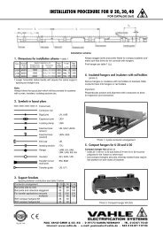
INSTALLATION INFORMATION19 12Expansion diagramFig. A1.Install brackets to I beam or girder, weld or bolt on 2 m (6´ – 6´´)centers for L 20, A 20, C 20 Rails; 2.5 m (8´ – 3´´) centers for allother rails.Spacing between VAHLE Rails is 150 mm std. (6´´), min. 100 mm(4´´) for L 20, A 20, C 20 Rails; 150 mm std. (6´´), min. 120 mm(5´´) for all other Types.For high voltage installations: approx. 250 mm (10´´)Check alignment.2.Secure insulators/rail supports to brackets (in accordance with themounting instructions – see pages 13–15) leaving bolts hand tight.For general Arrangement see Fig. A.When placing the conductors into the insulators, make sure thatthe bayonett clamp (incorporated in most VAHLE insulators) supportsthe rail sliding tight to allow for expansion and contraction.Do not change the position (don’t turn rail holders) when tighteningsupport bolts against steel brackets.Expansion diagramThe chart shows orientation lines for the different conductorrails, considering 42 m expansion joint intervals.For gap setting move the orientation line in parallel up to thepoint presenting the anticipated max. ambient temperature.Then connect point of actual ambient temperature duringinstallation to the right until intersecting with the orientationline. Follow the vertical axis downward to read the air gapdimension in mm.Example:Ambient temperature 25° CAir gap F-Rail = 19 mmAir gap C-Rail = 24 mmAir gap A-Rail = 33 mm3.Connect the VAHLE Rails by rigid- or expansion joints using theholes provided at the ends of the 7 m (23´) sections. For systemsup to 100 m (330´) no expansion joints required. With longer runsuse an expansion joint after every 6 standard lengths of 7 m (23´)intervals. For special heat environment and strong temperaturefluctuations reduce these intervals to 28 m (92´). For gap settingsee adjacent diagram and example.Provide an extra insulator/Rail support close to each expansionjoint – approx. 250 mm.4.Anchor VAHLE Rails for controlled sliding in both directions, byfitting two locating clamps close to the center insulator of the runor in the center between two expansion joints (see Fig. B + C).Fig. BFig. C5.Install feeder clamps at feed points. Bolt to web of rail and braiseto copperhead.Symbols:Rigid JointExpansion JointInsulatorInsulator with Locating Clamps6.Prepare Collector Bracket to suite normal working height and fixingstuds of Current Collectors (See page 16 and 17) and installCollectors securely.19
19 12HEATING SYSTEMS FOR ICING CONDITIONSSelection of heating cable:N [W/m]504540353025220 VH 2,0H 1,44H 0,9H 0,7H 0,48Determine a heating cable of 30 to 45W/m capacity.If no suitable result from adjacent diagrams,devide the length of the systeminto two or more heating sections.Supply lower voltage via a transformerin case of shorter heating sections.N [W/m]20 30 40 50 60 70 80 90 100l [m]5045403530380 V25H 2,0H 1,4420 30 40 50 60 70 80 90 100l [m]Composition of heating cable: <strong>Conductor</strong>: resistor material CrNi, strandedInsulation: TFE-(Teflon-)insulation, natural colour,glass silk sheathSheath: V2A wireH 0,9H 0,7H 0,48Heating [Watt/m] : N ; =U 2capacity R · L 2U = Supply voltage [Volt]R = Resistance of heating cable [Ohm/m]L = Length of heating sections [m]Wire Resistance data:heating cable: H 0.48 R 0.48 Ohm/mheating cable: H 0.70 R 0.70 Ohm/mheating cable: H 0.90 R 1.00 Ohm/mheating cable: H 1.44 R 1.44 Ohm/mheating cable: H 2.00 R 2.00 Ohm/mTolerance: ± 2.5%Outside diameter: ca. 4 mmScheme of heating system formore than one section20
HEATING SYSTEMS FOR ICING CONDITIONS19 12Heating system for steel and aluminium copper head rails:The heating cable is protected by a copper tube.The fixing, easily arranged by galvanized steel clips.Rigid and expansion joints are bridged as above sketches.The ends of heating cable are connected by insulated terminal clamps.Our supply includes:Heating cable of adequate sizeCopper protection tubeFixing clipsGlass fibre hose for expansion jointsInsulated terminal clampsMaterial for end connections(cable lugs etc.)Mounting instructionsAll switches, fuses, cable etc.by others!Heating system for fibre glass and aluminium copper head rails:Scheme for automaticthermostat operationThe heating cable is installed in the hollow web of the VAHLE rails,holes for feed cable drilled at terminal-feed points.Our supply includes:Heating cable of adequate typeFeeder terminalsMaterial for end connnections(cable lugs etc.)Mounting instructionsAll switches, fuses, cable etc. by others.21
19 12QUESTIONNAIRE FOR VAHLE CONDUCTOR SYSTEMSTo our nearest local agency:Adress:Attention of:Date:1. Type of crane/machine to be electrified:2. Voltage: Volts ~/=: Phases: c/s:3. Length of conductor system:4. Number of conductors required: power lines: control lines: neutral (ground):5. Indoor: Outdoor:6. Special site conditions (humidity, dust, chemical influence etc.):7. Temperature conditions: °C min., °C max.8. Type of conductors preferably wanted:9. Number and position of feeder points:10. Mounting position envisaged:(prints and sketches should be submitted whenever obtainable)11. Number of cranes / machines fed from the one system:12. Ampere load of each crane / machine:13. Other pertinent data:For curved tracks, breaks in system etc. please submit prints and sketches.Motor data Questionnaire Ref. 12 (to determine conductor size)Crane 1CurrentHP / kW A % EDCrane 2CurrentHP / kW A % EDCrane 3CurrentHP / kW A % EDMotor Gen. Set.Main HoistingAux. HoistingMain TraverseAux. TraverseMain TravelAux. TravelSlewingLuffing and any other Service22
VAHLE RAILS IN ACTION19 12In accordance with our company’s policy of continued improvement, we reserve the right to amend specifications and details at any time.23
Catalog No. 1a/E 2006MANAGEMENTSYSTEMDQS certified in accordance with DIN EN ISO 9001:2000OHSAS 18001 (Reg. no. 003140 QM OH)Catalog No.<strong>Copperhead</strong> <strong>Conductor</strong> <strong>Systems</strong>1 aBattery Charging <strong>Systems</strong>1 bInsulated <strong>Conductor</strong> <strong>Systems</strong> U 102 aInsulated <strong>Conductor</strong> <strong>Systems</strong> U 20 – U 30 – U 402 bInsulated <strong>Conductor</strong> <strong>Systems</strong> U 15 – U 25 – U 352 cAluminium Enclosed <strong>Conductor</strong> <strong>Systems</strong> LSV – LSVG3 aPowerail Enclosed <strong>Conductor</strong> <strong>Systems</strong> KBSL – KSL – KSLT 4 aPowerail Enclosed <strong>Conductor</strong> <strong>Systems</strong> VKS – VKL4 bPowerail Enclosed <strong>Conductor</strong> <strong>Systems</strong> MKLD – MKLF – MKLS 4 cPowerail Enclosed <strong>Conductor</strong> System VKS 104 dPowerail Enclosed <strong>Conductor</strong> System KBH4 eHeavy Enclosed <strong>Conductor</strong> <strong>Systems</strong> 5Trolley Wire and Accessories 6Cable Tenders 7Cable Carriers for -tracks 8 aCable Carriers for Flatform Cable on -beams8 bFCable Carriers for Round Cable on -beams8 bRCable Carriers for -tracks 8 c<strong>Conductor</strong> Cables and Fittings8 LSpring Operated Cable Reels9 aVAHLE POWERCOM ® – Data Transmission <strong>Systems</strong>9 cCPS ® – Contactless Power Supply9 dSMG – Slotted Microwave Guide9 eWCS – Position Encoding System9 fMotor Powered Cable Reels 100108 · Printed in Germany · 2006-0978 · 1400 · 4/06PAUL VAHLE GMBH & CO. KG • WESTICKER STRASSE 52 • D 59174 KAMEN/GERMANY • TEL. (+49) 23 07/70 40Internet: www.vahle.de • e-mail: info@vahle.de • FAX (+49) 23 07/70 44 44