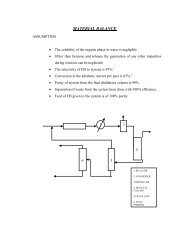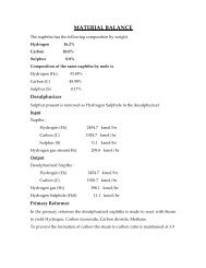
DESIGN OF EQUIPMENTS ABSORBER PROCESS DESIGN OF ...
DESIGN OF EQUIPMENTS ABSORBER PROCESS DESIGN OF ...
DESIGN OF EQUIPMENTS ABSORBER PROCESS DESIGN OF ...

Create successful ePaper yourself
Turn your PDF publications into a flip-book with our unique Google optimized e-Paper software.
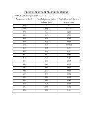
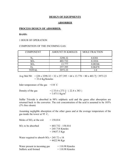
<strong>PROCESS</strong> <strong>DESIGN</strong> <strong>OF</strong> <strong>ABSORBER</strong>:BASIS:1 HOUR <strong>OF</strong> OPERATION<strong>DESIGN</strong> <strong>OF</strong> <strong>EQUIPMENTS</strong><strong>ABSORBER</strong>COMPOSITION <strong>OF</strong> THE INCOMING GAS:COMPONENT AMOUNT IN KMOLES MOLE FRACTIONN 2 3298.32 0.8301SO 3 403.732 0.1016SO 2 13.777 0.00346O 2 257.395 0.06478TOTAL 3973.23 1.0Avg Mol Wt = [28 x 3298.32 + 32 x 257.395 + 64 x 13.778 + 80 x 403.7] / 3973.23= 33.6 Kg/KmolesInlet temperature of the gas=110 Û CDensity of the gas = [ 33.6 x 273 ] / { 22.4 x 383 }= 1.0711 Kg/m 3Sulfur Trioxide is absorbed in 98% sulphuric acid and the gases after absorption arereturned back to the converter. The exit concentration of the acid is assumed to be 103%(3% free oleum)Assuming negligible absorption of the other gases and at the average temperature of thegas inside the tower at 95 Û C,Moles of SO 3 at the exit = 158.014SO 3 to be absorbed = 403.732 - 158.014= 245.718 Kmoles= 19657.5 KgsWater required to absorb SO 3 = 245.72 x 18= 4422.96 KgsWater present in incoming gasSulfuric acid formed= 110.98 Kmoles= 110.98 Kmoles
= 10876.04 KgsFree SO 3 with it = 326.3Total SO 3 absorbed by water = 110.98 x 80 + 326.3= 9204.7 KgsSO 3 to be absorbed in 98% acid = 19657.5 – 9204.7= 10452.8 KgsLet ‘W’ be the weight of 98% acid used in the tower,Then,SO 3 absorbed by it = [W x 0.02 x 80] / 18Total weight of 100% acid = W + { [W x 0.02 x 80] / 18 }= 1.0889 WFree SO 3 associated with itTotal WeightKgs of SO 3 absorbed by W KgsNow,For 0.12157 Wthen, For W= 0.03 x 1.0889 W= 0.03267 W= (1.0889 + 0.03267) W= 1.12157 W= 1.12157 W – W= 0.12157 W= 10452.8 Kgs= 85982 Kgs acid / Hr= 23.88 Kgs/sThus, Liquid flow rate is given as,L= 23.88 Kgs/s'HQVLW\ !L) = 1850 Kg/m 3Gas Flow Rate = [3973.23 x 33.6] / 3600= 37.08 Kgs/sG= 37.08 Kgs/s'HQVLW\ !G) = 1.0711 Kg/m 3DIAMETER CALCULATION:Adopting the methodology as given in RICHARDSON AND COULSON,VOLUME 6,First we calculate,>/*@ [^!G !L) } 0.5= 0.0155In the Literature given by RICHARDSON & COULSON, Pg 544
From the Plot of K 4 9V >/*@ [^!G !L) } 0.5K 4 at flooding line = 6.1Lets choose the following packing, as given in RICHARDSON & COULSON, Pg 533Material= 3” Ceramic, Raschig RingsNominal Size = 76 mmBulk Density = 561 Kg/m 3Surface Area = 69 m 2 /m 3Packing Factor = 65 m -1Voidage = 75%Then,G * = [ {K 4 [ !G !L – !G )} / {13.1 x F p [!L L) -0.1 }] 0.5= [ {6.1 x 1.0711 ( 1850 - 1.0711 )} / {13.1 x 65 x (6 x 10 -3 / 1850) 0.1 }] 0. 5= 7.08 Kg/m 2 -sDesigning for a Pressure Drop of 42 mm water per m of packing, we haveThen,And,K 4 = 1.9% Loading = {1.9 / 6.1} 0.5 x 100%= 56 %G * = 3.95 Kg/m 2 -sThen, Cross Section Area Required,A = [Mass Flow Rate] / G *= 37.08 / 3.95= 9.38 m 2Thus,D i = [{4 x 9.38 }/Œ@ 0.5= 3.45 mHence the Diameter which is calculated from this approach is 3.45 mHEIGHT <strong>OF</strong> PACKING CALCULATION:L= 23.88 Kgs/s'HQVLW\ !L) = 1850 Kg/m 3G V = 37.08 Kgs/s'HQVLW\ !G) = 1.0711 Kgs/m 3Volumetric Flow rate of the entering gas is given by,G v = [37.08 / 1.0711]= 34.62 m 3 /s
Gas Velocity at the bottom of the tower is given by,V bg = 34.62 / 9.38= 3.69 m/sMass Flow Rate at the top of the tower is given by,G T = [ 3727.51 x 33.6 ] / 3600= 34.79 Kgs/sVolumetric Flow rate at the top of the tower is given by,G t = [34.79 / 1.0711]= 32.48 m 3 /sGas Velocity at the top of the tower is given by,V bg = 32.48 / 9.38= 3.46 m/sThen Average Gas Velocity is given as,V avg= 3.57 m/sAnd, Average Gas Velocity in the Packing,V P = 3.57 / 0.75= 4.76 m/sLiquid Flow = 23.88 / 9.38= 2.54 Kgs/m 2 -sGiven that,Surface Area of Packing = 69 m 2 /m 3Liquid Density = 1850 Kg/m 3Then,Wetting Rate = 2.54 / [1850 x 69]= 1.9898 x 10 -5 m 3 /m-sThe Above wetting rate is greater than the required minimum limit and this is adequatefor wetting the packing.The Methodology adopted for the calculation of Height of the Packing is referred fromthe literature by NORMAN W.S (ABSORPTION, DISTILLATION AND COOLINGTOWERS), Pg 214.The Average Properties of the gas at the temperature are given as follows,'HQVLW\ RI WKH JDV PL[WXUH !G) = 1.0711 Kg/m 39LVFRVLW\ RI WKH JDV PL[WXUH mix) = 2.772 x 10 -5
Diffusivity of the gas (D) = 8.2 x 10 -6 m 2 /sSchimidt Number (N Sc )mix >!G) x (D)]= 2.772 x 10 -5 / [1.0711 x 8.2 x 10 -6 ]= 3.15As given in the literature,The Reynolds number is calculated for the Standard Wetted Wall Column having thediameter,d= 0.083 ft= 0.0253 mReynolds Number (N Re )>!G x d x V P @mix)= [1.0711 x 4.76 x 0.0253] / (2.772 x10 -5 )= 4654Cited in the Reference NORMAN W.S (ABSORPTION, DISTILLATION ANDCOOLING TOWERS), Pg 212, the co-relation is,k G x (RT/ V P ) x (P/p BM [^mix >!G x D]} 0.5 = [ ^>!G x d x V P @mix)} -0.25Now,With (P/p BM ) =1(approx), we have,k G = [ 0.04 x (4654) -0.25 x (3.15) -0. 5 x 15.61 x 3600 ] / {1.318 x 368}= 0.316 lb mole / hr-ft 2 -atmAlso given in the table of NORMAN W.S (ABSORPTION, DISTILLATION ANDCOOLING TOWERS), Pg 210 & Pg 211For the conditions specified above the partial pressure of SO 3 in equilibrium with the acidis extremely small and it may be assumed that the absorption is controlled by gas film.Partial Pressure of SO 3 in the gas at inlet,p 1 = 0.1016Partial Presure at the Outlet, p 2 = [0.1016 x 0.0423]/[0.8984+0.1016x 0.0423]= 4.76 x 10 -3Mean Driving Force = [¨ S 1 - ¨ S 1 ] / ln [¨ S 1 / ¨ S 1 ]= 0.0316 atmSO 3 absorbed= 19657.5 / ( 80 x 0.454) lbmoles= 541.71 lbmoles/ hrArea of Packing = 541.71 / (0.31 x 0.0316)= 55300 ft 2= 5140 m 2Area of Packing/ft height = 69 x 9.38
= 647.22Height of Packing Required = 5140 / 647.22= 7.94 mTherefore the height of the packing required is 8m
MECHANICAL <strong>DESIGN</strong> <strong>OF</strong> <strong>ABSORBER</strong>Inner Diameter of vessel, D i = 3.45 mHeight of the packing required = 8mSkirt height= 2mDensity of material column = 7700 Kg/m 3Wind pressure = 130 Kg/m 2MATERIAL :Carbon SteelPermissible tensile stress ( f )= 950kg/cm 2THICKNESS <strong>OF</strong> SHELL:Thickness of shell, t s= [p D / (2f J – p)] + cWhere,Inner Diameter of vessel, D i = 3.45 mWorking Pressure = 1.013 x10 5 N/m 2Design Pressure, p = 1.05 x 1.013 x10 5 N/m 2= 0.10635 N/mm 2Permissible Stress = 95 N/mm 2Joint Efficiency(J) = 0.85Corrosion allowance = 3mmHence,t s =2.25 mmWe take thickness as 8mmSo outer diameter of shell Do = 3.45 m + 2 x 0.008m = 3.466 mSTRESS ANALYSIS AND SHELL THICKNESS AT DIFFERENT HEIGHTS:Let X be the distance in “m” from the top of the shell, then1. AXIAL STRESS DUE TO PRESSUREAxial stress due to pressure, f ap = p D i / 4 ( ts – c )= 184 Kg/cm 22. STRESS DUE TO DEAD LOADa) Compressive Stress due to weight of shell up to a distance XOuter Diameter Of shell= D i + 2 t s
= 3.466 mDensity of Shell material, ρ s = 7700 Kg /m 32f ds = π/4 ( D o – D 2 i )ρ s X] / π /4 ( D 2 o – D 2 i )= 0.77 X Kg/cm 2b) Compressive stress due to weight of insulation at height XLet,And,Material for Insulation = AsbestosThickness of insulation, t ins = 100 mmDensity of insulation = 575 Kg/m 3D insD m= Diameter of insulation,= Mean diameter of vesselFor large diameter column,D ins = D mf dins = [π D ins t ins ρ ins X] / {π D m ( t s – c )}= 1.15 X Kg /cm 2c) Compressive stress due to liquid in column up to height XDensity of liquid, ρ l = 1850 Kg/m 3f dliq = [ ( π /4 ) D i 2 X ρ l ]/ π D m ( t s – c )= 3.19 x10 6 N/m 2= 31.9 Kg/cm 2d) Compressive stress due to attachmentWe have the following attachments in the absorber columnPiping weightHead weightLadderHead weight (approximately) = 2500 KgsWeight of Ladder = 160 X KgsTotal compressive stress due to attachments f d is given by,f d(attachments) = (Piping Weight + Head Weight + Ladder)/[π D i ( t s – c )]= (2500 + 160X) / (π x 0.5 x 345)= 4.613 + 0.295 X Kg/cm 2e) Stress due to Wind
To determine the value of Xf w = [ 1.4 x 130 x X 2 [@>Œ [ 3450 x 5 ]= 0.3358 X 2 Kg/cm 2Permissible Stress = 95 N/mm 2And,f tmax = f wx + f ap – f dxOr, 0.3358 X 2 – (36.513 + 2.215X ) + 184 – 950 x 0.85 = 0Solving the above equation,We get,X = 47.752 mOr, 0.3358 X 2 – 2.215 X - 660.01 = 0SUPPORT FOR <strong>ABSORBER</strong>Skirt support is used to support the absorber column.Material to be used = Structural steel ( IS 800)Inner Diameter of the vessel, D i = 3.45 mOuter Diameter of the vessel, D o = 3.466 mHeight of the Packing,= 8 mDensity of carbon steel, ρ s = 7700 kg /m 3Total weightDiameter of SkirtConsidering the height of Skirt is 8mWind Pressure is 1285 N/m 2Stress due to Dead WeightThickness of the skirt support is t skStress due to dead loadf d = Total Weight /π D s t sk= 9.302 x 10 5 N/m2= Weight of vessel + Weight of Attachments= (π/4) ( D 2 o – D 2 i ) x H x ρ s x 9.81 +(π /4) D 2 i x H x ρ l x 0.6 +(π /4) D 2 i x H x ρ p + 35000N + 1600 x H= 1.422 x10 7 N= 3.45 mDue to wind loadThe forces due to wind load acting on the lower and upper parts of the vessels aredetermined as
p lw = k p 1 h 1 D op uw = k p 2 h 2 D oWhere K is coefficient depending on the shape factor.k=0.7 for cylindrical surfacep 1 is wind pressure for the lower part of the vessel.p 2 is wind pressure for the upper part of the vesselp 1 = 700 N /m2p 2 = 2000 N /m2h 1 =20mh 2 =14 mp lw = k p 1 h 1 D o= 47686.8p uw = k p 2 h 2 D o= 149872.8Bending moment due to wind at the base of the vessel is determined byM w =p lw (h 1 /2) + p uw ( h 1 + h 2 /2)=4.09 x 10 6 Nmf wb = 4 x M w / πD o t sk=10.71 x10 7 /t skStress due to Seismic LoadLoad F= CWW is total Weight of vesselC is Seismic CoefficientC=0.08f sb = ( 2/3)[ CWH/π R ok 2 t sk ]Where,R ok is radius of skirt= 4.159 x 10 6 /t sk N/m2Maximum Stress at bottom of Skirtf tmax = ( f wb or f sb ) – f db= (3.229 x 10 6 / t sk ) N / m 2Permissible tensile Stress for structural steel = 140 N/mm 2t sk = 0.023mHence thickness of skirt is 23 mmMaximum Compressive Stressf cmax = ( f wb or f sb ) + f db= (5.089 x 10 6 / t sk ) N /m 2Yield point = 200 N / mm 2f c permissible
Maximum Compressive Stress between bearing plate and foundationf c = Total Weight /A + M w /2D sko = 5 .018mD ski = 4.866mA = ( π/4) ( D sko 2 – D ski 2)f c = 6.911 x 10 6 N / m 2F = (3 x f c x L 2 ) / t b2Permissible stress F in bending is 157.5 N/mm 2t b = 118 mmAnchor Bolt,W min =7.86 x 10 5 N (assumed)F c = (W min / A ) – (M w /Z)= - 9.9 x 10 5 N /m2F c is ‘- ve’ , vessel skirt must be anchored to the concrete foundation by anchor boltNumber of bolt = 4.866 x 10 3 / 600= 32P bolt = (f c ) min x A) / N= 3.11 x 10 5 N
HEAT EXCHANGER<strong>PROCESS</strong> <strong>DESIGN</strong> <strong>OF</strong> HEAT EXCHANGER:BASIS:1 HOUR <strong>OF</strong> OPERATIONGIVEN:THE FLUIDS ARE:WATER:INLET TEMPERATURE = 25 Û COUTLET TEMPERATURE = 40 Û CSULFURIC ACID:INLET TEMPERATURE = 112 Û COUTLET TEMPERATURE = 30 Û CThe Sulfuric acid coming out from the absorption towers are cooled from a hightemperature to a lower temperature in a Shell and Tube Type Heat Exchanger. Waterwhich enters the Heat Exchanger at room temperature is heated to 40 Û C and comes out ofthe system.BULK TEMPERATURE <strong>OF</strong> THE ACID = (30 + 112)/2= 71.0 Û CPROPERTIES <strong>OF</strong> WATER AT BULK TEMPERATURE OBTAINED FROM THELITERATURE ARE AS FOLLOWS:PROPERTIESNUMERICAL VALUE1. BULK TEMPERATURE <strong>OF</strong> WATER 32.5 Û C '(16,7< !w 994.86 Kg/m 33 SPECIFIC HEAT CAPACITY, C Pw 4.184 KJ/Kg-K4. THERMAL CONDUCTIVITY, K w 0.623 W/m-K 9,6&26,7< w 0.8 Centipoise
PROPERTIES <strong>OF</strong> SULFURIC ACID AT BULK TEMPERATURE OBTAINEDFROM THE LITERATURE ARE AS FOLLOWS:PROPERTIESNUMERICAL VALUE1. BULK TEMPERATURE <strong>OF</strong> WATER 71 Û C '(16,7< !h 1850 Kg/m 33 SPECIFIC HEAT CAPACITY, C Ph 1.4435 KJ/Kg-K4. THERMAL CONDUCTIVITY, K h 0.655 W/m-K 9,6&26,7< h 6.83 Centipoise1. HEAT LOAD:HEAT INPUT = HEAT OUTPUTm h = 48572 Kg/Hr= 13.49 Kg/sQ = m h x C Ph [>û7@ h= 13.49 x 1.4435 x 10 3 x (112 - 30)= 1.596 x 10 6 J/sQ = 1596.7 x 10 3 J/sOverall Heat Balance gives,m w x 4187 x 15 = 1596.7 x 10 3m w = 25.42 Kg/s2. LMTD:ACID WATER û7TEMPERATURES 112.0 40 72 Û CTEMPERATURES 30.0 25 5 Û CLMTD = [(112-40)-(30-25)] / ln [(112-40)-(30-25)] = 25.11 Û CR = [112-30] / {40-25} = 5.46S = [40-25] / {112-25} = 0.172From the graph of F T against S at various R, we haveF T = 0.834Then, LMTD = 20.94 Û C
3. ROUTING:Shell SideTube Side= Sulfuric Acid= Cooling Water4. DETERMINATION <strong>OF</strong> AREA:Assume U o = 630 W/m 2 -KThen, Area can be calculated as,A = 1596.7 x 10 3 / [630 x 20.94]= 121.03 m 25. CHOICE <strong>OF</strong> TUBES:From the tubing characteristics as given in PERRY,We choose the following dimensions of the tube,1 inch Outer Diameter tubes with 1.25 inch Triangular Pitch,16BWGD oD iPï= 1.0 inch= 25.4 mm= 0.87 inch= 22.1 mm= 31.75 mmLet us assume the tube to be of length of 6m.Number of tubes Œ [ [ = 2536. CORRECTION <strong>OF</strong> HEAT TRANSFER AREA:From the tube count table,We have For TEMA P or S (1- 4 Exchanger)1 Shell Pass and 4 Tube PassesDiameter of Shell, D s = 635 mmNumber of Tubes, N t = 250Corrected HT AreaŒ [ [ [ = 119.69 m 2Corrected U oc = 637.07 W/m 2 -K7. CALCULATION <strong>OF</strong> INSIDE HEAT TRANSFER COEFFICIENTArea of the tubes, a t >Œ [G i 2 x N t ] / [ 4 x N P ]
= 0.024 m 2Mass velocity G st = 25.42 / 0.024= 1059.16 Kg/m 2 -sVelocity inside the tubes, V t P>! [D t ]= 1059.16 / 994.865= 1.06 m/sThe above velocity is also within acceptable limits of 1 to 3 m/s.Reynolds Number, N Re= [G st x d i @ = [1059.16 x 22.1 x 10 -3 ] / 0.8 x 10 -3= 29260Prandtl Number, N Pr = 5.37(h i d i / k) = j H x (N Re ) x (N Pr ) (1/3)where,j H = 0.0036Then,(h i d i / k) = 184.45h i = 5199 W/m 2 K8. CALCULATION <strong>OF</strong> OUTSIDE HEAT TRANSFER COEFFICIENTLength of tube L = 6 mBaffle Spacing,L s = 0.266 x Ds= 168.9 mmNumber of baffles, N b +1 = 6 / L sN b = 35S mv s= [ L s (P ï - D o ) D s ] / P ï= [(0.03175 – 0.0254) x 0.1689 x 0.635 / 0.03175= 0.02145 m 2= m h / (S m [ !h)= {48572/3600} / (0.02145 x 1850)= 0.340 m/sThe above value of velocity is also in the range of 0.3 to 1m/s, so this is alsoacceptable.
Equivalent Diameter, d e = 1.1 {31.75 2 – 0.917 x 25.4 2 }/ 25.4= 18.04 mmN Re= [d e *@= [ 629 x 18.04 x 10 -3 ] / 6.83 x 10 -3= 1661N Pr = 42.9From the graph, we havej H = 0.019(h o d e / k) = j H (N Re ) (N Pr ) (1/3) w) 0.14= 103.65h o= 3763 W/m 2 K[ 1 / U o ] = [ 1 / h o ] + [ D o / D i ] [ 1 / h i ] + [D o x ln {D o /D i } / (2K w )]+ [ 1 / h od ] + [ D o / D i ] [ 1 / h id ]Taking,[ 1 / h od ] = 1 / 3000 (m 2 -K)/W[ 1 / h id ] = 1 / 5000 (m 2 -K)/W[ 1 / U o ] = 1.083 x 10 -3 (m 2 -K)/WU o= 923 W/(m 2 -K)Note: As this value of U o is greater than the corrected value of U oc , so the designwith the above specifications is accepted.9. PRESSURE DROP CALCULATION:For Tube side,f = 0.079 x (N Re ) -0.25= 0.00604û3 L = [(4fLV t2 [!f ] / {2 x D i }= 3666 N/m 2û3 t [>!f x V t2/ 2]= 1397 N/m 2
û3 T = N p û3 L û3 t )= 20252 N/m 2= 20.25 KPaNote: As the value of the pressure drop is less than 70KPa, the design isacceptable from the tube side pressure drop consideration.For Shell Side,Pressure Drop in the Cross Flow section is calculated by,û3 c = [{b x f K x W 2 x N c `!f x S m2 @[^w b} 0.14 KN/m 2N Re = 1668b = 2 x 10 -3f K = 0.25!h !f) = 1850 Kg/m 3m h (W) = 13.49 Kg/sN c = [ D s ( 1 – 2 {L c /D s } ) / P p ]= 635 x (1-2 x 0.25) / 22= 14.43= 14.5û3 c = [{2 x 10 -3 x 0.25 x 13.49 2 x 15}/( 1850 x 0.02145 2 )] KN/m 2= 1.55 KPaPressure Drop in End Zones is calculated as,û3 e û3 c ( 1 + {N cw / N c } ) KN/m 2N cw= 0.8 l c / P p= [0.8 x 0.25 x 635] / 22= 6û3 e = 1.55 [1 + ( 6 / 14.5 )]= 2.191 KPaPressure Drop in Window Zonesû3 w = [ b x W 2 x ( 2 + 0.6 N cw ) / { S m x S w [ !f }] KN/m 2b = 5 x 10 -4S w = S wg - S wt
From the graph from PERRY Fig. 10-18, Pg. 10-29S wg = 100 inch 2= 0.0645 m 2S wt = ( N t / 8 ) x ( 1 – F c [Œ [' o2From the graph from PERRY Fig. 10-16, Pg. 10-28F c = 0.65S wt = (250 / 8) x ( 1 – 0.6 [ Œ [ 2= 0.0222 m 2S w= S wg - S wt= 0.0645 – 0.0222= 0.0423 m 2û3 w = [ 5 x 10 -4 x 13.49 2 x ( 2 + 0.6 x 6 ) / {0.02145 x 0.0423 x 1850}]= 0.303 KPaTherefore the total Pressure Drop on the shell side is calculated by the followingrelationû3 s (TOTAL)[û3 e + (N b – [ û3 c + N b [ û3 w= 2 x 2.191 + 35 x 1.55 + 36 x 0.303= 69 KPaAs this value of Pressure Drop on the shell side is less than the 70 KPa, the designis acceptable from the Pressure Drop Point of View.Thus, the design is acceptable from process design consideration.SUMMARY <strong>OF</strong> <strong>PROCESS</strong> <strong>DESIGN</strong> FOR HEAT EXCHANGERMass flow rate of acid = 13.49 Kg/sMass flow rate of water = 25.42 Kg/sShell outer diameter = 635 mmNumber of tubes = 250Tube OD= 1 inchPitch (Triangular) = 1.25 inchTube length= 6 mShell side pressure drop = 69 KPaTube side pressure drop = 20 KPaHeat Exchanger type = TEMA P or S type 1-4 Heat Exchanger
MECHANICAL <strong>DESIGN</strong> <strong>OF</strong> HEAT EXCHANGERWorking Pressure = 1 atmInlet Temperature = 110 Û CDesign pressure= 1.1 atmNumber of tubes = 250Shell diameter= 635 mmThe entire mechanical design is referred from the literature in <strong>PROCESS</strong> EQUIPMENT<strong>DESIGN</strong> by M.V JOSHI.1. SHELL THICKNESSMaterial: IS 2825-1969 Grade I plain Carbon steel.Shell thickness , (t S ) = [{P x D i }/ ( 2fJ – P )]= [{635 x 1.1} / (2 x 95 x 0.85 – 1.1)]= 4.29 cm= 5 mmFrom the Table 9.2, its found that minimum shell thickness when severeconditions are not expected is 8mm, which includes the Corrosion Allowance.2. NOZZLESTake inlet and outlet nozzles as 100mm diameter.Vent nozzle = 25mm diameterDrain nozzle = 25mm diameterRelief Valve = 50 mm diameter.Nozzle thickness = [ P x D i ] / { 2 f J - P }= 0.68 mmMinimum nozzle thickness is 6mm and 8mm is choosen which includes thecorrosion allowance.Also only the inlet and outlet nozzles need compensation. The compensationrequired is minimum and is given by pads of 10mm thickness.3. HEADTorispherical heads are taken for both ends.R c (Crown radius)= 635 mm
R nk (knuckle radius) = 63.5 mmHead thickness ( t h ) = [ P x R c x W ] / { 2 f J }Where,W = (1/4) x [ 3 + (R c / R nk ) 0.5 ]= 1.54Head thickness ( t h ) = [ P x R c x W ] / { 2 f J }Head thickness= 6.66 mmTherefore we take Head Thickness as that of the Shell Thickness = 8mm4. TRANSVERSE BAFFLESNumber of Baffles = 35Baffle cut = 25%Baffle thickness = 6mm (standard)5. TIE RODS AND SPACERSDiameter of tie rods = 10mmDiameter of Spacers = 8mm6. FLANGE <strong>DESIGN</strong>Flange is ring type with plain face.Flange material: IS 2004-1962 Class 2 Carbon SteelBolting steel: 5% Chromium, Molybdenum SteelGasket Material: AsbestosShell ODShell ThicknessShell ID= 0.635 m= 0.008 m (g)= 0.627 mAllowable stress for flange material = 100 N/mm 2Allowable stress of bolting material = 138 N/mm 26 (i). DETERMINATION <strong>OF</strong> GASKET WIDTHMinimum design yield seating stress , y = 52.386 N/mm 2Gasket factor, m = 3.75Gasket Size:Outer Diameter = 680 mm
Inner Diameter = 650 mmMean Gasket Diameter, G = 665 mmMinimum gasket width,Choose N = 30 mm.Basic gasket seating width, b o = 30/2= 15 mmEffective Gasket Seating Width, b = 2.5 x [b o ] 0.5= 9.7 mm6 (ii). ESTIMATION <strong>OF</strong> BOLT LOADSUnder atmospheric conditions, the bolt load due to gasket reaction is given byW m1 = π b G y= π x 2 x 665 x 52.39= 1061 KNLoad due to design pressureW m2 = H+H TW m2 = πG 2 P/4 + πG(2b)mp= 549.23 KNW m1 > W m2 Hence, the controlling load is W m16 (iii). CALCULATION <strong>OF</strong> MINIMUM BOLTING AREA:A m = A o= W / SS = allowable stress for bolting materialA m1 = A o = 1061 x 10 3 /138 = 7688.4 mm 26 (iv). CALCULATION <strong>OF</strong> OPTIMUM BOLT SIZE.Bolts are of 5% Cr Mo SteelNumber of bolts = G / [b o x 2.5]= 665 / [15 x 2.5]= 18 boltsDiameter of bolts = [(A m1 / Number of bolts ) x ( 4 / π) ] 1/2= 24 mm7. FLANGE THICKNESSThickness of flange , t f= [G√(p/Kf) ] + C
Where,C is the Corrosion allowanceh G is radial distance from gasket load reaction to bolt circleHydrostatic end force, H = (π /4) G 2 p= 38.69 KNK =1/[ 0.3 + {( 1.5 W m h G ) / (H x G)}]h G = (B – G )/2Where,B = Outside diameter of Gasket + 2xDiameter of Bolt +12mm= 680 + 2 x 24 + 12= 740 mmThen, h G = (B – G )/2= 37.5 mmK= 1/[ 0.3 + {( 1.5 W m1 h G ) / (H x G)}]= 0.382t f = [G√(p/Kf) ] + C= 35.8 + C= 38 mmHence the thickness of flange = 38 mmTUBE SIDEMaterial:Stainless steel ( IS- grade 10)Thickness of tube = t f = {P x D o } / ( 2 f J + P)Where,Working pressure = 12 N/mm 2Design pressure, P = 14 N/mm 2Permissible Stress, f = 100.6 N/mm 2Joint Efficiency, J = 1Thickness of tube = 1.65 mmUse tube with thickness of 2mmNo Corrosion allowance, since the tubes are of stainless steel.1. TUBE SHEETThe tube sheet is held between shell flange and the channel. The joint on the shellflange side is of male and female facing and on the channel side of ring facing,since the pressure on the channelThickness of Tube Sheet , t ts= FG√[(0.25 P)/f]
Where,F = 1.25Thickness of tube sheet = 155 mm2. CHANNEL AND CHANNEL COVERMaterial :Carbon SteelPermissible stress,f = 95 N/mm 2For Ring type gasketK =0.3Thickness of channel, t h =G √ [(K x P) /f ]=140 mm4. GASKET SIZEWidth of ring gasket, N= 30 mmGasket material: Steel Jacketed AsbestosGasket factor, m = 5.5Minimum design seating stress, Y a = 126.6 N / mm 2Basic gasket seating width, b o = N / 8= 30 / 8= 3.75 mmEffective gasket seating width,bMean diameter, G= b o= 665 mmDesign pressure, P = 14 N/mm 2Under atmospheric conditions, the bolt load due to gasket reaction is given byW m1= π b G Y a= 991.8 KNAfter the internal pressure is applied, the gasket which is compressed earlier, isreleased to some extent and the bolt load is given byW m2= π x 2 b x G x m x P + ( π / 4 )G 2 P= 6069 KN“f ” is permissible tensile stress in bolts under atmospheric condition
Bolt Material: 5%Cr Mo Steel,f = 140.6 N/mm 2A mA m1A m2= area of bolt= W m1 / f a= 7075 mm 2= W m2 / f b= 43165 mm 2Number of bolts = (mean diameter) / 10 x 2.5= 26 boltsTo determine the size of bolts , the larger of above two areas should be consideredDiameter of bolts,D b = [( A m2 / Number of bolts ) x ( 4 / π )] 1/2= 46 mm5. THICKNESS <strong>OF</strong> NOZZLEConsidering inlet and outlet diameter to be 100mm, then thickness of the nozzle isgiven by,Thickness of nozzle, t n = (P x D n ) / [2 x f J – P]Permissible stress, f = 95 N/ mm 2Joint Efficiency, J = 0.85Then,Thickness of nozzles =10 mm6. FLANGE THICKNESS:Flange material: IS 2004-1962 Class 2 Carbon SteelThickness of the Flange , t f = [G√(P/Kf) ] + CWhere,C is the Corrosion allowanceAllowable stress for flange material, f = 100 N/mm 2h G is radial distance from gasket load reaction to bolt circleHydrostatic end force, H = (π /4) G 2 P= 4863 KNK =1/[ 0.3 + {( 1.5 W m h G ) / (H x G)}]h G = (B – G )/2Where,B = Outside diameter of Gasket + 2xDiameter of Bolt +12mm= 680 + 2 x 46 + 12= 784 mm
Then, h G = (B – G )/2= 60 mmK = 1/[ 0.3 + {( 1.5 W m2 h G ) / (H x G)}]= 2.1326Then,t f = [G√(P/Kf) ] + C= 170 + C= 175 mmHence the thickness of flange = 175 mmSUPPORT FOR SHELL AND TUBE HEAT EXCHANGERLength of the heat exchanger, L = 6000 mmInner diameter of Shell, D i = 635 mmOuter diameter of Shell, D o = 643 mmThickness of Shell, t s= 8 mmOuter diameter of tube, d o = 25.4 mmNumber of tubes, N t = 250Density of Steel,ρ s = 7850 Kg /m 3'HQVLW\ RI /LTXLG LQ WXEHV !l = 1000 Kg /m 3Volume of Shell body, V= (π / 4) ( D o 2 – D i 2 ) x L= 0.0482 m 3Weight of Shell body, W s= V x ρ s= 379 KgsVolume of Tubes, V t= ( π / 4 ) ( d o 2 – d i 2 ) x L x N t= 0.185 m 3Total Weight of Tubes, W t= V t x ρ s= 1453 Kgs3Volume of Head, V h = 0.087 D i= 0.022 m 3Weight of Head, W h= V h x ρ s= 173 KgsWeight of Liquid, W lTotal Weight, W= ( π / 4) (d i 2 ) x L x N x ρ l= 577 Kgs= W s + W t + W h + W l= 2582 Kgs
= 25.82 KNDepth of head, H = 250 mmQ= (W/2)= 12.91 KN-mNow, we calculate,Distance of saddle center line from shell end ,A= 0.4 x R i= 0.4 x (635/2)= 127 mm1. LONGITUDINAL BENDING MOMENTSRadius, R = 0.317 mDepth of head, H = 0.250 mThe bending moment at the supports isM 1= QA [ 1 – {(A/L)+ (R 2 - H 2 ) / 2 AL}/{1 + 4H/3L}]= 80.12 N-mThe bending moment at the center of the span is given byM 2 = (Q L / 4)[{1+ 2 ( R 2 - H 2 ) / L 2 }/{1+ 4H / 3L} - ( 4A / L) ]= 16745 N-m2. STRESS IN SHELL AT THE SADDLEFor θ =120Ûk 1 = 0.107k 2 = 0.192Thickness of shell, t = 8 mmf 1 = M 1 /( k 1 πR 2 t)= 297 x 10 3 N/m 2f 2 = M 1 /( k 2 π R 2 t)= 165.2 x 10 3 N/m 23. STRESS IN THE SHELL AT MID- SPANThe stress at the mid span is f 3 , which is either tensile or compressive dependingon the position of the fiber. The resultant tensile stresses ( including the axialstress due to internal pressure ) should not exceed the permissible stress, and theresultant compressive stress should not exceed the permissible compressive stressf 3 = M 2 /(πR 2 t )=6.63 x 10 6 N/m 2
Axial Stress in Shell due to internal pressuref p = (P x D i )/ (4 t)= 2.262 x 10 6 N/m 2All combined stresses ( f p + f 1 ) , ( f p + f 2 ) , and ( f p + f 3 ) are well withinallowable limits. Hence, the given parameters can be considered for design.Thus a shell and tube Heat Exchanger with the above specifications is designed.
COOLER<strong>PROCESS</strong> <strong>DESIGN</strong> <strong>OF</strong> COOLER:BASIS:1 HOUR <strong>OF</strong> OPERATIONGIVEN:THE FLUIDS ARE:WATER:INLET TEMPERATURE = 25 Û COUTLET TEMPERATURE = 40 Û C<strong>PROCESS</strong> GAS:INLET TEMPERATURE = 202.41 Û COUTLET TEMPERATURE = 110 Û CThe Process gas which consists of mixtures of Sulphur Dioxide, Sulfur Trioxide,Nitrogen (inert) and Oxygen are cooled from a high temperature to a lower temperaturein a Shell and Tube Type Heat Exchanger. Water which enters the Heat Exchanger atroom temperature is heated to 40 Û C and comes out of the system.BULK TEMPERATURE <strong>OF</strong> THE GAS MIXTURE = (202.41 + 110)/2= 156.20 Û CPROPERTIES <strong>OF</strong> WATER AT BULK TEMPERATURE OBTAINED FROM THELITERATURE ARE AS FOLLOWS:PROPERTIESNUMERICAL VALUE1. BULK TEMPERATURE <strong>OF</strong> WATER 32.5 Û C '(16,7< ! 994.86 Kg/m 33 SPECIFIC HEAT CAPACITY, C P 4.187 KJ/Kg-K4. THERMAL CONDUCTIVITY, K 0.623 W/m-K 9,6&26,7< 0.8 CentipoiseFor the gas mixture, the only known property is its specific heat and other properties ofthe gas mixture are predicted using the Transport Phenomena considerations. Theproperties which have to be predicted are namely viscosity and thermal conductivity.
For the Gas Mixture,SPECIFIC HEAT CAPACITY, C Pg = 1.041 KJ/Kg-KPROPERTIES <strong>OF</strong> <strong>PROCESS</strong> GAS ARE PREDICTED AS MENTIONED BELOW:Based on the Literature on TRANSPORT PHENOMENA BY BIRD, we have thefollowing :CALCULATION <strong>OF</strong> VISCOSITY <strong>OF</strong> GAS MIXTURE:The Critical constants data are givenCOMPONENTCRITICALTEMPERATURE(K)CRITICALPRESSURE(ATM)1. N 2 126.2 33.52. O 2 154.4 49.73. SO 2 430.7 77.84. SO 3 490.8 83.6Bulk temperature = 154.29 + 273= 427.29 KPressure= 2.13 atmCOMPONENT T R (K) P R (ATM)1. N 2 3.380 0.063582. O 2 2.760 0.042853. SO 2 0.990 0.027304. SO 3 0.870 0.02550c for each component is then calculated by the equation as,c = 7.7 x (M) 0.5 x (P C ) (2/3) x (T C ) (-1/6)Where M is the Molecular weightTabulating the Data that are obtained from the graph as well as from the calculation,COMPONENT r (poise) c (poise) SRLVH1. N 2 1.6 1.89 x 10 -6 3.024 x 10 -42. O 2 1.2 254.2 x 10 -6 3.0504 x 10 -43. SO 2 0.45 408.5 x10 -6 1.8380 x10 -44. SO 3 0.38 468.8 x 10 -6 1.7810 x 10 -4COMPONENTMOLEFRACTIONMOLECULARWEIGHT SRLVH
1. N 2 0.8301 28 3.024 x 10 -42. O 2 0.0647 32 3.0504 x 10 -43. SO 2 0.0034 64 1.8380 x10 -44. SO 3 0.1016 80 1.7810 x 10 -4We tabulate the calculations,i j (M i / M j ) i / j ) - ij [ j - ij )1 1 1.000 1.000 1.0002 0.875 0.990 1.062 1.1293 0.437 1.640 1.9544 0.350 1.690 2.2022 1 1.142 1.008 0.9382 1.000 1.000 1.000 1.06253 0.500 1.659 1.8504 0.400 1.710 2.0893 1 2.285 0.607 0.5212 2.000 0.602 0.557 0.58713 1.000 1.000 1.0004 0.800 1.032 1.1344 1 2.857 0.588 0.4552 2.500 0.583 0.488 0.51423 1.250 0.968 0.8784 1.000 1.000 1.000In the above tabular column, the value of - ij is calculated by the equation,- ij = (1/¥[> 0 i / M j ) -0.5 @[> i / j ) 0.5 x (M j / M i ) 0.25 ] 2mix >[ i i [ j - ij ) ]= [{0.8301 x 3.024 x 10 -4 }/1.129] + [{0.06479 x 3.0504 x 10 -4 }/1.0625]+ [{0.003467 x 1.838 x 10 -4 }/0.5871] + [{.1016 x 1.781 x 10 -4 }/0.5142]= 2.772 x 10 -4 g-cm -1 -s -1= 2.772 x 10 -5 Kg/ms
CALCULATION <strong>OF</strong> THERMAL CONDUCTIVITY:COMPONENT P r T r K c K r K1. N 2 0.0635 3.380 1.024 x 10 -4 1 1.024 x 10 -42. O 2 0.4285 2.760 9.459 x 10 -5 0.78 7.370 x 10 -53. SO 2 0.0273 0.990 3.893 x 10 -5 0.33 1.284 x 10 -54. SO 3 0.0255 0.870 4.025 x 10 -5 0.28 1.127 x 10 -5K c is calculated from the relation given by,K c= [ C P 50 @ [ Where value of R is 1.987K mix >[ i K i [ j - ij ) ]= [{0.8301 x 1.024 x 10 -4 }/1.129] + [{0.06479 x 7.370 x 10 -5 /1.0625]+ [{0.003467 x 1.285 x 10 -5 }/0.5871] + [{.1016 x 1.127 x 10 -5 }/0.5142]= 8.21 x 10 -5 Cal / s-cm-K= 344.8 x 10 -4 J/s-m-K1. HEAT LOAD:With,m g = 131518.5 Kg/Hr= 36.5 Kg/sQ = m g x C Pg [>û7@ gas= 131518 x 1.041 x 10 3 x (202.41 – 110)= 12.65 x 10 9 J/Hr= 3.514 x 10 6 J/sAs the values of Mass Flow Rate (m g ) and Heat Load (Q) are on higher side, wesplit the entire flow rate into 4 equal parts so that we have 4 equal area heatexchangers operating in parallel and which are handling equal heat load.So, we havem g = 9.13 Kg/sQ = 878.5 x 10 3 J/sOverall Heat Balance gives,m w x 4187 x 15 = 878.5 x 10 3m w = 13.98 Kg/s2. LMTD:GAS MIXTURE WATER û7TEMPERATURES 202.41 40 162.4 Û C
TEMPERATURES 110.0 25 85 Û CLMTD =[(202.41-40)-(110-25)] / ln[(202.41-40)/(110-25)] = 119.5 Û CR = [202.41-110] / {40-25} = 6.16S = [40-25] / {202.41-25} = 0.0846From the graph, we haveF T = 0.98Then, LMTD = 116.6 Û C3. ROUTING:Shell SideTube Side= Process Gas= Cooling Water4. DETERMINATION <strong>OF</strong> AREA:Assume U o = 200 W/m 2 -KThen, Area can be calculated as,A = 878.5 x 10 3 / [ 116.6 x 200]=37.67 m 25. CHOICE <strong>OF</strong> TUBES:From the tubing characteristics as given in PERRY,We choose the following dimensions of the tube,0.75 inch Outer Diameter tubes with 1 inch Triangular Pitch= 0.75 inch= 0.01905m= 0.62 inch= 0.01575m= 0.0254mD oD iPïLet us assume the tube to be of length of 2m.Number of tubes Œ [ [ = 314.7286. CORRECTION <strong>OF</strong> HEAT TRANSFER AREA:From the tube count table,We have For TEMA L or M (1-6 Exchanger)1 Shell Pass and 6 Tube PassesDiameter of Shell, D s = 540mm
Number of Tubes, N t = 320External Area = 0.0598 m 2 /m lengthCorrected HT Area = 0.0598 x (2 – 0.05) x 320= 37.31 m 2Corrected U oc = 878.5 x 10 3 / (37.31 x 116.6)= 201.93 W/m 2 -K7. CALCULATION <strong>OF</strong> INSIDE HEAT TRANSFER COEFFICIENTFlow area available per pass, a t >Œ [G i 2 x N t ] / [ 4 x N P ]= 0.01039 m 2Velocity inside the tubes, V t P>! [D t ]= 13.98 / [ 994.86 x 0.01039 ]= 1.3524 m/sReynolds Number, N Re = [ 994.86 x 0.01575 x 1.3524 ] / 0.8 x 10 -3= 26488Prandtl Number, N Pr = 5.37(h i d i / k) = 0.023 (N Re ) 0.8 (N Pr ) (1/3)= 139= 5498 W/m 2 Kh i8. CALCULATION <strong>OF</strong> OUTSIDE HEAT TRANSFER COEFFICIENTLength of the tube, L = 2mLet, the number of baffles, N b = 1N b +1 = L / L sL s = 1S mG= [ L s (P ï - D o ) D s ] / P ï= [(0.0254 – 0.01905) x 0.540] / 0.0254= 0.135 m 2= W s / S m= 9.13 / 0.135= 67.64 Kg/m 2 -s!s = PM / RT= (2.13 x 33.6) / (0.082 x 429)= 2.044 Kg/m 3
N Re'*= [ 0.01905 x 67.64 ] / 2.772 x 10 -5= 46484N Pr = 0.8368From the graph, we havej = 4 x 10 -3(h o d o / k) = j (N Re ) (N Pr ) (1/3)= 175.1h o= 316.7 W/m 2 K[ 1 / U o ] = [ 1 / h o ] + [ D o / D i ] [ 1 / h i ] + [D o x ln {D o /D i } / (2K w )]+ [ 1 / h od ] + [ D o / D i ] [ 1 / h id ]Taking,[ 1 / h od ] = 1 / 3000 (m 2 -K)/W[ 1 / h id ] = 1 / 5000 (m 2 -K)/W[ 1 / U o ] = 3.99 x 10 -3 (m 2 -K)/WU o= 250.47 W/(m 2 -K)Note: As this value of U o is greater than the corrected value of U oc , so the designwith the above specifications is accepted.9. PRESSURE DROP CALCULATION:For Tube side,f = 0.079 x (N Re ) -0.25= 6.193 x 10 -3û3 L = [(4fLV t2 [!f ] / {2 x D i }= 2851.08 N/m 2û3 t [>!f x V t2/ 2]= 2266.06 N/m 2
û3 T = N p û3 L û3 t )= 30702.8 N/m 2= 30.7 KPaNote: As the value of the pressure drop is less than 70KPa, the design isacceptable from the tube side pressure drop consideration.For Shell Side,Pressure Drop in the Cross Flow section is calculated by,û3 c = [{b x f K x W 2 x N c `!f x S m2 @[^w b} 0.14 KN/m 2N Re = 46484b = 2 x 10 -3f K = 0.12!v !f) = 2.044 Kg/m 3m g (W) = 9.13 Kg/sN c = [ D s ( 1 – 2 {L c /D s } ) / P p ]= 540 x (1-2 x 0.25) / 22= 12.27û3 c = [{2 x 10 -3 x 0.12 x 9.13 2 x 12.27}/( 2.044 x 0.135 2 )] KN/m 2= 6.6 KPaPressure Drop in End Zones is calculated as,û3 e û3 c ( 1 + {N cw / N c } ) KN/m 2N cw= 0.8 l c / P p= [0.8 x 0.25 x 540] / 22= 5û3 e = 6.6 [1 + ( 5 / 12.27 )]= 9.28 KPaPressure Drop in Window Zonesû3 w = [ b x W 2 x ( 2 + 0.6 N cw ) / { S m x S w [ !f }] KN/m 2b = 5 x 10 -4S w = S wg - S wt
From the graph from PERRY Fig. 10-18, Pg. 10-29S wg = 75 inch 2= 0.04838 m 2S wt = ( N t / 8 ) x ( 1 – F c [Œ [' o2From the graph from PERRY Fig. 10-16, Pg. 10-28F c = 0.65S wt = (320 / 8) x ( 1 – [ Œ [ 2= 0.01596 m 2S w= S wg - S wt= 0.04838 – 0.01596= 0.03242 m 2û3 w = [ 5 x 10 -4 x 9.13 2 x ( 2 + 0.6 x 5 ) / { 0.135 x 0.03242 x 2.044 }]= 23.29 KPaTherefore the total Pressure Drop on the shell side is calculated by the followingrelationû3 s (TOTAL)[û3 e + (N b – [ û3 c + N b [ û3 w= 2 x 9.28 + 1 x 23.29= 41.856 KPaAs this value of Pressure Drop on the shell side is less than the 70 KPa, the designis acceptable from the Pressure Drop Point of View.Thus, the design is acceptable from process design consideration.SUMMARY <strong>OF</strong> <strong>PROCESS</strong> <strong>DESIGN</strong> FOR SINGLE COOLERMass flow rate of process gas = 9.13 Kg/sMass flow rate of water = 13.98 Kg/sShell outer diameter = 540 mmNumber of tubes = 320Tube OD= 0.75 inch = 0.01905 mPitch (Triangular) = 1 inch = 0.0254 mTube length= 2 mShell side pressure drop = 41.86 KPaTube side pressure drop = 30.7 KPaCooler type= TEMA L or M type 1-6 Heat Exchanger
MECHANICAL <strong>DESIGN</strong> <strong>OF</strong> COOLERWorking Pressure = 0.101 N/mm 2= 1.03 Kg/cm 2Design Temperature = 150 Û CDesign pressure = 0.1084 N/mm 2= 1.105 Kg/cm 2Number of tubes = 320Shell diameter= 540 mmThe entire mechanical design is referred from the literature in <strong>PROCESS</strong> EQUIPMENT<strong>DESIGN</strong> by M.V JOSHI.1. SHELL THICKNESSMaterial: IS 2825-1969 Grade I plain Carbon steel.Shell thickness , (t S ) = [{P x D i }/ ( 2fJ – P )]= [{540 x 1.105 } / (2 x 950 x 0.85 – 1.105)]= 0.37 cm= 3.7mmFrom the Table 9.2, its found that minimum shell thickness when severeconditions are not expected is 8mm, which includes the Corrosion Allowance.2. NOZZLESTake inlet and outlet nozzles as 100mm diameter.Vent nozzle = 25mm diameterDrain nozzle = 25mm diameterRelief Valve = 50 mm diameter.Nozzle thickness = [ P x D i ] / { 2 f J - P }= 3.72mmMinimum nozzle thickness is 6mm and 8mm is choosen which includes thecorrosion allowance.Also only the inlet and outlet nozzles need compensation. The compensationrequired is minimum and is given by pads of 10mm thickness.
3. HEADTorispherical heads are taken for both ends.R c (Crown radius)R nk (knuckle radius)= 540 mm= 54 mmHead thickness ( t h ) = [ P x R c x W ] / { 2 f J }Where,W = (1/4) x [ 3 + (R c / R nk ) 0.5 ]= 1.54Head thickness= 4.836 mmTherefore we take Head Thickness as that of the Shell Thickness = 8mm4. TRANSVERSE BAFFLESNumber of Baffles = 1Baffle cut = 25%Baffle thickness = 6mm (standard)5. TIE RODS AND SPACERSDiameter of tie rods = 10mmDiameter of Spacers = 8mm6. FLANGE <strong>DESIGN</strong>Flange is ring type with plain face.Design pressure = 0.1084 N/mm 2 (external)Flange material: IS 2004-1962 Class 2 Carbon SteelBolting steel: 5% Chromium, Molybdenum SteelGasket Material: AsbestosShell ODShell ThicknessShell ID= 0.540 m= 0.008 m (g)= 0.532 mAllowable stress for flange material = 100 N/mm 2Allowable stress of bolting material = 138 N/mm 2
6 (i). DETERMINATION <strong>OF</strong> GASKET WIDTHd O /d i = [(y-Pm)/(y-P(m+1))] 0.5Assume a gasket thickness of 1.6mmMinimum design yield seating stress , y = 25.5 N/mm 2Gasket factor, m = 2.75d O /d i = 1.002 mLet, d i = B+10= 0.550 mMinimum gasket width, N = 0.550(1.002-1)/2= 0.00055 m= 0.55 mmChoose N = 40 mm.d o = 0.630 mBasic gasket seating width, b o = 40/2= 20 mmEffective Gasket Seating Width, b = 2.5 x [b o ] 0.5= 11.18Diameter at location of gasket load reaction G = d i + N = 0.590 m6 (ii). ESTIMATION <strong>OF</strong> BOLT LOADSUnder atmospheric conditions, the bolt load due to gasket reaction is given byW m1 = π b G y= π x 2 x 590 x 25.5= 94.53 KNLoad due to design pressureH = πG 2 P/4= 29.64 KNwhere P is the design pressureLoad to keep joint tight under operation:
H p = πG(2b)mp= π x (590) x (4) x (2.75) x (0.1084)= 2.210 KNTotal Operating Load,W m2= H+H T= 31.85 KNW m1 > W m2 Hence, the controlling load is W m16 (iii). CALCULATION <strong>OF</strong> MINIMUM BOLTING AREA:A m = A o= W / S= 94.53 x 10 3 / SS = allowable stress for bolting materialA m = A o = 94.53 x 10 3 /138 = 685mm 26 (iv). CALCULATION <strong>OF</strong> OPTIMUM BOLT SIZE.Bolts are of 5% Cr Mo SteelNumber of bolts = G / [b o x 2.5]= 590 / [20 x 2.5]= 12 boltsDiameter of bolts = [(A m / Number of bolts ) x ( 4 / π) ] 1/2= 9 mm7. FLANGE THICKNESSThickness of flange , t f= [G√(p/Kf) ] + CWhere,C is the Corrosion allowanceh G is radial distance from gasket load reaction to bolt circleHydrostatic end force, H = (π /4) G 2 p= 29.63 KNK =1/[ 0.3 + {( 1.5 W m h G ) / (H x G)}]h G = (B – G )/2Where,B = Outside diameter of Gasket + 2xDiameter of Bolt +12mm= 630 + 2 x 9 + 12= 660mmThen, h G = (B – G )/2=0.035 m
K= 1/[ 0.3 + {( 1.5 W m1 h G ) / (H x G)}]= 1.713t f= [G√(p/Kf) ] + C= 14.8 + C= 20 mmHence the thickness of flange = 20 mmTUBE SIDEMaterial:Stainless steel ( IS- grade 10)Thickness of tube = t f = {P x D o } / ( 2 f J + P)Where,Working pressure = 12 N/mm 2Design pressure, P = 14 N/mm 2Permissible Stress, f = 100.6 N/mm 2Joint Efficiency, J = 1.0Thickness of tube = 1.24mmUse tube with thickness of 2mmNo Corrosion allowance, since the tubes are of stainless steel.1. TUBE SHEETThe tube sheet is held between shell flange and the channel. The joint on the shellflange side is of male and female facing and on the channel side of ring facing,since the pressure on the channelThickness of Tube Sheet , t ts= FG√[(0.25 P)/f]Where,F = 1.25Thickness of tube sheet = 140 mm2. CHANNEL AND CHANNEL COVERMaterial :Carbon SteelPermissible stress,f = 95 N/mm 2For Ring type gasketK =0.3Thickness of channel, t h =G √ [(K x P) /f ]=125 mm
4. GASKET SIZEWidth of ring gasket, NInner diameter, D iOuter diameter, D o= 22 mm= 0.550 m= 0.630 mGasket material: Steel Jacketed AsbestosGasket factor, m = 5.5Minimum design seating stress, Y a = 126.6 N / mm 2Basic gasket seating width, b o = N / 2= 22 / 2= 11 mmEffective gasket seating width,b = 2.5 x (b o ) 0.5= 8.3 mmMean diameter, G = ( D i + D o ) / 2= 0.590 mDesign pressure, P = 14 N/mm 2Under atmospheric conditions, the bolt load due to gasket reaction is given byW m1= π b G Y a= 1948 KNAfter the internal pressure is applied, the gasket which is compressed earlier, isreleased to some extent and the bolt load is given byW m2= π x 2 b x G x m x P + ( π / 4 )G 2 P= 6197 KN“f ” is permissible tensile stress in bolts under atmospheric conditionBolt Material: 5%Cr Mo Steel,f = 140.6 N/mm 2A mA m1A m2= area of bolt= W m1 / f a= 13855 mm 2= W m2 / f b= 44075 mm 2Number of bolts = (mean diameter) / b o x 2.5
= 22 boltsTo determine the size of bolts , the larger of above two areas should be consideredDiameter of bolts,D b = [( A m2 / Number of bolts ) x ( 4 / π )] 1/2= 51 mm5. THICKNESS <strong>OF</strong> NOZZLEConsidering inlet and outlet diameter to be 100mm, then thickness of the nozzle isgiven by,Thickness of nozzle, t n = (P x D n ) / [2 x f J – P]Permissible stress, f = 95 N/ mm 2Joint Efficiency, J = 0.85Then,Thickness of nozzles =10 mm6. FLANGE THICKNESS:Flange material: IS 2004-1962 Class 2 Carbon SteelThickness of the Flange , t f = [G√(P/Kf) ] + CWhere,C is the Corrosion allowanceAllowable stress for flange material, f = 100 N/mm 2h G is radial distance from gasket load reaction to bolt circleHydrostatic end force, H = (π /4) G 2 P= 3827 KNK =1/[ 0.3 + {( 1.5 W m h G ) / (H x G)}]h G = (B – G )/2Where,B = Outside diameter of Gasket + 2xDiameter of Bolt +12mm= 630 + 2 x 51 + 12= 744 mmThen, h G = (B – G )/2= 77 mmK = 1/[ 0.3 + {( 1.5 W m2 h G ) / (H x G)}]= 1.620Then,t f = [G√(P/Kf) ] + C= 158 + C= 160 mmHence the thickness of flange = 160 mm
SUPPORT FOR SHELL AND TUBE HEAT EXCHANGERLength of the heat exchanger, L = 2000 mmOuter diameter of Shell, Do = 556 mmInner diameter of Shell, D i = 540 mmThickness of Shell, t s= 8 mmOuter diameter of tube, d o = 19.05 mmInner diameter of tube, d i = 15.75 mmNumber of tubes, N t = 320Density of Steel,ρ s = 7850 Kg /m 3Density of Liquid in tubes ,!l = 1000 Kg /m 3Volume of Shell body, V= (π / 4) ( D o 2 – D i 2 ) x L= 0.0275 m 3Weight of Shell body, W s= V x ρ s= 216 KgsVolume of Tubes, V t= ( π / 4 ) ( d o 2 – d i 2 ) x L x N t= 0.0577 m 3Total Weight of Tubes, W t= V t x ρ s= 453 Kgs3Volume of Head, V h = 0.087 D i= 0.013 m 3Weight of Head, W h= V h x ρ s= 102 KgsWeight of Liquid, W l= ( π / 4) (d i 2 ) x L x N x ρ l= 124.6 KgsTotal Weight, W= W s + W t + W h + W l= 900 Kgs= 9.0 KNDepth of head, H = 220 mmNow, we calculate,Distance of saddle center line from shell end ,AQ= (W/2) x (L+4H/3)= 10.32 KN-m= 0.45 x R i= 0.45 x (0.540/2)
= 121.5 mm1. LONGITUDINAL BENDING MOMENTSRadius, R = 0.270 mDepth of head, H = 0.220 mThe bending moment at the supports isM 1= QA [ 1 – {(A/L)+ (R 2 - H 2 ) / 2 AL}/{1 + 4H/3L}]= 171.68 N-mThe bending moment at the center of the span is given byM 2 = (Q L / 4)[{1+ 2 ( R 2 - H 2 ) / L 2 }/{1+ 4H / 3L} - ( 4A / L) ]= 3302 N-m2. STRESS IN SHELL AT THE SADDLEFor θ =120Ûk 1 = 0.107k 2 = 0.192Thickness of shell, t = 8 mmf 1 = M 1 /( k 1 πR 2 t)= 876 x 10 3 N/m 2f 2 = M 1 /( k 2 π R 2 t)= 488 x 10 3 N/m 23. STRESS IN THE SHELL AT MID- SPANThe stress at the mid span is f 3 , which is either tensile or compressive dependingon the position of the fiber. The resultant tensile stresses ( including the axialstress due to internal pressure ) should not exceed the permissible stress, and theresultant compressive stress should not exceed the permissible compressive stressf 3 = M 2 /(πR 2 t )=1.80 x 10 6 N/m 2Axial Stress in Shell due to internal pressuref p = (P x D i )/ (4 t)= 1.829 x 10 6 N/m 2All combined stresses ( f p + f 1 ) , ( f p + f 2 ) , and ( f p + f 3 ) are well withinallowable limits. Hence, the given parameters can be considered for design.Note: This Cooler is fabricated 4 in number and are operated in parallel to take care ofthe Cooling duty required in the Process.