GEMINI - Trade Garage Equipment
GEMINI - Trade Garage Equipment
GEMINI - Trade Garage Equipment
- No tags were found...

Create successful ePaper yourself
Turn your PDF publications into a flip-book with our unique Google optimized e-Paper software.
SCISSOR LIFTFREE WHEELSOPERATINGINSTRUCTIONS<strong>GEMINI</strong>94
EC DECLARATION OF CONFORMITYThe CompanyROTARY LIFT EUROPE SrLVia Tiburtina Km.209+80065025 MANOPPELLO SCALO (PE)Tel. 085 8569058 Fax 085 8569059Ex CompanyMARTE s.r.l.Via Custoza 1566013-CHIETI SCALO (ITALIA)DECLARES ON ONE’S OWN RESPONSIBILITY THAT THE EQUIPMENT SPECIFIED BELOW:TYPE OF EQUIPMENTS:SCISSOR LIFT FREE WHEELSMODEL: <strong>GEMINI</strong> 25 E , 30 E , 25 ET , 30 ET .PART NUMBER: ..............................................TO WHICH THIS DECLARATION IS RELATED, CONFORMS WITH THE FOLLOWING EUROPEANDIRECTIVES: 98/37/CE - 93/68/CEE - 73/23/CEE - 89/336/CEE.IT ALSO DECLARES THAT THE FOLLOWING EUROPEAN RULES HAVE BEEN RESPECTED :EN 292.1- EN 292.2- EN294 - EN 349 - EN 1050 - EN 60204-1, -ETS 300 683 - EN 55022B.Name and address of the approval body: TÜV CERT - Zertifierungsstelle für maschinenDudenstraße 28D-68167 MannheimCertificate number: 70/205/10.000106/95Notifiziert bei der EG Kommission unter Nr. 0047---------------------------------------------------------------------------- -------------------------------------------------------------------------(Place and date)(MANAGING DIRECTOR)YEAR OF MANUFACTUREVOLTAGE 220/380 Vac 220 Vac 240 Vac 110 VacHz 50 Hz 60 HzAUTHORIZED SERVICE CENTER2
CONTENTSFIRST PARTChapter 1-Introduction-packing-transport page 3Chapter 2-Machine description page 4Chapter 3-Safety page 7Chapter 4-Installation page 8Chapter 5-Operation page 12Chapter 6-Maintenance page 13Chapter 7-Troubleshooting page 13Chapter 8-Accessories page 14Chapter 9-Spare parts page 14SECOND PART(For the use of installer)Check bookSYMBOLSσ HAZARD-DANGER∋ PROHIBITED∗ WARNINGFollow the instruction given by the messages preceded by a safety alert symbolCHAPTER 1- INTRODUCTION - PACKING - TRANSPORTINTRODUCTIONThis manual was written for shop technicians ( car lift operators ) and maintenance technicians. Before operating these car lifts, pleaseread these instructions completely. This manual gives helpful information about:• Safety of people;• Safety of the car lift;• Safety of lifted car.This manual is considered to be a permanent part of the lift and must be kept in an easily accessible place so that the operator can findit and refer to it .A Particularly careful reading of chapter 3 on safety is recommended.All versions of “<strong>GEMINI</strong>” have been designed and built as required by:EUROPEAN RECOMMENDATIONS: EC/ 98/37, EEC/ 73/23, EEC/93/68, EEC/ 89/336.EUROPEAN RULES: EN 291.1, EN 292.2, EN 294, EN349, EN 1050, EN 60204-1, ETS 300683, EN 55022.Only skilled and previously authorized technicians should be allowed to carry out transport, assembling, setting, maintenance, overhaul,moving, dismantling operations, etc. concerning the lift. The manufacturer is not responsible for possible damage to people, vehiclesand objects in the case that said operations are carried out by unauthorized personnel or the lift improperly used.∗ Always start the hydraulic and electric system before the pneumatic connection from the lift to the control box is carried out.∗ Read these instruction completely before operating the lift.∗ The lift must be used for vehicles up to the specified capacity. Any inproper use of this lift is strictly forbidden∗ Disconnect the lift from the main electric supply before any extraordinary maintenance operation.∗ Lift installation must be carried out as specified by these instructions.The manufacturer is not liable for possible damage resulting from failure to follow the instruction supplied with this car lift.PACKINGStandard versions of the car lift are pre-assembled and equipped as follows:N.2 bases and platforms (p1-p2) placed on top of each other and sealed with pallet.N.1 control box.N.1 cardboard box equipped with electric and hydraulic connections, rubber pads.N.1 set of lifting/lowering and placing ramps (if on floor).MODELS PACKING A B C KG.25E-30E 1600 650 600 65025ET-30ET 1600 650 600 750Control box 900 400 400 80cardboard box 400 300 200 10ramps 1800 1100 800 853
TRANSPORTPacking can be lifted or moved by lift trucks, cranes or bridge cranes. In case of slinging, a second persons must always take care ofthe load to avoid dangerous oscillations. At the arrival of goods, check for possible damage due transport operations. Also verify that allitems specified in the delivery notes are included. In case of damage or possible defects in transit the person in charge or the carriermust be immediately informed. Furthermore, during loading and unloading operations good must be handled as shown in the picture.PACKING REMOVALWooden packing can be recycled , in case of packing removal,comply with the applicable rules in the lift installation country.CHAPTER 2- MACHINE DESCRIPTION“<strong>GEMINI</strong>” models are double scissor and fixed (that is anchored to the ground) car lifts and can be delivered in both platform orrecessed versions. They have been designed and built for car, van and caravan lifting and placing operations.Our car lifts are equipped as folows:A-BASE (Fixed structure)B-BOOMS, PLATFORM (Lifting and travelling structure).C-CONTROL BOXM-serial number A-noteFixed structure unit.This is the car lift base, made of steel sheet with clamping holes.Lifting and travelling structure unit.This is composed of box-type steel sheet booms. The load carryng platform is made of longitudinal steel tubes linked to each other byvertical rods anchored to the booms by steel pins at the fixed points, and by rollers at the movable ones. Lifting system links areequipped with self-lubricating bushings where servicing is not required.Control box.The unit with a metallic box that contains oil tank, pump, motor, hand pump and electro-valve sets.There are also power, pneumaticand hydraulic supply connections. Low-voltage controls (24V) are placed on the power unit. they are the following:4.LIFTING PUSH BUTTON5.LOWERING PUSH BUTTON2.MECHANICAL SAFETY DEVICE6.LIMIT SWITCH CUTOUT3.LED1.GENERAL SWITCH4
4- Lifting push button: When pressed, motor and lifting mechanism are operated.5- Lowering push button: When pressed, motor and lowering mechanism are operated.2- Mechanical safety device: When pressed, mechanical safety is engaged.6. Limit switch cutout: When pressed, all limit switch on the lift are desactivated.3. Led: Indicates that the control board is powered.1. General switch: When is in “0” position lift is not powered. The switch can be padlocked to prevent the use of the lift during themaintenance. “1” position: the lift is powered.“<strong>GEMINI</strong>” double scissor car lifts are able to lift vehicals and van whose weight is no more than 2500/3000 kg. The height is adjustableso that it can be easily and safely operated as needed. All version are equipped with extension platforms so vehicals with a longer“wheel base” can be lifted. Our range of double scissor lifts can meet any demand coming from car repairmen, tyre dealers, bodyrepairmen etc.5
∗WARNIG: “<strong>GEMINI</strong>” car lift has been designed and built to lift and place car at heights in closed areas (special applications uponrequest). Any other use is forbidden, and particularly, the following operations cannot be performed:-VARNISHING-HOIST-LIFTING OF PEOPLE OR SCAFFOLDING-SQUASHING PRESS-CAR JACK OR WHEEL REPLACEMENT.6
CHARACTERISTICS• Low-voltage controls (24V).• Power unit with electro-mechanic card.• Hydraulic-volumetric synchronism of platform without any track-bar.• Safety valve in case of hydraulic failure.• Mechanical safety ratchet.• Hand lowering device in case of power failure.• Foot guard with automatic cut outTECHNICAL DATA• Operation Electro-hydraulic.• Capacity 2500-3000 kg.• Weight From 700 to 800 kg.• Lifting time 45 sec.• Lowering time 45 sec.• Max. lifting height 1850 mm.• Motor 3ph 3kw 220/380V 50Hz.• Pneumatic feed 4/8 Bar.• Noise level
SAFETY DEVICESSAFETY VALVE FOR AUTOMATIC LOWERING CUT OUT. Normally open two way safety valves. They are able to automatically locka single or double-acting cylinder in case a sudden increase in velocity occurs. The valves are located inside the cilynders and preventthe load from failing down in case of sudden pipe bursting or cutting.DEAD-MAN CONTROL. The car lift is equipped with a dead-man control. Lowering and lifting operations are stopped immediately byreleasing push button controls.FOOT GUARD FOR PLATFORM LOWERING CUT OUTCar lift lowering is immediately stopped by pressing one of the two spring-loaded foot guards placed at the bottom of the car lift.PHOTOELECTRIC SWITCH (PHOTO CELL). A special device to stop the lift during lowering or lifting operations whenever thepresence of obstructions between the two platforms could cause dangerous situations or a difference of 50 mm. exist between the twoplatforms.MECHANICAL SAFETY DEVICE.CHAPTER 4- INSTALLATION∗ UNPACK THE GOODS AND CHECK FOR POSSIBLE DAMAGE BEFORE INSTALLING THE LIFT.σ ONLY SKILLED TECHNICIANS, APPOINTED BY THE MANUFACTURER, OR BY AUTHORIZED DEALERS SHOULD BEALLOWES TO INSTALL THE CAR LIFT. SERIOUS DAMAGE TO PEOPLE OR EQUIPMENT CAN BE CAUSED IF THIS RULE ISNOT FOLLOWED.The lift must be installed according to the specified safe distance from walls, columns, other equipments etc. The room must be aminimum 4500 mm. in height. The minimum distance from walls must be 1500 mm. take into consideration the necessary space towork easily. Further space for the control site and for possible runways in case of emergency is also necessary. The lift can be placedon any floor, as long as is perfectly level and sufficiently resistant. (250 x cm²).INSTALLATION PROCEDURE1. Lift location.2. Power supply and pneumatic feed availability.3. Electric connections.4. Hydraulic connections.5. Electric network connection.6. Lift fixing.7. Initial running.1) LOCATION OF THE LIFTPlace the automotive lift using a crane truck or another lifting equipment. Raise the two platforms using a crane, place them at a heightof about 100 cm. (to open) and make sure the mechanical safety devices are on. Move the car lift, sling it as described in diagram andadjust the distance between the two platforms so that they are exactly parallel. After having set the location of the lift, it may benecessary to level the unit with metallic shims under the base.To openTo move2) POWER SUPPLY AND PNEUMATIC FEED AVAILABILITY CONTROLThe room must be previously arranged for the power supply and pneumatic feed of the lift. Make sure that supplies are not far from thepower unit.3) ELECTRIC CONNECTIONSConnect the lift cables provided with numbered connector (see diagram) to the relative connector placed within the electric card of thepower unit.8
WIRING CONNECTIONPosition n.Description1 LIFTING LIMIT SWITCH2 FOOT GUARD3 FOOT GUARD CUT OUT (RESET)4 SYNCHRONISM LIMIT SWITCH5 PHOTOELECTRIC CELL CUT OUTFotPHOTOELECTRIC CELLCODETYPE06-613506-650806-603406-6133MS10MS54FR502TZ731006-6508 5 FCEF-PHOTOELECTRIC CELL CUT OUT06-6034 2 S-FOOT GUARD06-6133 3 FR-FOOT GUARD CUT OUT (RESET)06-6133 4 FL-SYNCHRONISM LIMIT SWITCH06-6135 1 FS-LIFTING LIMIT SWITCH9
ELECTRIC COMPONENTSRST 220/380 LINE INPUT FCEF PHOTOEL. CELL CUT OUT LIMIT SWITCHF1/F2/F3 FUSE FS LIFTING LIMIT SWITCHIG MAIN SWITCH S FOOTGUARD LIMIT SWITCHTR TRANSFORMER RLC PHOTOELECTRIC CELL RELAYCM MOTOR METER FR FOOT GUARD CUT OUT LIMIT SWITCHM 3KW THREE PHASE MOTOR FL SYNCHRONISM LIMIT SWITCHEL SYNCHRONIZATION ELECTRO-VALVE R0/R5 3,3 KOHM RESISTOREO LOWERING ELECTRO-VALVE RS 10 OHM RESISTOREA AIR ELECTRO-VALVE DL0/DL5 LEDPS LIFTING BUTTON D0/D2 DIODEPD LOWERING BUTTON T1 TRANSISTORPA SAFETY BUTTON N1 SINGLE PHASE BRIDGEPEF/EF LIMIT SWITCH-PHOTOELECTRIC CELL CUT OUT R7 15 KOHM RESISTORSM OVERLOAD CUT OUT POT TRIMMERT TIMER RELAY RL1 AUXILIARY RELAYFOT PHOTOELECTRIC CELL C1 ELECTROLITIC CONDENSERL1PILOT LAMP10
4)HYDRAULIC CONNECTIONSA P1 DELIVERY D P1 DISCHARGE-P2 DELIVERYB DISCHARGE E P2 DELIVERYC LEVELLING-P2 DELIVERY F P2 DISCHARGEHYDRAULIC PLAN1 P1 PISTON 8 PUMP2 P2 PISTON 9 3 KW THREE PHASE MOTOR3 PARACHUTE VALVE 10 SUCTION FILTER4 DIRECTIONAL VALVE 11 OIL5 LOWERING ELECTRO-VALVE 12 DISCHARGE6 LOWERING CONTROL-VALVE 13 MANUAL PUMP7 FULL FORCE VALVE11
PNEUMATIC CONNECTION DIAGRAM1 MAIN SUPPLY2 CONTROL BOX3 AIR ELECTRO VALVE4 “RILSAN” WHITE AIR PIPE5 TEE-PIECE UNION6 PNEUMATIC JACK FOR MECHANICAL SAFETY RELEASE7 P 18 P 25) ELECTRIC SYSTEM CONNECTION∗ Warning ! Only skilled personnel should be allowed to perform the operation shown below.Connect as follow:• Open the control box front cover and using a proper terminal box, connect the electric cable to the general switch cable (be surethat the cable passes trought the proper space located behind the control box. This car lift is designed to operate on 380V, in caseof a different voltage, change both connections to the motor and the transformer. Before connecting the electric system, make surethat the power supply plant to the lift is equipped with the protection devices required by current standards in the country where thelift is installed.∗ BE CAREFULσ Before accessing inside the control box, for connection to the power or for the repair of electric equipments breakdown,make sure that the main power supply is disconnected, to avoid the possibility of electrocution.6) LIFT FIXINGAfter making electric and hydraulic connections, make sure they are properly connected. Now fix the lift to the floor, using the bases astemplates, drill a hole into the floor ca. 18 mm.Ø bit must be used up to a dept of about 150 mm., clean the holes, place the properinserts with light hammer blows and finally tighten the bolts. In case of an inground lift check it is perfectly centred. (To open the lift seechapter “4” INSTALLATION).7) FIRST STARTING∗ Warning! Only skilled and authorized personnel should be allowed to perform these operations.∗ Carefully follow all instructions shown below to prevent possible damage to the car lift or risk of injury to people.∗ Be sure that the operating area is cleared of people.∗ Always start the hydraulic and electric system before the pneumatic connection from the lift to the control unit to the controlbox.After positioning the lift as specified, and performing electric and hydraulic connections (do not perform pneumatic connection yet) thelift can be operated by the procedures shown below: Open the front door of the control box and unscrew the oil tank cap, and using afunnel pour about 10 l. of ESSO NUTO H 32 hydraulic oil or equivalent. Move the general switch to “1” position and simultaneouslypress “lifting” and “limit switch cut out” push buttons keep them pressed until the P1 comes to a stop. If motors revs but liftingoperations cannot be performed, check motor for proper direction of rotation, exchange the phases if necessary. Add. 5 l. of oil in thetank and press again the two buttons until the stop of the P2 platform. ( now the pneumatic connection can be performed ) To lower thecar lift, press the “lowering” button. Repeat lifting/lowering operations three or four times.CHAPTER 5 - OPERATIONOPERATION SEQUENCEBe sure the platforms are at their minimum height before getting on/off the lift. Get in the vehicle and drive on the lift; be sure thevehicle is centred and both rear and front wheels are properly positionated, place the proper rubber pads on the platform so that theyare in line with the lifting points specified by the manufacturer. Press the “lifting” button,keep it pressed until the required height isreached and, successively, press the “mechanical safety” button. To lower the lift press the “lowering” button, when this button ispressed a short lifting movement occurs so that the mechanical safety devices can be disengaged.During the first hours of operation cracking noises could occur. This is due to the natural settlement of mechanical parts andwill disappear during the following hours of operation.12
CHEKSPerform the following checks when operating the car lift.• Be sure that mechanical safety devices are properly inserted in their seats.• Carefully check the car lift and its load during lifting/lowering operation.• Check safety devices (foot guard) for proper operation.• Check car lift extensions for proper operation.CHAPTER 6 - MAINTENANCE∗ WARNING! Only skilled and previously authorized personnel should be allowed to service the lift. When servicing the lift, all safetyprecautions must be followed to avoid accidental starting of the machine. The general switch must be padlocked in “zero” position.During service operations, “safety” precautions must always be followed.PERIODIC MAINTENANCEMaintenance operations must be performed at each specified maintenance period in order to keep the car lift in perfect workingcondition. The manufacturer is not liable for possible damage resulting from failure to follow the above instructions.• Car lift must be cleaned once a month, as least, without using chemical agents and hight pressure washing guns. Always disposeof used brake oil to prevent possible damage to the finishing. Carefully check that piston rods are not damage since inside gasketscould be seriously damaged and leakage of oil occur.• Check safety devices for proper working condition periodically.• Grease roller slideways periodically.• Check flexible tubes for proper conditions yearly.• Change hydraulic system oil at 5 year intervals, at least. Used oil is a highly pollutant product. Always dispose of used oil asspecified by the effective law of the country where the car lift is installed.MACHINE DEMOLITIONWhen demolishing the machine all safety precautions specified in chapter “3”-”4” must be followed. Only authorized technicians shouldbe allowed to perform this operation. Metallic parts can be scrapped as “scrap iron”. In any case, demolished material must beeliminated according the effective laws of the country where the car lift is installed. It must remembered that, for fiscal purposes, anydemolition operation must be properly documented as specified by the effective laws of the country where the lift is installed at the timeof demolition.CHAPTER 7 - SYMPTOMS AND SOLUTIONS - TROUBLESHOOTINGTroubleshooting and possible repairs require absolute compliance with all safety precautions indicated in chapter “6 - maintenance” andchapter “3 - safety”.SYMPTOM POSSIBLE CAUSE PROBABLE SOLUTIONLift does not operated Failure in the electric system Check the connections and electriccomponents for proper conditions.Lowering operation cannot be performedLowering is too slowMotor revs, but lifting operation cannotperformed.Lack of airDamaged lowering solenoid valveFlow regulator valve for lowering controldoes not work properlyLowering solenoid valve locked in openingposition.No oil in the tankMotor revs the wrong wayCheck air electrovalveSolenoid valve not powered contact servicedept.Contact service dept.Contact service dept.Refil with oil to the specified levelCheck motor for proper direction of rotation.Exchange the phases if necessary13
SYMPTOM POSSIBLE CAUSE PROBABLE SOLUTIONMotor revs, but lifting speed is extremlyslow.Lowering solenoid valve locked in openingpositionWorn pumpContact service dept.Replace the pumpNormal capacity cannot be liftedMax pressure valve malfunctionWorn pumpContact service dept.Replace the pumpPlatform out of synchronizationLeackage in the hydraulic system Repair the leackage in the hydraulic systemand perform all operation ofsynchronization. Contact service dept. incase of recurring anomaly.Contact service dept.Levelling electrovalve malfunctionmechanical safety will not disengagedAir electro valve malfunctionContact service dept.Insufficient air pressureWorn or damaged cylinder gasketCheck pneumatic system.Contact service deptHAND LOWERINGTo lower the platforms, lift the lift with the hand pump about 2 cm., lift the mechanical safety pawls using a wooden shim ofabout 3 cm and place it along the rack. (see diagram.) Unscrew with an exagonal key shown on diagram nut (see diagram.)Whith a “5” hexagonal key unscrew very slowly the hand lowering valve taking care of the lift lowering. when the lift is fullylowered screw the hand lowering valve and the “A” nut. Once the trouble has been repaired, raise the lift and remove thewooden shims.CHAPTER 8-ACCESSORIESAnextremely useful optional is the frame to set, it features a galvanized sheet iron for the overall lenght of the lift. It is used for makingeasier the installation in case of a inground lift and as side protection, other available optionals are:Set of extension hoses (2 mt.). - Rubber pads TP4B H40 mm. - Crosspiece for special vehicles equipped with rubber pads. Standardcolours are: RAL 5015- RAL 3002. - If requested, it’s possible to have special colours and cold galvanizing.Spare parts ordering procedure.When ordering spare parts the following must be clearly specified:• Car lift serial number and year of manufactoring.• Code of the part requested.• Quantity needed.• Colour needed (R-RED, B-BLUE, RP-SPECIAL COLOUR.)Request must be directly to the manufacturer.CHAPTER 9-SPARE PARTS14
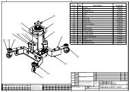
SPARE PARTS LISTFIG.1 BASEFIG.2 ARMS15
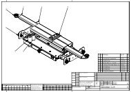
FIG.3 MECHANICAL SAFETY DEVICES - PISTONSFIG.4 PLATFORM16
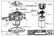
FIG.5 CONTROL BOX17
FIG.6 ELECTRIC CARDFIG. 7 ELECTRIC SAFETY DEVICES18
FIG.8 HYDRAULIC AND PNEUMATIC ALIMENTATION PIPESFIG.1 BASEN. CODE DESCRIPTION 30EP 25ET 30ET1 01-1100 BASE 2 2 22 03-3007 14X50 BOLT 8 83 03-3011 M14 NUT 8 84 03-3034 SELF LUBRICATING BUSHING 30X34X30 4 4 4FIG.2 ARMS1 01-1109 LOWER INSIDE BOOM 2 2 22 01-1110 LOWER OUTSIDE BOOM 2 2 23 01-1112 UPPER OUTSIDE BOOM 2 24 01-1111 LOWER INSIDE BOOM 2 24 01-2545 UPPER INSIDE.P1 BOOM 15 01-2454 UPPER INSIDE.P2 BOOM 16 01-2547 LEFT UPPER OUTSIDE BOOM 27 01-2555 RIGHT UPPER OUTSIDE BOOM 28 02-3004 BASE FASTENING PIN 8 8 89 03-3022 30 MM. SNAP RING FOR SHAFTS 8 8 810 02-3003 BOOM FASTENING PIN 8 8 811 02-3002 BOOM COUPLING PIN 8 8 812 03-3034 SELF LUBRICATIN BUSHING 30X34X30 32 32 3213 03-3021 SELF LOCKING NUT 24 24 2414 02-3005 ROLLER 8 8 815 02-3006 ROLLER 8 8 8FIG.3 MECHANICAL SAFETY DEVICES - PISTONS1 02-0222 FULL AIR PISTON 2 2 22 03-3013 M6 NUT 4 4 43 03-3506 WASHER 4 4 44 05-5000 90° UNION ELBOW 2 2 25 03-3014 M10 NUT 2 2 26 05-5006 AIR TDUOP O’RING 2 2 27 02-1022 WASHER 2 2 28 02-2001 SHAFT FOR AIR PISTON 2 2 29 02-2000 CYLINDER FOR AIR PISTON 2 2 210 03-3019 M6X16 TSPEI BOLT 4 4 411 01-1020 MECHANICAL SAFETY DEVICE HOCK 2 2 212 01-1018 P1 MECHANICAL SAFETY DEVICE 1 1 113 01-1019 P2 MECHANICAL SAFETY DEVICE 1 1 114 01-1021 PISTON HOLDER 2 2 215 03-3017 M10X20 BOLT 4 4 416 04-4000 P1 PISTON 1 1 117 04-4001 P2 PISTON 1 1 118 04-4202 P1 PISTON GASKET KIT 1 1 119 04-4203 P2 PISTON GASKET KIT 1 1 120 03-3023 35 MM. SNAP RING FOR SHAFT 8 8 821 02-3001 PISTON FASTENING PIN 4 4 422 03-3035 35X39X20 SELF LUBRICATING BUSHING 8 8 823 04-4548 PARACHUTE VALVE 3/8 2 2 219
FIG. 4 PLATFORM1 01-2537 PLATFORM 22 01-2502 RED PLATFORM 2 25 01-2601 RED RIGHT EXTENSION (ON FLOOR) 16 01-2602 RED LEFT EXTENSION (ON FLOOR) 17 01-0114 RIGHT EXTENSION (IN FLOOR) 18 01-0113 LEFT EXTENSION (IN FLOOR) 19 01-0116 RIGHT EXTENSION (IN FLOOR) 110 01-0115 LEFT EXTENSION (IN FLOOR) 111 01-4006 WHEEL TRIMMING 212 01-4021 WHEEL TRIMMING 1 113 02-2220 EXTENSION PIN 2 214 03-3506 WASHER 4 4 415 03-3003 TCEI M5X10 BOLT 28 28 2819 03-3034 SELF LUBRICATING BUSHING 30X34X30 4 4 420 03-3007 M15X50 BOLT 421 03-3011 M14 BOLT 4FIG. 5 CONTROL BOX1 06-6012 FINISHING ELEMENTS 1 1 12 06-6002 MAIN SWITCH 1 1 13 01-1123 CABINET 1 1 14 06-6003 SIGNAL LIGHT 1 1 15 06-6004 PROTECTION CAPS 1 1 16 06-6005 PILOT LAMPS 1 1 17 06-6007 ACTUATOR BUTTON COVER 4 4 48 06-6009 CONTACT ELEMENT 4 4 49 05-5512 6X4 90° UNION ELBOW 1/8 RATIO 1 1 110 05-5000 AIR ELECTRO-VALVE 1 1 111 05-5514 AIR ELECTRO-VALVE CAP 1 1 112 01-1738 SIDE DOOR 1 1 113 06-0999 FULL ELECTRIC CARD 1 1 114 01-1737 FRONT DOOR 1 1 115 06-6000 THREE PHASE MOTOR 1 1 116 06-0666 PUMP MOTOR UNIT 1 1 117 01-1026 OIL TANK 1 1 118 04-4024 TANK CAP 1 1 1FIG.6 ELECTRIC CARD1 06-6010 TRANSFORMER 50VA 1 1 12 06-6011 CONTACTOR 24VA 1 1 13 06-6013 RELAY 24VAC 1 1 14 06-6014 RELAY BASE 1 1 15 06-6016 5X20 2A FUSE 1 1 16 06-6017 5X20 500 mA 1 1 17 06-6018 PRINTED CARD 1 1 18 06-6520 RELAY 24VDC 2 2 29 06-6523 FUSE CARRIER 2 2 210 06-6537 WEBER FUSE 20A 3 3 311 06-6621 RELAY BASE 2 2 212 06-6536 25A TRIPOLAR FUSE CARRIER 1 1 1FIG.7 ELECTRIC SAFETY DEVICES3 01-1038 RIGHT FOOTGUARD 14 01-1028 LEFT FOOTGUARD 15 01-1156 RIGHT FOOTGUARD (ON FLOOR) 16 01-1155 RIGHT FOOTGUARD (ON FLOOR) 17 01-1151 RIGHT FOOTGUARD 18 01-1151 LEFT FOOTGUARD 19 01-2615 RIGHT FOOTGUARD (ON FLOOR) 110 01-2616 RIGHT FOOTGUARD (ON FLOOR) 113 01-1001 RIGHT FOOTGUARD SPRING SUPPORT 4 3 314 01-1002 LEFT FOOTGUARD SPRING SUPPORT 4 3 315 03-3002 L140 SPRING 4 4 416 N.C. L 130 SPRING 4 2 219 01-1106 BRACKET PHOTOEL.CELL CUT OUT 1 1 120 01-0248 BRACKET 20X40 3 3 324 01-1003 FOOTGUARD ADJUSTING MS BRACKET 2 2 226 01-1004 FOOTGUARD DRIVING MS BRACKET 2 2 227 06-6600 PHOTOELECTRIC CELL 1 1 128 06-6003 REFLECTOR 1 1 129 06-6508 MICRO SWITCH MS 54 1 1 130 06-6135 MICRO SWITCH MS 10 1 1 131 06-6133 MICRO SWITCH TZ7310 2 2 232 06-6034 MICRO SWITCH FR 502 1 1 1FIG.8 HYDRAULIC AND PNEUMATIC ALIMENTATION PIPES1 04-4564 F R1 PIPE 1 1 12 04-4560 B R1 PIPE 1 1 13 04-4562 E R2 PIPE 1 1 14 04-4563 D R1PIPE 1 1 15 04-4559 A R2 PIPE 1 1 16 05-5502 RILSAN WHITE AIR PIPE X X X20
7 04-4561 C R2 PIPE 1 1 121
SCISSOR LIFT FREE WHEESMAINTENANCE BOOK<strong>GEMINI</strong>INITIAL TESTN. DESCRIPTION TEST YES NO Notes1 Floor consistency check2 Safety distances check (from walls, columns, ceiling, other machines etc.)3 Power supply line check.4 Pneumatic supply line check.5 Lift levelling check.6 Lift working check.7 Mechanical safeties working check.8 Electric safeties working check.9 Loaded lift check.10 Lift fixing check.11 Oil level check.12 Hydraulic failure check.13 Pneumatic failure check.14 Operating instructionNOTESInstallerUserStamp and signatureStamp and signatureDateNext test on:22
RECURRING OR OCCASIONAL VISITN. DESCRIPTION OF TEST YES NO Notes1 Lift maintenance and cleaning check.2 Mechanical safeties working check.3 Electric safeties working check.4 Oil level check.5 Rollers slides fattening.6 Movable parts fattening.7 High pressure flexible pipes check.8 Hydraulic failure check.9 Pneumatic failure check.10 Lift levelling check.11 Loaded lift check.NOTESResult of visitPositiveNegativeInstallerUserStamp and signatureStamp and signatureDateNext test onRECURRING OR OCCASIONAL VISITN. DESCRIPTION OF TEST YES NO Notes1 Lift maintenance and cleaning check.2 Mechanical safeties working check.3 Electric safeties working check.4 Oil level check.5 Rollers slides fattening.6 Movable parts fattening.7 High pressure flexible pipes check.8 Hydraulic failure check.9 Pneumatic failure check.10 Lift levelling check.11 Loaded lift check.NOTESResult of visitPositiveNegativeInstallerUserStamp and signatureStamp and signatureDateNext test on23
TESTS TO BE MADE BY THE USERTESTS DURING USE1 Levelling check.2 Hydraulic failure check.3 Pneumatic failure check.4 Safety devices working check.MONTLY TESTS1 Lift through cleaning.2 Rollers slides check.3 Cylinders air bleeding (if necessary).HALF-YEARLY TESTS1 Oil level check.2 High pressure flexible pipes check.IN CASE OF ANOMALY, STOP THE LIFT ANDCONTACT OUR SERVICE DEPARTEMENT IMMEDIATELY24
FAILUREREPAIRACTIONDateStamp and signatureFAILUREREPAIRACTIONDateStamp and signatureEDITION MAY 1999 BY THE GRAPHIC DEPARTEMENT25