
You also want an ePaper? Increase the reach of your titles
YUMPU automatically turns print PDFs into web optimized ePapers that Google loves.
PrefaceThis booklet was prepared under the direction of the Committee on Research of the American Institute of SteelConstruction, Inc. as part of a series of publications on special topics related to fabricated structural steel. Itspurpose is to serve as a supplemental reference to the <strong>AISC</strong> Manual of Steel Construction to assist practicingengineers engaged in building design.This document is intended to provide guidelines for the design of braced and unbraced frames with partiallyrestrained composite connections (PR-CCs). The design procedures and examples in this guide represent arefinement of the work presented by Ammerman and Leon 7 ' 8 and is thoroughly documented in more recent workby the authors. 12,21 The design of structures utilizing PR-CCs for gravity and wind loads falls under the provisionsof Section A2.2 of the LRFD Specification for Structural <strong>Design</strong> of Buildings. <strong>Design</strong> for seismic loads is allowedunder Section 7.4.1 of the latest version of the NEHRP provisions.The guide is divided into four parts. The first part is an introduction dealing with topics pertinent to partiallyrestrained (PR) analysis and design, and discusses some of the important design choices utilized in the designprocedures and examples. The second part contains detailed, concise design procedures for both braced andunbraced frames with partially restrained composite connections. The third part consists of a detailed designexample for a four-story building. The design is for an unbraced frame in one principal direction and for a bracedframe in the other. The fourth part contains design aids in the form of Tables and Appendices.It is important that the reader recognize that the guide is intended to be a self-contained document and thus islonger than comparable documents dealing with similar topics. The reader is advised, on a first reading, to readParts I and III carefully, consulting Part IV as necessary. Once the reader is familiar with the topic, he/she willonly need to consult Parts II and IV in doing routine design work.The design guidelines suggested by the authors that are outside the scope of the <strong>AISC</strong> Specification or Code donot represent an official position of the Institute and are not intended to exclude other design methods andprocedures. It is recognized that the design of structures is within the scope of expertise of a competent licensedstructural engineer, architect, or other licensed professional for the application of principles to a particular structure.AcknowledgmentsThe authors would like to thank the following people who have been very helpful in the writing of this designguide and have also been key players in its development: Heinz Pak, former Manager of Building Engineering for<strong>AISC</strong>, initiated and sponsored the guide; Larry Kloiber of LeJeune Steel provided input particularly in the practicalfabrication aspects of the connection; Dave Galey, Zina Dvoskin, and Johanna Harris of HGA's StructuralEngineering Department who helped developed the first draft of this guide and provided invaluable input andassistance throughout the project; Bob Lorenz, Director of Education and Training, and Nestor Iwankiw, VicePresident of Technology and Research for <strong>AISC</strong>, whose patience and support made this document possible.The information presented in this publication has been prepared in accordance with recognized engineeringprinciples and is for general information only. While it is believed to be accurate, this information should not beused or relied upon for any specific application without competent professional examination and verification ofits accuracy, suitability, and applicability by a licensed professional engineer, designer, or architect. Thepublication of the material contained herein is not intended as a representation or warranty on the pan of theAmerican Institute of Steel Construction, Inc. or the American Iron and Steel Institute, or of any other personnamed herein, that this information is suitable for any general or particular use or of freedom infringement of anypatent or patents. Anyone making use of this information assumes all liability arising from such use.© 2003 by American Institute of Steel Construction, Inc. All rights reserved.This publication or any part thereof must not be reproduced in any form without permission of the publisher.
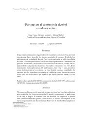
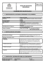
Part IBACKGROUND1. INTRODUCTIONPartially restrained connections, referred to as PR connectionsin the LRFD provisions 1 and Type 3 connections in theASD provisions, 2 have been permitted by the <strong>AISC</strong> Specificationssince 1949. With some notable exceptions, however,this type of connection has not received widespread applicationin practice due both to (a) the perceived complexity ofanalysis required, and (b) the lack of reliable information onthe moment-rotation characteristics of the connections asrequired by design specifications. The notable exceptionsinvolve specific types of connections that have been demonstrated,through experience in the field and extensive analyticalwork, 3,4to provide equivalent response under designconditions to that of rigid connections. The Type 2 or "wind"connections allowed under the ASD provisions are a goodexample of this approach. In these cases the specificationessentially prequalifies a simple connection under gravityloads as a rigid connection under lateral loads. In reality, ofcourse, these connections are neither fully rigid (FR) norsimple but partially restrained (PR). The code uses this artificeto simplify the analysis and design, but requires a guaranteedrotational and strength capacity from these connections.After 10 years of research and development a new type ofsemi-rigid connection, labelled the Partially Restrained CompositeConnection or PR-CC,* can be added to this list. 5-12 Theword "composite" is used to indicate that this connectionengages the reinforcing steel in the concrete slab to form thetop portion of the moment resisting mechanism under bothlive loads and additional dead loads applied after the end ofconstruction (Figure 1). The bottom portion is typically providedby a steel seat angle with web angles providing theshear resistance. This connection may be used to economizebeam sizes for gravity loading or to resist lateral loads inunbraced frames. The design of this type of system is basednot only on the work of the senior author at the University ofMinnesota, 5-12,21 but also on that of many researchers throughoutthe U.S. and Europe. 11,13-19 The extensive experimentalwork required in the development of these connections isdiscussed elsewhere 5 ' 6 ' 9 and will not be repeated here.Part I of this design guide is organized as follows. First,some discussion of partially restrained connection behaviorwill be given to put PR-CC design in its proper context.Second, the advantages and limitations of PR-CCs are discussedin the context of simplified or code-oriented design.Third, the assumptions and theory applied in their design aredescribed. Fourth, detail recommendations for the connectionsunder both gravity and lateral loads are given. In Part IIa step-by-step procedure is presented in outline form followedby corresponding detailed calculations for an example problemin Part III. The 1993 Load and Resistance Factor <strong>Design</strong>(LRFD) Specification 1 is used in the design and ASCE 7-93 20is used for load determination. Tables and design aids areincluded in Part IV to facilitate the design.2. CHARACTERIZATION OF CONNECTIONBEHAVIORThe behavior of structural connections can be visualized fordesign purposes with the aid of moment-rotation curves(Figure 2). These curves are generally taken directly fromindividual tests or derived by best-fit techniques from theresults of multiple tests. 22,23 All design specifications requirethat the structural engineer have a reliable curve for thePR connections to be used in design since such curves syn-Fig. 1. Partially restrained composite connection (PR-CC).* The label PR-CC is meant to encompass the connections previously labelled semi-rigid composite connections (SRCC) by the senior author.1© 2003 by American Institute of Steel Construction, Inc. All rights reserved.This publication or any part thereof must not be reproduced in any form without permission of the publisher.
the size the connection's main characteristics: stiffness,strength, and ductility. 6 The application of PR-CCs to designimplies that reliable relationships have been developedand are simple enough to use in design. The equationsdeveloped for SRCCs will be discussed in detail in Section 4.In Figure 2(a), the stiffness of the connection correspondsto the slope of the curve. For most connections, such asPR-CCs, the slope changes continuously as the moment increases.The real stiffness of the connection at any stage ofthe curve corresponds to the tangent stiffnessHowever, for design purposes it is customary toassume a linear approximation for the service rangegenerally in the form of a secant stiffnessThis stiffness is generally less than the initial stiffness of theconnections (K i), and corresponds closely to the unloadingstiffness (K unloading).Based on the initial (K ior service stiffness (K conn), connec-Fig. 2. Characterization of connection behavior.tions can be classified as fully restrained (FR), partiallyrestrained (PR) or simple depending on the degree of restraintprovided (Figure 2(b)). The current approach in design is toassume that for members framing into relatively rigid supports,if the connection stiffness is about 25 times that of thegirder (i.e,> 25), the connection can be consideredrigid. Conversely, if the connection provides a stiffnessless than 0.5 times that of the girder, then it should beconsidered simple.* The classification by stiffness is validonly for the service load range and for connections which donot exhibit significant non-linear behavior atInsofar as strength is concerned, joints can be classifiedeither as full strength (FS) when they are capable of transferringthe full moment capacity of the steel beam framing intothem or as partial strength (PS) when they are not (Figure2(b)). The schematic moment-rotation curve for a PR-CCshown in Figure 2(b) does not reach the full capacity, andthus is a partial strength connection. Partial strength is desirablein seismic design because it permits a calculation of themaximum forces that a structural element will be required towithstand under the uncertain ground motions that serve asan input. If the designer knows what is the maximum momentthat a connection can transmit, he/she can insure that otherkey elements, columns for example, remain elastic and sufferno damage even when the seismic input far exceeds the codeprescribed forces. This design philosophy, known as capacitydesign, 24 is employed in this design guide. Capacity designrequires that any hinging region be carefully detailed todissipate energy and that all other elements in the structureremain basically elastic when the maximum plastic capacityof these regions is reached. Following this design philosophy,the detailing of the PR-CCs is driven by the need to providea stable, ductile yielding mechanism such as tension yieldingof the angle legs rather than a sudden, brittle failure such asbolt shearing.Ductility is required in structural design so that somemoment redistribution can occur before the connection fails.In applications for unbraced frames, and particularly if seismicloads are important, large ductilities are required. Ductilitiescan be defined in relative terms or ultimaterotation capacity divided by a nominal yield one, see Figure2(a)) or in absolute terms 0.05 radians, for example).The required ductilities are a function of the structural systembeing used and whether large cyclic loads need to be consideredin the design. In general cyclic ductilities greater than 6(relative ductility) or 0.035 radians (absolute ductility) aredesirable for frames with PR-CCs designed in areas of low tomoderate seismic risk. Demands in unbraced frames for areaswhere wind governs the design or for braced frames are lower.* The values of 25 and 0.5 selected here were chosen arbitrarily; ranges from 18 to 25 for the FR limit and 0.2 to 2 for the simple limit are found in the literature. The selection ofspecific values is beyond the scope of this guide. These values are cited only for illustrative purposes.2© 2003 by American Institute of Steel Construction, Inc. All rights reserved.This publication or any part thereof must not be reproduced in any form without permission of the publisher.
The PR-CCs described in this guide meet the criteria for areasof low to moderate seismic risk and can be used for the otherdesign conditions described above.It is important to recognize at the outset that for designpurposes an exact, non-linear moment-rotation curve such asthose shown in Figure 2 may not be necessary. In fact, onlytwo important points need to be known for design. The firstcorresponds to the serviceability level where the stiffness,K conn, must be known for deflection and drift calculations. Thesecond point is the ultimate strength (M ult) and rotationachievable by the connection to insure that adequate plasticredistribution of stresses can occur.3. ADVANTAGES AND LIMITATIONSThere are several practical advantages to PR-CCs. By usingreinforcing in the slab the need for a top angle or top plate iseliminated. This provides a more economical solution forseveral reasons:(a) The top force and moment arm are increased resultingin either (1) a reduction of the forces in the connectionfor a given design moment, or (2) an increase in theconnection moment capacity. The difference in strengthcan be substantial because the ultimate capacity of aseat angle in tension is only about one-third of itscapacity in compression (area of its leg times its yieldstress). Thus an A 36 ½-in. top angle 8-in. wide (totalforce = 8 x 0.5 x 36 x 0.33 = 48 kips) can be replacedwith four #4 Grade 60 reinforcing bars (total force = 0.2x 4 x 60 = 48 kips). The capacity of the connection canthen be controlled by the amount of steel in the slab. Inaddition, in a floor system with shallow beams (sayW14s or W16s) the increase in moment arm (Y3) canadd 20 to 25 percent additional capacity.(b) In gravity design PR connections result in an efficientincrease of the end moments. For a composite section,the strength in positive bending is typically on the orderof 1.8 times that of the steel beam alone (Mp). Under auniformly distributed load, if simple connections areused, the structural efficiency of the system is lowbecause the large capacity of the system is required onlyat the centerline; most of the section strength is wasted.Similarly, if rigid connections are used the efficiencyof the composite system is considerably reduced becausethe end moments (wL 2 /12) are large where thesection strength is small (M p ), and the midspan momentsare small (wL 2 /24) are small where the sectionstrength is large (1.8Mp). Only the use of semi-rigidconnections and composite action allows the designerto "balance" the connection such that the demand (externalmoment) is balanced by the supply (section capacity).(c) The use of PR-CCs reduces the required beam sizeand/or reduces deflection and vibration problems becauseof the composite action provided by the slab. Theuse of reinforcing bars, as opposed to the common steelmesh used for temperature and shrinkage crack control,is neceesary to achieve these benefits. The use of distributedsteel reinforcing bars around the columns considerablyreduces crack widths over beam and columnlines.(d) From the construction standpoint the need to cut andresupport the steel decking around the support is eliminated.The placement of some additional reinforcingbars in the slab should not represent significant additionalcosts.Connection research on PR frames until recently consideredonly bending about the strong axis of wide flange columns.In this guide some preliminary recommendations for extendingtheir use to the weak axis of columns in braced frames aregiven. When used on the weak axis the web angles aretypically not used and the connection strength is reducedslightly. In general a stiffened seat is used to help carry theshear force in this situation.Because of its increased flexibility relative to rigid (Type1 or FR) connections, the system is most applicable in structuresthat are ten stories or less, and it should be limited to usewith lateral wind forces or seismic loading with groundaccelerations less than or equal to 0.2g only, pending furtherresearch.It should also be clear that PR-CCs cannot, in general, beused as substitutes for rigid connections on a one-to-one basis.This implies that more connections will have to participate inresisting the lateral loads in a SRCC frame. The key to theeconomy of the system is that it allows the designer to turnsimple connections into semi-rigid ones by adding only slabsteel. The latter is inexpensive and is already being used bymany designers to control cracking over column lines. Thusthe additional costs for material and labor will be small. Thegains in structural efficiency and redundancy will far outweighthe additional construction costs. The recent experiencewith the Northridge earthquake clearly points out theneed for redundancy and ductility in steel lateral load resistingsystems. PR-CCs clearly provide a superior level of performancein this respect and can be adopted as a secondarylateral-load resisting system in areas of high seismic risk andas the primary system in areas of low to moderate seismicrisk.4. CONNECTION CURVESThe most accurate way of modelling the behavior of asemi-rigid connection such as that shown in Figure 2 isthrough either a continuous exponential or a piecewise linear3© 2003 by American Institute of Steel Construction, Inc. All rights reserved.This publication or any part thereof must not be reproduced in any form without permission of the publisher.
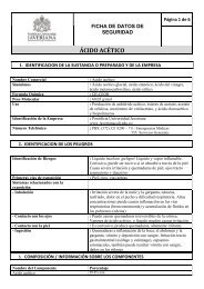
function. In advanced computer programs, spring elementswith similar characteristics can be input at the ends ofthe beams to simulate the behavior of the connections. Framescan then be analyzed under a variety of load combinationsand the second order effects included directly through the useof a geometric stiffness matrix.The design procedure proposed here simplifies the analysisto a two-level approach:(a) a first order elastic analysis with linear springs atservice to check beam deflections and frame drift.These results will be extended to the case of factoredloads in order to check the beam-column strength equations.(b) a simplified second-order, rigid-plastic analysis with aweak beam-strong column mechanism will be used tocheck ultimate strength and stability of the frame.The first level is very similar to what would be used today fora rigid frame design. Many commercially available computerprograms incorporate linear springs and thus thistype of analysis is well within reach of the average practitioner.The second level is used here as opposed to the conventionalBl and B2 approach for frame stability because thedevelopment of that technique for PR frames, and for framesusing PR-CCs in particular, is still underway. 25 Several otheralternatives, including (a) a rigorous analysis that modelsboth the non-linearities in the connections and the effectsdirectly, or (b) an analysis with linear springs, using a secantstiffness to are possible. The second-order plastic analysisdescribed here is useful for preliminary design. The finaldesign should be checked using advanced analysis tools if thegeometry of the frame is not regular with respect to verticalFig. 3. Completecurve for a typical PR-CC.and horizontal stiffness distribution. The simplifications requiredto carry out this two-level approach will be discussedin Section 5.As noted earlier, specifications require that the engineerhave a good idea of the strength and stiffness characteristicsof these connections before he/she utilizes them in design. ForPR-CCs, the work of Leon et al. 5,26,27 has led to the followingexpression for the curve under negative bending (slabsteel in tension):whereC1 = 0.18(4 x A sF yrb+ O.857A lF y)(d + Y3)C2 = 0.775C3 = 0.007(A l+ A wl)F y(d+Y3)= girder end rotation, radiansd = girder depth, in.Y3 = distance from the top flange of the girder to thecentroid of the reinforcement, in.A s= steel reinforcing area, in. 2A l= area of bottom angle, in. 2A wl= gross area of double web angles for shear calculations,in. 2F yrb= yield stress of reinforcing, ksiF y= yield stress of seat and web angles, ksiSince the connection behavior is not symmetrical with respectto either strength or stiffness, a similar expression is neededfor positive bending (bottom angle in tension):whereCl = 0.2400 x [(0.48 x A wl+ A l]x(d+Y3)xF yC2 = 0.02Wx(d+Y3/2)C3 = 0.0100 x (A wl+ A l)x(d+Y3)xF yC4 = 0.0065 x A wlx (d +Y3) x F yThese curves were derived from tests and FE parametricstudies. 5-6,26-27 The complete curve given by Equations 1 and 2for a typical PR-CC is shown in Figure 3. This correspondsto a connection of a W18x35 A36 beam with 8 #4 Grade 60bars in the slab. The bottom angle area is 2.38 in. 2 and the areaof the web angles is 4.25 in. 2 The effective depth is 17.7 inchesassuming Y3 equal to 4 inches.Fortunately, experience has shown that PR-CCs in unbracedframes seldom unload into positive moment evenunder the full factored loads. Thus use of Equation 1 isjustified for the service load level and up to the factored loads.Equation 1, however, is still cumbersome for use in design.Given the detailing requirements for capacity design describedin Section 7, it is more practical to develop designtables for specific connections. Such tables are shown asTables 1 and 2, which contain all the necessary design infor-(2)4© 2003 by American Institute of Steel Construction, Inc. All rights reserved.This publication or any part thereof must not be reproduced in any form without permission of the publisher.
mation for a series of "prequalified connections."* In thisguide all the connections designed are "prequalified connections"which have been checked for a large number of failuremechanisms and loading conditions.Table 1 shows some of the key values to be used in design:the ultimate strength of the connection and the stiffnessfor checking drift (K-lat). Table 1 is divided into two parts,showing values for both angles with 36 ksi and 50 ksi nominalyields. In these tables Y3 is the distance from the top flangeof the beam to the centroid of the slab steel. The derivation ofthe values in Tables 1 and 2 are discussed in the next section,while the detailing is discussed in Section 7.5. ANALYSISOnce the characteristics are known the next problem ishow to analyze frames containing such connections. In thissection the analysis and design assumptions used in the designexamples (Part III) will be discussed.5.1 Service Load RangeThere are several ways to evaluate the performance of beamswith PR connections under gravity and lateral loads. Theyrange from using modified slope-deflection or moment distributionequations to using elements with non-linear springsin a computer program that incorporates effects directly.The following observations are pertinent:(a) The latest versions of the better commercial structuralanalysis packages (stiffness-based methods) allow designersto specify linear springs at the ends of beamelements. <strong>Design</strong> procedures should strive to use theseelements since the availability of multi-linear or fullynon-linear (exponential) spring elements in these softwarepackages is not foreseen in the near future.(b) While the behavior of the connections is non-linear, theuse of a secant stiffness up to about 2.5 milliradians ofrotation does not introduce significant error in the forceor displacement calculations. Thus the use of linearspring is justified for design of PR-CCs provided thedesigner keeps in mind that this approach will probablyoverestimate the forces at the connections but underestimatethe deflections.(c) Modified slope-deflection, moment distribution, andsimilar classical approaches, while of great value forthose familiar with their implementation, are tediousand prone to errors. 17(d) For those interested in gaining a better insight intoconnection behavior, a beam-line analysis, described indetail below, is the preferred method. Note that use ofthe beam line technique is not advocated for design; itis merely a great educational tool and it is used here inthat vein.In both (a) and (c) above the only unknown is the stiffness tobe assigned to the connections. From a simple rigid-plasticanalysis where (a) all rotations are lumped at the PR jointsand column bases, and (b) a strong column-weak beammechanism is assumed, it can be shown that the rotation isproportional to the allowable drift. For an allowable drift ofH/400, the corresponding rotation is 0.0025 radian or 2.5milliradians. Since the deformations of the beams and columnsare not included in this calculation, this value overestimatesthe rotations of the connections. This simplified analysisdoes not include any effects which are expected to benegligeble at this level even for PR frames. From experiencewith PR-CCs, it appears that to check service drifts a secantstiffness measured at a rotation of 2 milliradians is sufficientlyconservative to avoid too many redesign iterations. The valuesof the stiffness for drift calculations for the "prequalifiedconnections" are shown in Table 1 as K-lat. Note that thesecant stiffness used is different from the tangent stiffness thatwould be obtained by differentiating Equation 1 directly andsubstituting a value of = 0.002 radians.Following a similar line of reasoning, one could deriveconservative values for deflections under gravity loads. Assumingan allowable vertical deflection of L/360, a value of= 0.0025 seems reasonable. Solving Equation 1 for themoment (Ml) at the service rotation leads to a similar stiffnessfor gravity loads (K-grav = Ml/0.0025). These moments, Ml,are tabulated in Table 2, Part IV, for the "prequalified connections".Table 2 is given for different values of Y3 and isdivided into connections for braced and unbraced framesbecause the detailing requirements differ as will be describedlatter. The reader is cautioned not to confuse K-lat, the connectionstiffness for lateral drift, with K-grav, the connectionstiffness for live load deflections. While the difference in therotations at which they are calibrated is small, this effect hasbeen integrated directly into the design procedure.5.2 Beam Line Analysis for Gravity Loading at ServiceThe connection must be designed to resist the support momentsresulting from gravity loads after the slab has cured andthe member is acting as a composite beam. The magnitude ofnegative gravity moment will always be less than that assuminga fully rigid connection and is dependent on the stiffnessof the connection. This can be determined by a beam-lineanalysis. The three key elements for the beam-line analysisare the moment-rotation relationship of the connection, the* The tables are included at end of this guide (Part IV) and are kept separate from the text to facilitate their use in later designs.5© 2003 by American Institute of Steel Construction, Inc. All rights reserved.This publication or any part thereof must not be reproduced in any form without permission of the publisher.
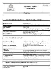
simply supported end rotation of the beam, and the fixed endmoment assuming a fully rigid connection of the beam. Notethat the beam line as defined herein is only applicable in theelastic range.The moment-rotation relationship for one of the typicalconnections in Table 1 (W18×35 with 8 #4 bars, Y3 = 5 in.,F y= 36 ksi) is shown as a solid line in Figure 4. To simplifythe beam line analysis the moment-rotation relationship willbe reduced to a linear spring. The linear spring is representedin Figure 4 by the dashed line. The corresponding stiffness isgiven by K-grav = = 147/0.0025 = 58,800 kip-ft/radian.The values of Ml, again, are tabulated in Table 2.Two values are needed to define the beam line: the fixedend moment, M F , and simply supported end rotation,These values can be determined by conventional beam analysismethods such as slope deflection, virtual work, or momentarea, or can be found in reference tables for most loadingpatterns. These values have been tabulated for the mostcommon loading patterns in Table 3, Part IV. The fixed endmoment depends on whether the connection at the other endis PR or pinned. If the far end restraint is PR then thefixed-fixed end moment (M ff) is used and if it is pinned thefixed-pinned end moment (M fp) is used. With the above keyelements established, two lines can be drawn, and the intersectionof those lines will provide the actual moment androtation under gravity loading as shown in Figure 4. Thisintersection point can be solved directly by an equation whichresults from the solution of simultaneous equations for thetwo lines in the beam line analysis. The equation of theconnection line is:The equation for the beam line is:The value of at the intersection of these lines is given by:The exact solution, the intersection of the solid line and thebeam line, can be obtained by setting Equations 1 and 4 equalto one another and solving for This is tedious and generallyyields a value very close to that from the linear approximation.Therefore the use of the exact solution is not warrantedfor preliminary design purposes.(3)(4)(5)5.3 Connection Ultimate Strength (Gravity Loads)The ultimate capacity of the connection is based on work byKulkarni. 26 A resistance factor of 0.85 is recommendedand is the same value used for composite beam design inChapter I of the LRFD Specification. M2 in Figure 4 andTable 2 is the moment which corresponds to a rotation, of20 milliradians. Most of the connections tested have reachedand exceeded this value. Considerable connection yieldingand deformation is present at this stage. This moment isincluded in Figure 4 and the design tables for two reasons.First, it illustrates the ductility of the connections. Second, ifthe user has software which allows a bi-linear spring to beinput for connections, M1 and M2 are useful values whichallow a bi-linear curve to approximate the actual curve.The connection ultimate strength is defined in both thepositive and negative directions. The negative bending ultimatestrength when the bottom angle is in compression,is:The positive bending ultimate strengthis:(6)(7)Fig. 4. Beam line analysis.The area of the angle, A l , is equal to the width of the horizontal6© 2003 by American Institute of Steel Construction, Inc. All rights reserved.This publication or any part thereof must not be reproduced in any form without permission of the publisher.
leg times the thickness of the angle leg. The area A wlis equalto the gross area of the web angles in shear, and A sis the totalarea of steel reinforcing provided in the concrete slab over awidth not to exceed seven times the steel column width. Thevalues from Equation 6 evaluated at 10 milliradians andincluding a factor of 0.85 are tabulated for the differentconnections in Table 1 as These values have beenarbitrarily selected as the design strength for these connections.The connection can also be used in braced frames withoutweb angles. This would be a simple modification from thecurrent seated beam design useful in designing connectionsto the weak axis of a column. The bottom angle required forthe seated beam would generally be adequate to supply thebottom part of the force couple and a small amount of reinforcementin the slab would provide the top force. The seatangle would need to be thickened or stiffened as needed totake care of the shear force. The ultimate capacity of thisconnection is:Tables 1 and 2, Part IV, provide key information regarding themoment-rotational relationship, ultimate moment capacity,and connection stiffness for a series of typical connectiontypes using steel reinforcement ranging from an area of 1.2in. 2 to 3.1 in. 2 and beam depths from 12 to 24 inches. Theconnections selected meet the criteria of explained above plusthe detailing requirements discussed in the next section. Theforce given in the tables is for the design of bolts or weldsbetween the beam bottom flange and angle.5.4 Frame and Beam Ultimate StrengthUltimate strength checks will be made for both individualbeams and the frame as a whole using plastic analysis. 28-30 Theapplicable load combinations for ultimate beam capacityfrom ASCE 7-93 are:(8)(9)Commonly the most critical load combination is given byEquation 10. The load factors for beam mechanisms of fourdifferent common load cases and for three different connectionrelationship are shown in Table 4. The general form forthese load factors is:where(16)is the load factor,the coefficients given in Table 4, Part IV,are the negative bending ultimate designcapacities of connections 1 and 2,andis the ultimate moment capacity of thecomposite beam in positive bending.5.4.2 Frame Ultimate CapacityAn approximate second order rigid plastic analysis is carriedout to determine the overall adequacy of the frame. Thecontrolling combination is generally given by Equations 12or 13. The collapse mechanism governing this type of designis a weak girder-strong column one (Figure 5).In plastic analysis two possibilities, proportional and nonproportionalloading, arise. Proportional loading, in whichboth the lateral and gravity loads are increased simultaneously,is commonly used. This design procedure, however, iscalibrated to non-proportional loading. In this case the gravityloads are held constant and the lateral loads are increased.Thus, if Equation 12 or 13 is used, the gravity loads (D, L,L r, and/or S) are kept constant while the lateral loads (W or E)are increased from zero to failure. The multiplier on the lateralloads at failure is the ultimate load factor for the frame,To obtain the second order effects must be considered.(10)For frame ultimate capacity they are:(11)(12)(13)(14)(15)5.4.1 Beam Ultimate CapacityThe load combination used to calculate the beam load factoris the most critical of combinations given by Equations 9-11.Fig. 5. Plastic collapse mechanism.7© 2003 by American Institute of Steel Construction, Inc. All rights reserved.This publication or any part thereof must not be reproduced in any form without permission of the publisher.
Here an approximate method, called the mechanism curvemethod 28 is used. Before calculating the first order loadfactor must be calculated. The first order rigid plastic loadfactor, is calculated as:where is the moment capacity of a hinge or connection,V iis the factored lateral force at story i, and h tis the heightfrom the base to story i. In this equation the numeratorrepresents the internal resisting forces provided by all hingingregions, while the denominator represents the external loads.Thus any value of greater than one represents a safecondition. The summation of the connection design strengthsare over all the connections, while the summation of V ih iisfrom 1 to S, the number of stories.The calculation of the internal resisting moments requirescomputing the resistance provided by all elements hinging:the column bases, the external and the internal moments.Symbolically:whereIn this equation the summation of positive and negativemoment capacities assumes that the connections oneither side of each joint have reached their ultimate designcapacity. If the exterior connections are simple, then the lastterm above is zero. To account for the presence of axial loadon the plastic capacity of the base columns the followingapproach is used. If P u
the less stiff to more stiff connection and on the ratio of thesemi-rigid to the fixed-fixed end moment for the stiffer connection.If K ais the stiffness of the stiffer connection, the ratioof semi-rigid to fixed-fixed end moment can be expressed as:where(21)M FFand M SR= the fixed-fixed and semi-rigid end moments,respectively.For design purposes it is beneficial to assume a servicerotation for preliminary deflection requirements and thencheck that deflection after connections have been chosen byeither beam line analysis or from:(22)Using a 2.5 milliradian service rotation, the connection willadd an additional L/1600 to the deflection when the connectionstiffnesses are equal. If L/360 is the service limit, thisapproach now requires that the service load deflection basedon a fixed-fixed beam approach be kept below L/465.When the beam has one semi-rigid connection and onepinned connection the following equation provides a conservativedeflection for any connection stiffness:design of frames with PR-CCs takes advantage of the additionalstiffness in the beams provided by the composite action(see next section). Thus the additional flexibility due to thePR connections is balanced by a larger beam stiffness and thecolumn sizes need to be increased generally by only one ortwo sections.The flexibility of the column base plate connections shouldbe incorporated into these calculations. Drifts in the first floorwill probably control the design of many low-rise PR frames.As for unbraced FR frames, the assumption of full fixity atthe base should not be made unless careful analysis anddetailing of the column base plate justify it.6.3 Beam StiffnessIn modelling PR-CC frame behavior, the effective moment ofinertia of the beams (I eq ) should take into account the nonprismaticnature of the beam, i.e. the variation in moment ofinertia for a composite beam with SRCC between areas ofpositive and negative bending. The moment of inertia inpositive areas (I LB ) can be determined in the traditional wayfor composite beams and it is recommended that the lowerwhere(23)d FP= the beam deflection with one end fixed and the otherend pinned andQ = the actual rotation of the semi-rigid connection.The rotation Q may be found by a beam line analysis usingthe fixed-pinned end moment, M FP .6.2 Lateral DriftWhen used in unbraced frames, the flexibility of the connectionswill cause the lateral deflections of the frame to increaseover that which would occur if the connection was fully rigid.To illustrate this effect, the contributions of the columnsbeams and connections to the total driftcan be separated as illustrated in Figure 6.For preliminary design, the engineer can either estimate thesize of the columns based on experience or use a trial-and-errorapproach combined with a computer program. A handmethod to estimate the column sizes, based on the approachgiven in Figure 6, is included in Appendix A.In general the design of frames with PR-CCs does notrequire that the column sizes be increased significantly overthose used for an equivalent rigid frame. This is because theFig. 6. Components of PR frame drift.9© 2003 by American Institute of Steel Construction, Inc. All rights reserved.This publication or any part thereof must not be reproduced in any form without permission of the publisher.
ound tables in the LRFD Manual be used for its determination.The moment of inertia in the negative areas is afunction of the steel beam and the reinforcing in the slab. Thiscan be determined using the parallel axis theory. Table 7provides values for several combinations of reinforcing andbeam sizes for a Y3 (distance from the top flange to centroidof the reinforcing) equal to 3, 4, 5, and 6 inches.If the positive moment of inertia is denoted as and thenegative moment of inertia is denoted as then is the"prorated" average of the two. For beams with SRCC connectionsat both ends it is recommended that the followingvalue be used:When one end has a SRCC and on end pinned:6.4 PR Connection Effect on Column End Restraint(24)(25)PR connections reduce the amount of end restraint providedby the beams to the columns when compared to FR connections.This must be considered when carrying out stabilitychecks. The effective moment of inertia of a beam includingthe effect of the PR connections to be used in calculating Gfactors is: 25,31 (26)where(27)= are the beam length and equivalent moment ofinertia,= is the connection tangent stiffness, and C = 1for braced frames and C = 3 for unbraced ones.The main problem in utilizing this formula is that at thefactored load where stability is being checked must be knownfor each connection. Several simplifications to this approachhave been proposed:(a) For a frame subjected to lateral loads the connectionson one side of the column will continue to rotate in thesame direction as the rotations imposed by the gravityloads, while the connection on the other side will rotatein the opposite direction. 25,31For the connection thatcontinues to load, the stiffness of the connection willdecrease and in the limit (i.e. at very large rotations)this stiffness will be zero. The connections on the otherside of the column will unload along a path with astiffness close to the service level stiffness. In calculatingG one can then assume that for one side of theconnection the effective beam stiffness in Equation26 can be calculated by setting while for theother side This results in only one side of theconnection, the unloading side, contributing to G. Thisprocedure is overconservative.(b) A similar reasoning for braced frames implies that bothconnections are loading and that therefore their restraintto the column is negligible. For this case K=1.(c) For unbraced frames, a better, less conservative estimatecan be made by assuming that the loading connectionhas not reached its ultimate capacity. In this casethe stiffness of the loading side can be approximated asthe slope of a line connecting the service andultimate points. The stiffness for the unloadingside should still be taken as(d) Recently it has been suggested that the use of a secantstiffness to the ultimate point should alsoprovide a reasonable lower bound to the frame stability.In this case both connections are assumed to have thesame stiffness.(e) If an advanced anaylsis is carried out, then the K-factorscan be calculated in the usual manner by using anequivalent stiffness as given by:where(28)is calculated from Equation 27 using the tangent stiffness,andand are the changes in moment during the last stepin the loading at the far and near end of the element,respectively.For the design example, the stability was checked followingthe procedure described in (a). A more thorough treatment ofthis topic, including an example utilizing the same frame asin this design guide, can be found in. 31In Chapter 3 of thisreference, in addition, there is extensive treatment of theextension of the story-based stability procedures to PRframes.6.5 Bottom Angle ConnectionFor unbraced frames the bottom angle thickness should beincreased so that approximately the same stiffness is providedin the positive direction as the negative direction. To accomplishthis the yield force in the bottom angle, shouldbe at least 1.2 times the force in the reinforcement,assuming the angle width remains constant. For bracedframes the bottom angle is sized for a force equal toAs shown in Figure 1, the bottom angle is usually connectedto the bottom flange of the beam by ASTM A325 orA490 bolts. A 6-in. long angle leg can normally accept 4 bolts(2 rows of 2), but in some cases a 7- or 8-in. leg may benecessary. Bolt bearing and shear must be checked at ultimate10© 2003 by American Institute of Steel Construction, Inc. All rights reserved.This publication or any part thereof must not be reproduced in any form without permission of the publisher.
loading assuming some bolt slippage occurs. For serviceloading, however, it is important that the bolts not slip toensure that the spring stiffness response is maintained. Forthis reason, an additional check should be made for servicegravity and wind loading against the slip-critical shear valuesfor the bolts, and the bolts should always be fully tensioned.Welding the angle to the bottom flange can also be consideredfor large forces; in this case the serviceability check need notbe performed. Welding of the angle to the column is discouragedsince the ductility of the system depends on the abilityof the angle to deform plastically as a two member frame.For each set of reinforcement a set of bottom angles andbolts have been chosen that have passed all the requiredconnection checks by LRFD. These angles and bolts areshown in Table 8. The force in the bottom angle that wasdesigned for was based on the ultimate capacity design approach.Two of the same type of bolts as for the horizontal legwere used in the vertical leg of the angle for connections toresist tension in unbraced frames. Prying action of the anglewas considered. If any other angle and bolt set is used allconnection checks must be carried out.7. DETAILINGFor SRCCs, the authors and their co-workers have developedthe following recommendations (Figures 7 and 8):Fig. 7. Detailing requirements (plan view).Fig. 8. Detailing requirements (elevation).11© 2003 by American Institute of Steel Construction, Inc. All rights reserved.This publication or any part thereof must not be reproduced in any form without permission of the publisher.
(1) For designs where seismic forces control and a weakbeam-strong column mechanism is desirable:(29)In this equation the moment capacities of the columnsshould account for the decrease due to axial loads(Equation 18), while the moment capacity of the connectionsshould be increased by 1.25 to account for theoverstrength of the slab steel. The usual factors shouldbe included in this calculation, and thus the ratio ofnominal capacities should be greater than 1.6.(2) The longitudinal slab steel should be kept within acolumn strip less than or equal to seven column flangewidths. Tests have shown that the steel must be close tothe column to be activated at low drifts. Since the intentis to obtain a connection that is stiff at service loads, theplacement of the slab steel is a key detailing issue.(3) The slab steel should extend at least l dplus 12 inchespast the point of inflection or L/4, whichever is longest.At least two bars should be run continuously for unbracedframes governed by wind. At least two bars forthe case where wind governs or one half of the steel forthe case where seismic governs, should be run continuouslyfor unbraced frames since the point of inflectioncan change drastically under seismic loading(4) The bar size should be kept small (between #4 and #6),and at least three bars on either side of the columnshould be used.(5) Transverse steel must be provided at each column line,and must extend at least 12 inches into the slab strip. Toreduce serviceability problems a minimum of 0.05 in. 2of steel per lineal foot must be provided over thegirders, with this reinforcement extending at least 24inches or 30 bar diameters, whichever is greater, oneither side of the girder. Reinforcing transverse to thedirection of the moment connection serves a structuralpurpose and deserves attention. Moments imposed bylateral loads cause a transfer offerees from the reinforcingto the column by means of shear in the slab andbearing at the columns. The transverse reinforcing,therefore, acts as concrete shear reinforcing for thismechanism and it is recommended that the area of thetransverse reinforcing be made approximately equal tothe main reinforcing.(6) The development of the equations for curves forPR-CCs assumed that friction bolts (i.e., slip-critical)are used in the seat angle. The intent is not to preventslip at service loads, but to minimize it.(7) Full shear connection in the form of headed shear studsshould be provided. Partial shear connection can beused for non-seismic cases, but the desigener is cautionedthat there is no experimental evidence to justifyany design guidelines in this area.(8) Other failure modes such as local buckling of the beamflange or web in negative moment regions, yielding ofthe column panel zone, bolt bearing stresses, and spacingrequirements should be checked as per currentspecifications.Because the reinforcing in the slab is an integral part of theconnection, the quantity, spacing, and location of the reinforcingshould be monitored very closely during construction.8. REFERENCES1. American Institute of Steel Construction, Manual of SteelConstruction, Load Resistance Factor <strong>Design</strong>, 2nd Ed.,1994.2. American Institute of Steel Construction, Manual of SteelConstruction, Allowable Stress <strong>Design</strong>, 9th Ed., 1989.3. Ackroyd, M. H., and Gerstle, K. H., "Strength and Stiffnessof Type 2 Frames," Report to the American Instituteof Steel Construction, University of Colorado, Boulder,1977.4. Gerstle, K. H., and Ackroyd, M. H., "Behavior and <strong>Design</strong>of Flexibly-Connected Building Frames," <strong>AISC</strong> EngineeringJournal, 1st Qtr., 1990, pp. 22-29.5. Ammerman, D. A., and Leon, R. T, "Behavior of Semi-Rigid Composite Connections", <strong>AISC</strong> Engineering Journal,2nd Qtr., 1987, pp. 53-62.6. Leon, R. T, Ammerman, D. J., Lin, J., and McCauley, R.D., "Semi-Rigid Composite Steel Frames," <strong>AISC</strong> EngineeringJournal, 4th Qtr., 1987, pp. 147-155.7. Leon, R. T., and Ammerman, D. J., "Semi-Rigid CompositeConnections for Gravity Loads," <strong>AISC</strong> EngineeringJournal, 1st Qtr., 1990, pp. 1-11.8. Ammerman, D. J., and Leon R. T, "Unbraced FramesWith Semi-Rigid Composite Connection," <strong>AISC</strong> EngineeringJournal, 1st Qtr., 1990, pp. 12-21.9. Leon, R. T, "Semi-Rigid Composite Construction," J. ofConstructional Steel Research, Vol. 15, Nos. 1&2, 1990,pp. 99-120.10. Leon, R. T, and Forcier, G. P., "Parametric Study ofComposite Frames," Proceedings of the Second InternationalWorkshop on Connections in Steel Structures (R.Bjorhovde and A. Colson, eds.), <strong>AISC</strong>, Chicago, 1992, pp.152-159.11. Leon, R. T, and Zandonini, R., "Composite Connections,"Steel <strong>Design</strong>: An International <strong>Guide</strong> (R. Bjorhovde,J. Harding and P. Dowling, eds.), Elsevier Publishers,November 1992, pp. 501-522.12. Leon, R. T, "Composite Semi-Rigid Construction," <strong>AISC</strong>Engineering Journal, 2nd Qtr., 1994, pp. 57-67.13. Johnson, R. P., and Law, C. L. C., "Semi-Rigid Joints forComposite Frames," in Proc. Int. Conf. on Joints in12© 2003 by American Institute of Steel Construction, Inc. All rights reserved.This publication or any part thereof must not be reproduced in any form without permission of the publisher.
Structural Steelwork, J.H. Hewlett et al. (eds.), PentechPress, London, 1981, pp. 3.3-3.1914. Zandonini, R., "Semi-Rigid Composite Joints," StructuralConnections: Stability and Strength, (R. Narayanan,ed.), Elsevier Applied Science Publishers, 1989, pp. 63-120.15. Jaspart, J. P., Maquoi, R., Altmann, R. and Scheleich, J.B., "Experimental and Theoretical Study of CompositeConnections," IABSE Symposium on Mixed Structuresincluding New Materials, Brussels, Belgium, 1990, pp.407-412.16. Azizinamini, A., Bradburn, J. H., and Radziminski, J. B.,"Static and Cyclic Behavior of Semi-Rigid Steel Beam-Column Connections," Report, Department of Civil Engineering,University of South Carolina, March 1985.17. Johnston, B., and Mount, E., "Analysis of BuildingFrames with Semi-Rigid Connections," Transactions ofthe American Society of Civil Engineers, No. 2152,1942,pp. 993-1019.18. Bjorhovde, R., "Effect of End Restraint on ColumnStrength—Practical Applications," <strong>AISC</strong> EngineeringJournal, 1st Qtr., 1984, pp. 1-13.19. Liu, E., and Chen, W. R, "Steel Frame Analysis withFlexible Joints," Journal of Constructional Steel Research,Vol. 8, pp. 161-202.20. American Society of Civil Engineers, Minimum <strong>Design</strong>Loads for Buildings and Other Structures, ASCE, NewYork, NY, 1994.21. Hoffman, J. J., "<strong>Design</strong> Procedures and Analysis Tools forSemi-Rigid Composite Members and Frames," M.S. Thesis,Graduate School, University of Minnesota, December1994.22. Goverdham, A. V., "A Collection of Experimental Moment-RotationCurves and Evaluation of PredictionEquations for Semi-Rigid Connections," Ph.D. Thesis,Vanderbilt University, Nashville, TN, 1984.23. Kishi, N., and Chen, W. R, "Database of Steel Beam-to-Column Connections," Structural Engineering ReportCE-STR-86-26, School of Civil Engineering, Purdue University,West Lafayette, IN, August 1986.24. Park, R., and Paulay, T, Reinforced Concrete Structures,John Wiley & Sons, New York, 1975, 769 pp.25. Chen, W. R, and Lui, E. M., Stability <strong>Design</strong> of SteelFrames, CRC Press, Boca Raton, PL, 1991.26. Lin, J., "Prediction of the Inelastic Behavior of Semi-Rigid Composite Connections," M.S. C.E. Thesis, Universityof Minnesota, October 1986.27. Kulkarni, P., "Analytical Determination of the Moment-Rotation Response of Semi-Rigid Composite Connections,"M.S.C.E. Thesis, University of Minnesota, December1988.28. Home, M. R., and Morris, L. J., Plastic <strong>Design</strong> of Low-Rise Frames, The MIT Press, Cambridge, Massachusetts,1981.29. Leon, R. T, "Analysis and <strong>Design</strong> of Semi-Rigid CompositeFrames," Proceedings, III Simposio InternacionalY VI, Simposio Nacional de Estructuras de Acero, Oaxaca,Mexico, November 1993.30. ASCE-Manuals and Reports on Engineering Practice,No. 41, Plastic <strong>Design</strong> in Steel, ASCE, New York, NY,1971.31. ASCE Task Committee on Effective Length, "EffectiveLength and Notional Load Approaches for AsssessingFrame Stability," ASCE Technical Committee on Loadand Resistance Factor <strong>Design</strong>, ASCE, New York, 1996(in press).13© 2003 by American Institute of Steel Construction, Inc. All rights reserved.This publication or any part thereof must not be reproduced in any form without permission of the publisher.
Part IIDESIGN PROCEDURES1. INTRODUCTIONTwo practical design procedures for designing PR-CCs arepresented in this section. The first procedure is for PR-CC usein braced frames. In this case the connections provide continuityfor composite beams or girders carrying gravity loads.The beam size or the amount of composite action requiredmay be reduced because of the use of PR-CCs. Partial compositeaction is permitted in these members since they are notpart of the lateral load resisting system. The second procedurepresented is for PR-CC use in unbraced frames. This designis centered around providing enough connection stiffness tomeet interstory drift criteria, as the frame's stiffness and notstrength typically controls the design. For the main girders inthe lateral load resisting system only use of full interaction ispermitted.Both procedures are based on a two-level approach; elasticanalysis for service loads and plastic analysis for ultimatestrength. This approach was chosen because of the nature ofthe moment-rotation relationship of PR-CCs. Under serviceloads the connections are approximated as linear elasticsprings. At ultimate loads, plastic analysis is used because ofits simplicity. Consequently, painstaking techniques to determineexactly where the connection is on the nonlinear moment-rotationare not necessary for ultimate strength checks.Beams are analyzed by plastic analysis as described in Part I.For unbraced frames, the capacity of the frame under nonproportionalloading is determined by second-order plasticanalysis as outlined in Part I.The procedures are given in step-by-step outline form. Forcompleteness all of the important steps are given. The designof a frame with PR-CC's only entails a departure from conventionaldesign in the selection of the amount of end restraintand moment desired (Step 2 in the design of braced framesand Step 5 in the design for unbraced frames.) Both proceduresare geared towards design using the <strong>AISC</strong> LRFD Manualand many references will be made to design provisionsfound in this manual. In addition, the Tables found in Part IVof this document will be referenced.A few notes on the notation that is used throughout theprocedures must be made. The dead load on the members isdivided into the portion that is applied before compositeaction, DL B, which includes weight of the slab, steel framingand decking, and the dead load after composite action, DL A,which includes superimposed dead loads such as ceilings,mechanical systems, and partitions. The factored simply supportedmoment is denoted as M u. The amount of compositeaction in the beams is designated by the plastic neutral axis(PNA), as defined by <strong>AISC</strong> LRFD. Thus a PNA equal to thetop of the top flange (TFL) is considered full compositeaction, and a PNA equal to position 7, as defined by <strong>AISC</strong>LRFD, is considered to be the minimum composite action (25percent composite by LRFD).2. DESIGN PROCEDURE FOR BRACEDFRAMES2.1 IntroductionPartially restrained composite connections may be utilized inbraced frames for beams framing into columns to reduce thebeam size or amount of composite action required. In additionmany of the filler beams can also be designed following thisprocedure. In many instances beams usually considered simplysupported may be designed with PR-CCs with very fewmodifications in order to improve their deflection and vibrationcharacteristics. The following paragraphs include a briefoverview of this design procedure which is given in a stepby-stepform in Section 2.2.In the first step the minimum beam size is determined basedon construction loading conditions, assuming unshored construction.In the second step the capacity of the bare beamchosen for construction conditions is compared with therequirements of ultimate strength and service deflections fora composite section based on the same beam. It is the aim ofthis procedure to utilize the beneficial effects of PR-CCs sothat the "construction beam" may be adequate for ultimatestrength and serviceability. Therefore, the second step is usedto determine if (a) it is possible to use PR-CCs with the"construction beam", (b) the beam needs to be increased insize, or (c) the superimposed loads are so small that the"construction beam" is adequate at low composite action andsemi-rigid connections are not required.After the need for PR-CCs has been determined, the magnitudeof end restraint required for strength and stiffness isdetermined in Step 3, and the connection is chosen. In Step 4the connection details are established, including the seatangle, web angle, and connection reinforcement.The ultimate strength of the connections is checked in Step5 by plastic analysis. Finally, the connections are checked forcompatibility at service loads. This is done to verify that theconnections' rotations are less than that assumed for deflectionchecks.15© 2003 by American Institute of Steel Construction, Inc. All rights reserved.This publication or any part thereof must not be reproduced in any form without permission of the publisher.
Please refer to the Notation for definition of the terms usedin the design procedures.2.2 Recommended <strong>Design</strong> Procedure—Braced FramesSTEP 1. Select Steel Beam Based on Construction LoadsLoading:1.4DL B+ 1.6LLBeam plastic capacity =DetermineThe beam chosen in this step will be referred to as the"construction beam" and can be selected in a conventionalmanner. The 0.9 represents a 10 percent decrease in the simplysupported moment due to some connection fixity duringconstruction.STEP 2. Determine End Restraint RequiredIn this step it is determined if PR-CCs may be used. In Step3 the size of the PR-CCs will be determined. The approachhere is to try use the "construction beam" (not increasing thebeam size) by providing enough end restraint to satisfystrength and stiffness criteria. In some instances the amountof end restraint required will be greater than available orpractical and a larger beam will need to be chosen.Step 2.1. Ultimate Strength Requirement:Loading:1.2(DL B+ DL A)+ 1.6LLDetermineDetermineDetermine M u= capacity of composite beam with PNA = 7= capacity of composite beam with PNA = 1 =then PR-CCs are not needed for strength.then PR-CCs may be utilized.then PR-CCs are needed for strength.The construction beam is checked with the lowest recommendedamount of composite action to determine if PR-CCsare needed for strength. Ifthen PR-CCs maybe used or the amount of composite action increased. Ifthen PR-CCs should be used or the "constructionbeam" increased.Step 2.2. Service Deflection (Stiffness) RequirementEstablish live load deflection limit =+ 1.0LL recom-Determine service loads (use of 1.0Dmended)(e.g. L/360)DetermineLower bound moment of inertia (PNA7, LRFDManual)Check2.2.2againstSects. 2.2.1 andThe moment of inertia of the composite beam with minimuminteraction (25 percent) is checked against two lower boundmoment of inertias, I LB(ss) and I LB(PR). The first one, I LB(ss),defines adequacy as a simply supported beam and the second,I LB PR), as a partially restrained beam.Step 2.2.1. Required Simply Supported Moment ofInertia—I LB(ss)Useformulas from Table 3 (Part IV) to calculate I LB(ss)Step 2.2.2. Required PR Moment of Inertia—I LB(PR)Determine what the relationship between the two end connectionswill be and use the appropriate equations below tocalculate I LB(PR). For most interior beams the connectionswill be equal (Section 2.2.2a)).Step 2.2.2.a. Equal Connection Stiffnesseswith= 0.0025 radians and I eq= I LB(PR) /1.25Since the I eq(Equation 24, Part I) to be used in the deflectionequation is dependent on the connection stiffness, which isunknown at this point, an approximate relationship is usedbetween I eqand Similarly, the rotation at the servicelevel is unknown, so is arbitrarily taken as 0.0025 radian.For this value of = L/360, and E =29,000 ksi, therequired under a uniformly distributed load isML/16.63 where M = wL 2 /8. In this relationship M and Lare in kip and feet, while I LB(PR) is in in 4 .Step 2.2.2.b. One End Pinned0.0025 radians and I eq= l LB/1.150.0025, = L/360, and E =29,000 ksi, the requiredI LB(PR) under a uniformly distributed load is ML/9.375where M=wL 2 / 8. In this relationship M and L are in kip andfeet, while ILB(PR) is in in 4 .Step 2.2.2.C. Unequal Connection Stiffnessesradians and an assumed C 0from Table 616© 2003 by American Institute of Steel Construction, Inc. All rights reserved.This publication or any part thereof must not be reproduced in any form without permission of the publisher.
Determine relationship between I LB,PNA7of the constructionbeam and the two lower bound moment of inertias calculated:neededNo end restraint is requiredPR-CCs may be usedA larger beam or more composite actionchoose a larger beam or more compositeaction, and recalculate I LBfor the corresponding PNA location.Then, determine where it falls in respect to andand proceed.STEP 3. <strong>Design</strong> PR-CCs for GravityIf the beam analyzed in Step 2 requires an increase in strength,stiffness, or both, this step is used to choose a PR-CC to meetthose requirements.Step 3.1. Ultimate Strength <strong>Design</strong>Calculate and choose a connection with this strengthfrom Table 1 (Part IV).Step 3.1.1. If the beam has two PR-CCs then the requiredconnection design strength is:= composite beam strength (positive moment.)The (ave) is the average connection strength of the twoconnections at the end of the beam. If the same connection isused at each end, then the average is the connection strengthrequired at both ends.Step 3.1.2. If one end is pinned:The following limits apply to the connection strength:Step 3.1.3. a. Maximum connection strengthavailable from Table 1Step 3.1.3 b. For beams with two semi-rigid connections:For beams with one end pinned:Step 3.1.3.c.Step 3.1.3. d.(See Table 2, Part IV)based on (1.2DL A+ 1.6LL)based on (1.2DL A+ 1.6LL)Force in connectionIf any of these limits is not satisfied then more compositeaction or a larger beam must be used. Determine the newand return to the beginning of this step.Step 3.2. Stiffness <strong>Design</strong>Use the smallest connection (6 #4 from Table 2, Part IV),unless a larger one is required for strength.Calculate I equsing Equation+0.4I n, ifthere are two connections, or Equation 25, I eq=if one end is pinned. Check that:wherefor 2 connections orfor one connectionI LB(PR) was determined in Step 2.STEP 4. <strong>Design</strong> Connection DetailsStep 4.1. Seat AngleThe required angle area for the connection bending, A l, islisted in Table 2, Part IV. Check if a larger angle is requiredfor the chosen connection type. Table 8, Part IV lists possibleseat angle and bolt sets that have passed angle bearing andbolt shear requirements.Step 4.2. Web AngleThe web angles must be designed for the factored shearcorresponding to the critical gravity loading (typically,1.2(DL B+ DL A) + 1.6LL) and must have at least two bolts.Whether or not gravity PR-CCs are designed with or withoutweb angle depends on their use. Typically a stiffenedseated beam connection is used on the weak axis of columns.Gravity PR-CCs with double web angles will commonly beused on the strong axis of columns in braced frames.Step 4.3. ReinforcementReinforcement for gravity PR-CCs is to be detailed as describedin Section 7, Part I.STEP 5. Determine Ultimate Strength by Plastic AnalysisUse Equation 16, Part I, and Table 7 to determine the beamload factor, If is greater than one then the beam andconnections are adequate for ultimate strength. If not, largerconnections and/or beam are required.STEP 6. Establish Compatibility at Service Loads by BeamLine AnalysisCalculate actual connection rotation, by beam line analysis(Equations 3 and 5, Part I.), where K = M1/0.0025, and Mlmay be found in Table 2, Part IV. Note that loading is at servicemilliradians, then compatibilityhas been satisfied. milliradians, then one of thefollowing two steps must be taken:Step 6.1.then:Step 6.1.1. Recalculate a new moment M1 at17© 2003 by American Institute of Steel Construction, Inc. All rights reserved.This publication or any part thereof must not be reproduced in any form without permission of the publisher.
milliradian using Equation 1, Part I. Use A, from Table 2, PartIV, regardless of actual seat angle area.Step 6.1.2. Recalculate using the beam line equation withthe new M1. Check if Continue Steps 6.1.1 and 6.1.2until this condition is met.Step 6.1.3. Calculate service deflection using Check to seeif it is within the limits. If not, continue on to Step 6.2.Step 6.2. If not, increase connection size and return to Step 3.3. DESIGN PROCEDURE FOR UNBRACEDFRAMES3.1 IntroductionThis section outlines the steps required for design of PR-CCsin unbraced frames. Since the lateral stiffness requirementsusually control over strength ones in unbraced frames withPR-CCs, this design procedure is a stiffness-based one. Manyof the steps include here are not unique to design withsemi-rigid connections, but have been included for completeness.The following paragraphs give a brief overview of thesteps used in this procedure.The procedure begins with determining column gravityloads and the lateral loads on the system, and then selectingpreliminary column sizes based on strength (Steps 1-3). Next,the girders in the unbraced frame are sized for constructionloads and the required moment of inertia for service deflections(Step 4). At this point, the connections are not chosenand the ultimate strength of the composite beam with PR-CCsis not evaluated. The construction beam size and compositebeam moment of inertia are used in conjunction with thelateral stiffness requirements in Step 5 to determine the finalbeam and connection size.The next step (Step 5) uses the approximate interstory driftequation presented in Appendix A, Part I to size the columns,girders, and connections for lateral stiffness requirements.This step uses a hand calculation approach. If a computerprogram with linear springs is available, then it may be moreefficient to utilize it. In Step 6 the connection details aredetermined, including the bottom angle, bolts, and the webangle.The beams and the frame as a whole are analyzed forultimate strength by plastic analysis (Step 7). The loads usedfor plastic analysis are the factored load combinations. Therefore,calculated load factors of one or greater represent adequacyfor plastic analysis.The columns are checked for adequacy by the <strong>AISC</strong> LRFDinteraction equations. For determining end restraint, an effectivemoment of inertia is used for the girders. Lastly, thebeams are checked for compatibility under service gravityloads. This is done to determine the semi-rigid connectionrotation and verify the use of the linear spring approximationat 2.5 milliradians.This procedure requires a plane frame program with linearspring elements for connections to calculate final values,including frame forces, interstory drifts, and unbalanced moments.At the user's discretion, the approximate methods usedin this procedure for preliminary calculations may be used asfinal calculations for low-rise frames with no stiffness irregularities(NEHRP 1994).3.2 <strong>Design</strong> Procedure for Unbraced FramesSTEP 1. Determine Column LoadsThis is done in the same manner as for frames withoutsemi-rigid connections.STEP 2. Determine Lateral Loads and ApproximateLateral Moments2.1. Lateral LoadsThe procedure for lateral loads is the same as for frameswithout semi-rigid connections, except when considering theactual frame period for unbraced frames under seismic loads.Semi-rigid connections may increase the period of thebuilding, in effect decreasing the amount of base shear. However,there are no current code provisions for estimating thefundamental period of a PR frame nor limits on the periodincrease allowed over that of a similar rigid frame. In lieu ofcalculating the fundamental period of a frame with semi-rigidconnections, the code procedures for approximating rigidlyconnected frame periods may be used.2.2. Estimate Lateral MomentsUse either the portal method (see Appendix A, Part I) or apreliminary frame analysis with linear springs for connections.Partial rigidity of the column to footing connectionshould be included in the frame analysis.STEP 3. Select Preliminary Column Sizes Based onStrengthConsider the following load cases:1.2DL+1.6LL1.2DL + 0.5L+ (1.3Wor 1.0E)Using the approximate method given on page 3-11 of the 1994LRFD Manual. A value for the K factor must be assumed(K=1.5 usually provides a good initial estimate).STEP 4. Select Preliminary Beam Sizes Based on GravityRequirementsThis step is used to determine the construction strength andservice deflection requirements for the composite beams.18© 2003 by American Institute of Steel Construction, Inc. All rights reserved.This publication or any part thereof must not be reproduced in any form without permission of the publisher.
This step is similar to Step 2 in the design of braced PR-cCCsand the steps are not repeated here.STEP 5. Select Preliminary Beam, Column, andConnections by Lateral Drift RequirementsDetermine lateral interstory drift limit, (e.g. H/400)Either the sum or average moment of inertia's of the beamsand columns and the connection stiffnesses will be calculatednext. If the frame has nearly the same gravity loading throughouta story, then the average values should be calculated andthe same members and connections chosen for that story. Forother circumstances the sum of inertia's and connectionstiffnesses may be more appropriate. If a computer programwith linear springs is available, and/or if the designer hasexperience with PR connections, a trial-and-error proceduremay also be followed. For the purposes of discussion here amanual approach will be illustrated.Step 5.1. ColumnsUse Equation A-5, Part I to determine either the sum oraverage column moment of inertia's required for each story.Choose columns with moment of inertias near those required.Step 5.2. Beams and ConnectionsStep 5.2.1. Calculate the sum or average beam moment ofinertia, I eq,for each story using Equations 24 or 25, Part I. Ifthe exterior connection is pinned then only ½ may be used forthe exterior beams contribution to the number of girders, N g.Step 5.2.2. Calculate the sum or average connection stiffness,K conn, for each story using Equation A-6, Part 1.Step 5.2.3. Choose Connections and BeamsSince I eqis a function of both I LBand I n, the connection andgirder will need to be chosen together. One approach toselecting the connection and girder is the following:Step 5.2.3. a. Enter Table 1, Part IV and find a connectionwith K lat, approximately equal to K connfor the desired beamdepth. Note that the minimum beam depth that can be chosenis that from Step 4.Step 5.2.3.b. Select a beam such thatIf thedesign is for seismic forces then the beam must be fullycomposite; if it is for wind, the beam must be at least 75percent composite. Note that the minimum beam size that canbe chosen is from Step 4.Step 5.2.3.C. Enter Table 7, Part IV to determine I nand thencalculate I equsing the appropriate weighted formulas (Equations24 and 25, Part I). Check thatSTEP 6. Determine Connection DetailsStep 6.1. Bottom Angle and BoltsChoose bottom angle and bolt sets for each connection fromTable 8. Check bearing on beam flange. If any other configurationis used all connection checks must be made.Step 6.2. Web AnglesThe same bolts chosen for the bottom angle should be usedfor the web angles to avoid confusion at the job site.Step 6.2.1. Calculate the maximum web angle shear V uby thecapacity design approach as the largest of:1. from or critical gravity load combination2. from or criticallateral load combination. is computed based on capacitydesign:whereL= the nominal ultimate capacity of the connection(Table 1, Part IV) values divided by 0.85), and= is the beam length.Step 6.2.2. Determine adequate double angles using a minimumof 3 bolts and total area of both web angles, A wl, greaterthan or equal to A l, the area of the bottom seat angle. Webangles may be chosen from Table 9.2 of the 1994 LRFDManual.Step 6.3. Column Stiffeners and BearingColumn stiffeners will seldom if ever be required in the designofPR-CCs.Check sections K1.2 - K1.4, K1.6, and K1.7 of Chapter Kof LRFD Specifications. See notes in Part I for a discussionon the forces to design for. The N distance used in SectionsK1.3 and K1.4 (LRFD) may be taken as the k distance of theangles.Step 6.4. Connection DetailingThe detailing requirements of Section 7, Part 1 must befollowed.Step 6.5. Connection SummaryThe positive and negative connection strengths and the moment-rotationcurve, if desired, are tabulated here for futureuse.Step 6.5.1. Negative Connection Strength,Use the value from Table 1 or 2 or calculate by Equation 6,Part I, and includeStep 6.5.2. Positive Connection Strength,Calculate using Equation 7, Part I, and = 0.85.19© 2003 by American Institute of Steel Construction, Inc. All rights reserved.This publication or any part thereof must not be reproduced in any form without permission of the publisher.
Step 6.5.3. Moment Rotation CurveIf a frame analysis using nonlinear connections will be usedfor final analysis, moment values by Equation 1, Part I atdesired values should be calculated.STEP 7. Check Ultimate Strength of Beams and FramesUsing Plastic AnalysisSince the members and connections of unbraced frames arealmost always controlled by stiffness requirements this ultimatestrength check will rarely indicate inadequate beamsand frames. Therefore, not much guidance is given for inadequatemembers and frames.Step 7.1. BeamsUse Equation 15, Part I and Table 4, Part IV to determine thebeam load factor, If is greater than or equal to one thenthe beam and connections are adequate for ultimate strength.If not, larger connections and/or beam are required.Step 7.2. FramesCalculate the first order load factor, (Equation 17, Part I)and the approximate failure load, (Equation 19, Part I andTable 5, Part IV). The plastic moment capacity of the bottomstory (base) columns must be reduced per Equation 18, PartI. If is greater than or equal to one then the frame isadequate. If the value is less than one, then larger framemembers and/or connections must be chosen.STEP 8. Check Column Adequacy by Interaction EquationsTwo approaches may be used to determine unbalanced momentsfor columns. Elastic frame analysis with rigid connectionsmay be used as a conservative approach. A more accurateapproach is to use a program that uses at least linearsprings. It is suggested to use the second approach. Whencalculating column moments due to lateral loads a programwith linear springs for connections is necessary for accurateresults.Step 8.1. Unbalanced MomentsNote that the unbalanced moment is due to DL Aand LL andnot loads before the curing of the concrete. If the column hassemi-rigid connections in the weak axis direction, the unbalancedmoment from these connections must also be considered.Step 8.2. Beam Moment of InertiasDue to the presence of semi-rigid connections the beammoment of inertias must be changed to effective values,Step 8.2.1. Columns with PR-CCs on Both SidesFor the two beams framing into the column, the following twoare used:= 0= Equation 26, Part I, where from Table1, Part IV.Step 8.2.2. Columns with One PR-CCS (typically exteriorcolumns)Assume that this is effectively a leaner column and K (factor)equal to 1.0.STEP 9. Establish Compatibility at Service Loads by BeamLine AnalysisFollow the same steps outlined in Step 6 of the recommendedprocedure for braced frames. If the connection size is increasedthen Steps 6, 8, and 9 must be redone.STEP 10. Determine the Number of Shear Connectors forBeamsThe number of shear connectors must provide full compositeaction for beams in seismic design and at least 75 percent offull composite action for wind design.This requirement is intended to insure that the assumptionsmade in developing Equations 24 through 27 are satisfied.Beams with low degrees of interaction have not been shownexperimentally to provide adequate lateral stiffness.20© 2003 by American Institute of Steel Construction, Inc. All rights reserved.This publication or any part thereof must not be reproduced in any form without permission of the publisher.
Part IIIDESIGN EXAMPLEA four story office building with a penthouse was chosen forthe design example. The design codes used are the 1993ASCE-7 for loads and the <strong>AISC</strong> LRFD 1993 for member andframe design. For the seismic design portions of the newChapter 7 of the 1994 NEHRP provisions were used. Detailsof the final frames designed are given in Figures E-l throughE-4.Gravity LoadsThe floor framing system consists of composite metal deckingsupported by composite purlins and girders. The slabconsists of a 2-in. composite deck with 3¼-in. lightweightconcrete topping for a total thickness of 5¼-in. The main roofand penthouse floor are constructed with the concrete slabsystem. The penthouse roof is metal roof decking without aslab. The exterior wall consists of brick veneer with light gageback-up resulting in a wall weight of 50 psf. The penthousewall is a lightweight metal panel, weighing 9 psf. The designloading is as follows:(a) Dead Load Before Composite Action (DL B):SlabFramingTotal44 psf6 psf50 psf(b) Dead Load After Composite Action (DL A):FloorsCeiling, Mech, Misc15 psfPartitionsTotalPenthouse FloorCeiling, Mech, MiscPenthouse RoofMain RoofCeiling, Mech, MiscRoofing Ballast and InsulationTotal(c) Live LoadsOffice SpacePenthouse FloorSnow20 psf35 psf15 psf32 psf15 psf15 psf30 psf60 psf60 psf30 psfLateral LoadsThe following are the applicable lateral loading code criteria:(a) Wind:80 MPH, Exposure BImportance Factor =1.0(b) Seismic: A v= A a= 0.2gSite Factor, S = 1.2Seismic Hazard Exposure Group = IMaterialsReinforcing: ASTM A615, Grade 60Beams: ASTM A572, Grade 50Figure E-1.Figure E-2.21© 2003 by American Institute of Steel Construction, Inc. All rights reserved.This publication or any part thereof must not be reproduced in any form without permission of the publisher.
Columns: ASTM A572, Grade 50Angles: ASTM A36Concrete: = 3.5 ksi (lightweight)Figures E-1 through E-3 show the geometry of the buildingand the column layout. Figure E-4 shows a typical girder andpurlin layout. The structure is unbraced in the E-W directionand braced in the N-S direction. PR-CCs are used on thestrong axis of the columns in the E-W direction, utilizing allfour frames for the lateral resistance. In the N-S directionPR-CCs to the weak axis of the columns in the braced frameare considered. The slab edge at the perimeter is 24 inchesbeyond the grid centerline. The exterior connections at theexterior bays are taken to be pinned in the braced frame. Inthe unbraced frame PR-CCs are utilized to include the exteriorcolumns and connections in resisting lateral loads.Figure E-3.Figure E-4.22© 2003 by American Institute of Steel Construction, Inc. All rights reserved.This publication or any part thereof must not be reproduced in any form without permission of the publisher.
PR-CCs IN BRACED FRAMES: N-SDIRECTIONA. Steps 1 and 2—Composite Beam <strong>Design</strong> for GravityLoadsThe floor beams were designed for gravity loading. Thefollowing calculations show the computations for a typicalinterior floor purlin and an exterior roof beam. The latter wasthe only typical member to require PR-CCs.(1) Typical Interior Bay Floor Purlin:Direction: N-SMember Type: FloorSpan (ft): 24Trib. Width (ft): 8Influence Area (sf): 384LL Reduction (%): N/AThe design loads are as follows:LoadCaseDL BDL ALLTotalDistributed Load(Ib/ft)50 psf × 8 ft = 40035 psf × 8 ft = 28060 psf × 8 ft = 480V(k)4.83.45.813.9M(k-ft)28.820.234.683.5LF1.21.21.6Mu(k-ft)34.624.255.3114.0Step 2. Ultimate Strength (Completed Structure)For checking ultimate strength Y2, the distance from the topflange of the beam to the centroid of the concrete in compression,is needed. Y2 varies with the depth of the compressionblock. Two extremes were considered in design. When designingfor full composite action the depth of the compressionblock is assumed to be the thickness of the slab above thedecking and thus Y2 is 3.5 in. (Y2 = 5.25 in. - (3.25 in./2) =3.63 in. say 3.5 in.). When a minimal amount of compositeaction is required (PNA7), the depth of the compression blockis assumed to be 1.5 inches and Y2 is 4.5 inches. From theTables in the LRFD Manual, for a W14x22 with Y2 = 4.5inches, and PNA=7:= 172 k-ft > 114.0 k-ft o.k.The capacity of the studs with ksi and weight ofconcrete at 115 pcf is 19.8 kips as per the <strong>AISC</strong> Specification.The maximum stud spacing is 8 times the total slab thickness(8 × 5.25 = 42 in.) (LRFD Specification reference 15.6)assuming that steel deck to supporting steel members havefusion welds at 18" on center (LRFD Specification referenceI3.5.b).81.8 kips = 4.1 studs Use 12 studs totalServiceability (Completed Structure): Deflection ChecksConstruction LoadsDL BCLLTotal50 psf × 8 ft = 40020 psf × 8 ft = 16028.811.540.31.41.640.318.458.8Step 1. Construction RequirementsDuring the construction phase the loads on the bare steel beamcan control the beam size. In addition to the strength requirementfor construction, a stiffness requirement has also beenincluded in this design. A construction deflection check including1.0DL Band 1 .0CLL was carried out assuming a limitdeflection of L/240.M ser,cons= M(DL B+ CL) = 40.3 kip-ftI s,min= (Mcst × 240L)/(161 × 12)= (40.3 × 24 × 240)/(161 × 12)= 120 in. 4Select W14×22 (lightest section in W14 group), I s= 199 in. 4o.k.(2) Typical Exterior Bay Column Framed BeamDirection: N-SMember Type: RoofSpan (ft): 32Trib. Width (ft): 8Influence Area (sf): 256LL Reduction (%): N/ALoadCaseDL BDL ALLTotalDL BCLLTotalDistributed Load(lb/ft)50 psf × 8 ft = 40035 psf × 8 ft = 2800.92 × 60 × 8 ft = 44250 psf × 8 ft = 40020 psf × 8 ft = 160V(k)6.44.57.118.0Construction LoadsM(k-ft)51.235.856.6143.651.220.571.7LF1.21.21.61.41.6Mu(k-ft)61.443.090.5195.071.732.8104.4= 125 k-ft> 58.8 k-ft o.k.The deflection of this beam under the construction loads is0.52 inches and no cambering will be specified.These members also carry the following loads from the penthouse:(a) Penthouse Column: Trib. Area = 6 ft × 24 ft = 144 sf23© 2003 by American Institute of Steel Construction, Inc. All rights reserved.This publication or any part thereof must not be reproduced in any form without permission of the publisher.
Serviceability (Completed Structure)(b) Penthouse wall:From the Tables in the LRFD Manual, for a W 16×26 with Y2= 4.5 inches, and PNA=7:In addition, part of these members acts as a roof so snow loadsmust be accounted for. The snow load is 30 psf, but the snowdrift adjacent to penthouse wall results in an increase from 30psf to 74 psf in the last 10 ft. The total loads are summarizedbelow:Note that since this is a member framing into an exteriorcolumn, one end is pinned and the other can be PR.The total moments are:(3) SummaryThe table below shows the final member sizes that have beenchosen. The types of beam connections are denoted as pinned(PIN) or partially restrained composite (PRCC). If only onebeam is listed then the column framed beam did not necessitatepartially restrained connections. Parenthesis indicate thetotal number of shear connectors (studs) on a beam.BeamLocationsConnectionsBeam andStudsM u(kip-ft)/LB(in. 4 )Interior bay floorExterior bay floorInterior bay roofExterior bay roofExterior bayPIN-PINPIN-PINPRCC-PRCCPIN-PINPRCC-PINW14×22 (12)W16×26 (16)W14×22 (12)W18×35 (16)W16×26 (16)114195100265265367622348*877513*Following the calculations for the interior purlin shownabove:Step 1. Construction RequirementsSelect W 16×26 (lightest section in W16 group),o.k.o.k.Step 2. Ultimate Strength (Completed Structure)From the Tables in the LRFD Manual, for a W16×26 with Y2= 4.5 inches, and PNA=7:more composite actionnot o.k.Use PR-CC orB. Step 3. Connection <strong>Design</strong>From Steps 1 and 2 it has been determined that only theexterior roof beam requires a larger beam or utilization ofPR-CCs over what is required for construction conditions.Since it is not typical to design for one semi-rigid connectionand one pinned connection on opposite sides of an interiorconnection, two options may be considered. Either the exteriorbeam is increased in size or the amount of compositeaction (in this case a W18×35, PNA 7 would be required), orthe connection to the interior beam is also made semi-rigid.The second option will be selected out here to show the useof Steps 3 through 6. The calculations for the interior beamwill be included where appropriate.Step 3 is used to calculate the required moment at theconnection and to check if the equivalent beam moment ofinertia is greater than that approximated in Step 2. The amountof moment that can be utilized at the connection is limited by(a) the maximum connection strength available, (b) theamount of moment that can be transmitted after the curing ofthe concrete, (c) the strength of the beam at its ends, and (d)the amount of force that can be transmitted through compositeaction of the beam.24© 2003 by American Institute of Steel Construction, Inc. All rights reserved.This publication or any part thereof must not be reproduced in any form without permission of the publisher.
A) Ultimate Strength <strong>Design</strong>Interior Beam: W14×22, L = 24 ftAssume Y3 = 5¼ in. - 1 in. = 4¼ in., say Y# = 4 in.Use 6 #4 connectionIV)A) Seat AngleInterior Beam:Area required for PR-CC = 2.0 in. 2 (Table 1, Part IV)Area required for seated beam = 8 in. × in. = 3.0 in. 2(LRFD, Table 9-6)This connection is not needed for strength or stifffness, so thisconnection passes checks (a) and (b) limits for the designprocedure as stated in Part II. Check (c) and (d):Exterior Beam: W5W16×22, L = 32 ftNote that the LRFD tabulated values have been increased by1/0.8 to account for connection length less than 10 inches.Exterior Beam:Choose 6Limits on Connection Strength:Area required for PR-CC = 2.0 in. 2 (Table 1, Part IV)Area required for seated beam = 8 in.×½ in. = 4.0 in. 2(LRFD, Table 9-6)B) Stiffness <strong>Design</strong>Interior Beam:Exterior Beam:C) ReinforcementInterior Beam: 6 #4 bars as main longitudinal reinforcement,placed within 7 column flanges and extended L/4 = 6 ft intospanExterior Beam: 6 #4 bars as main longitudinal reinforcement,placed within 7 column flanges and extended L/4 = 8 ft intospanCheck thatis greater than the assumed value ofInterior and Exterior Beams: #3 @ 18 inches as serviceabilityreinforcement, placed outside main longitudinal reinforcementand extended 2 ft on each side of the column line.Transverse Reinforcement: 3 #4 on each side of the column,placed within 7 column flanges and extended 12 ft past mainreinforcementC. Step 4. Connection <strong>Design</strong>In this step the seat angle, bolts, reinforcement, and doubleweb angles are designed for the chosen connection. If the seatangle is to provide shear resistance it's area must meet therequirements for the particular type of connection. The seatangle must be designed for the most critical case, either shearor for the moment arm force.D. Step 5. Check on Ultimate Strength by PlasticPlastic analysis is used to simply determine if the beam isadequate at ultimate loads. Table 4 is used for most generalcases.Interior Beam:25© 2003 by American Institute of Steel Construction, Inc. All rights reserved.This publication or any part thereof must not be reproduced in any form without permission of the publisher.
= 125 k-ftw= 1.392k/ft =Using load case 5 forEquation 16, Part I:Exterior Beam:227 k-ft125 k-ftfrom Table 4, Part IV, andX = 0.37L = 11.9 ft (Equation for X, Table 4, Part IV)Using equivalent loads, w (equiv) = 2.083 k/ftUsing load case 5 forEquation 16, Part I:o.k.= 0 from Table 4, Part IV, andNote that the roof exterior beam exceeds the limit rotation of02.5 milliradians, and thus further checks are necessary. Usethe approach described in Step 6, Part II:(a)3.05 + 0.5 = 3.55 milliradians(b) Recalculate: M1 = 101.2 kip-ft (from Equation 1,Part I)146 kip-ft12.96 milliradians3.48 milliradians107.6 kip-ft(c) Check deflection with3.55 milliradians:Use w (equiv.) = 1.147 k/fto.k.E. Step 6. Beam-Line AnalysisThe last step for semi-rigid beams in braced frames is todetermine if the assumption that the rotation at service is lessthan or equal to 2.5 milliradians is correct. If the rotationat service, is larger than 2.5 milliradians then a further analysisinto what the actual rotation is must be conducted. In thiscase a check to insure that the service deflection requirementis still met must also be carried out.For this beam line analysis, are calculated byhand for the exterior beam due to the non-symmetric loading.Typically these values would be computed from Table 3, PartIV. M1 is taken from Table 2, Part IV, (is computed fromEquation 5, Part I, and M from Equation 3, Part I.Braced Frame <strong>Design</strong>: Beam and Connection Summary(a) Interior Beam:Beam: W14×22, 12 studs total, no camberConnection: 6 #4 bars, seat angle, 4 3 / 4A325N bolts(b) Exterior Beam:Beam: W16x26, 16 studs total, 1 inch camberConnection: 6 #4 bars,A325N boltsseat angle,26© 2003 by American Institute of Steel Construction, Inc. All rights reserved.This publication or any part thereof must not be reproduced in any form without permission of the publisher.
PR-CCs IN UNBRACED FRAMES: E-WDirectionA. Step 1. Column Loads:The design of the unbraced frames entails first a determinationof the gravity loads in the columns so that a preliminaryestimate of the column sizes can be made. The following tablesummarizes these calculations (all loads are in kips).ColTypIntA = 672TypExtLine 1A = 384TypExtLine AA = 336ComerA = 192Level4-R3-42-31-24-R3-42-31-24-R3-42-31-24-R3-42-31-2ServiceDL7713619425342921421753280129158215793110ServiceLL51739110815294152102334446152229LoadComb 117528037947774157236294551342092613492147178LoadComb 211819927935858125191237441081722122876122147LoadComb 312621329838362134205254471161842283081132158while the exterior ones have a tributary width of 16 ft. Moredetails of the wind forces and the relevant calculations areshown in Figure E-5.LevelR-P4-R3-42-31-2Trib(ft)5042/50929292Wind/ft(lb/ft)115156/218199176155V(k)5.817.518.316.214.2Sum V(k)—23.241.657.872.0Interior BaysV perbay (k)1.85.65.85.24.5Sum Vper bay (k)—7.413.218.422.9Exterior BaysV perbay (k)1.03.23.32.92.6Sum Vper bay (k)—4.27.610.513.1(2) Seismic Forces (ASCE 7-93 and NEHRP 1994)The design for seismic forces will be made as per ASCE 7-93,but the R factor will be taken from the NEHRP 1994 provisions.The latter is the only document that currently assignsboth an R factor (R = 6) and a factor to PR-CCsframes. In the computations the period of the structure is takenas that of a fully rigid frame since the codes do not containany guidelines on estimating the fundamental period for PRframes. This assumption results in larger forces and is thereforeconservative.The following quantities were used in the ASCE 7-93calculations:IntCornerA = 6724-R3-42-31-262121179238365876931322373374349317425333299186271356Notes1. The area given (A =) represents the most typical area for the column. The interiorcomer column is the first interior column in both directions such as B-2.2. Load Combination 1 is 1.2D + 1.6L; Load Combination 2 is 1.2D + .5L; LoadCombination 3 is 1.3D + .5L (seismic combination, ASCE 7, Sec 2.4.2, Eq. 5).3. The table values include live load reductions per ASCE 7-93.B. Step 2. Lateral Loads(1) Wind Loading (ASCE 7-93, Chapter 6)The wind loads correspond to an 80 mph, Exposure B structureand the following parameters:The wind forces for the E-W direction were calculated asfollows:The calculations assume that the wind forces are distributedaccording to the tributary areas of the frames. Theinterior frames are assumed to have a tributary width of 28 ftFigure E-5.27© 2003 by American Institute of Steel Construction, Inc. All rights reserved.This publication or any part thereof must not be reproduced in any form without permission of the publisher.
R = 6S = 1.2I =1.0Using the approximate period (Equation 9.4-6, ASCE 7-893):LevelPentRoof4th3rd2ndArea(ft 2 )690017200172001720017200FramingPSF3250505050DL(k)221860860860860Area(ft 2 )51203840768076807680WallDL(k)49192384384192Part(k)_110275.2275.2275.2Equip/Misc(k)104515258258258Total(k)3731678177717771585Sum(k)3732051382856057190The distribution of the horizontal shears is as follows:Level(k)h(ft)WXh kCvxH(k)Sum f x(k)The building masses to be used in calculating W were takenas follows:Slab and framing DL50 psfMiscellaneous equipment on penthouse floor 25 psfStorage0 psfPartitions16 psfPermanent equipment15 psfSnow load0 psfNote that this building was intended as an outpatient clinicfor a health maintenance organization and that the operatingrooms were in the penthouse. This results in some largeequipment loads (25 psf additional) in this area which wereinitially considered as part of the live loads for the gravitydesign. For seismic design, however, this equipment wasconsidered to be part of the permanent loads on the structure.Roof4th3rd2ndSum2051177717771585719053.3340.0026.6713.33—15986910111064855270603528950.450.290.180.081.002001268134441200326408441Figure E-6 shows the distribution of forces from a simplifiedportal analysis for the forces calculated above. Each of thefour frames in the E-W direction was assumed to carryone-quarter of the load.C. STEP 3. Preliminary Column Sizes Based onStrength:The preliminary column design is made assumed that thestrong axis will govern and that the effective length factor, K,can be taken as 1.5 for preliminary design. The numbers 1 and3 in this table and other tables in this section refer to the ASCEload combinations. Load Combination 1 is 1.2D + 1.6L; LoadCombination 3 is 1.3D + .5L (seismic combination, ASCE 7,Sec 2.4.2, Equation 5). The following tables summarize theresults of the column design procedure, following the approachgiven on p. 3-11 of the LRFD Manual.—(1) Exterior Frame: Typical column (Line 1)LevelKL(ft)1Pu (k)3M(k-ft)mPu-eff (k)13Size4-R3-42020741576213441.967.91.31.374157116222W10×49W10×492-31-2202023629420525484.891.91.31.3236294315373W12x65W12x65Figure E-6.28© 2003 by American Institute of Steel Construction, Inc. All rights reserved.This publication or any part thereof must not be reproduced in any form without permission of the publisher.
(2) Exterior Frame: Corner columnLevel4-R3-42-31-2Level4-R3-42-31-2Level4-R3-4KL(ft)20202020KL(ft)20202020134921471781175280379477Pu(k)Pu(k)330811321583126213298383M(k-ft)21.034.042.446.0M(k-ft)41.967.984.891.9m1.31.31.31.3m1.31.31.31.3Pu-eff(k)13492147178(3) Interior Frame: Typical interior columnKL(ft)20201132237Pu(k)399186M(k-ft)41.967.9m1.31.3357125187218Pu-eff(k)1175280379477(4) Interior Frame: Typical corner column3180301408502Pu-eff(k)11322373153274SizeW10x33W10x33W10x49W10x49SizeW10x49W10x49W12x65W12x65SizeW10x49W10x49braced case is that (a) full composite action and (b) thepresence of PR-CCs will be assumed since this member ispart of the lateral load resisting system:Direction: E-WMember Type: Floor girderSpan (ft): 24Trib. Width (ft): 8 (per purlin)Tributary Area (sf): 448 (2 purlins x (12 ft + 16 ft) x 8 ft)Influence Area (sf): 896LL Reduction (%): 0.24LoadCaseDL BDL ALLTotalConstructionDL BConst LLTotalP(k)50 psf x 224 = 11. 235 psf x 224= 7.8.76x60x224=11.111.220 psf x 224= 4.5V(k)11.27.811.130.14.5M(k-ft)89.662.788.8241.189.635.8125.4Following the calculations for the braced case:Construction Requirements:LF1.21.21.61.41.6Mu(k-ft)107.575.3142.1324.9125.457.3182.82-31-2202033743427135684.891.91.31.3337434381475W12x65W12x65(5) Preliminary Estimate of Effects (ASCE 7-93,Section 9.4.6.2)This is a preliminary check to determine if stability effectswill be important. Note that all columns are assumed toparticipate in carrying the lateral loads; thus there are noleaning columns in this system. Typical column loads wereused and a maximum drift of 2 percent assumed.Level4-R3-42-31-2H(in.)160160160160Int1028172224003070Ext 1695149322732821Ext 2149369583722Cor94257415498Int-Cor3215998701137SumP2287443965418248SumFx194313389420Delta(in.)2.563.203.203.20—0.0340.0520.0610.071From these computations it appears that effects will notgovern since These calculations are based on assumingrigid connections and thus a more detailed analysis willbe required latter to verify the stability limit state.D. STEP 4. Composite Beam <strong>Design</strong> for GravityThe floor beams were designed for gravity loading just as forthe braced frame case. The following calculations show thecomputations for a typical interior floor girder. The biggestdifferences between this member and those designed for theSelectNote that this member, designed by ultimate strength, is veryclose to yielding = 196.6 kip-ft) at the full factoredconstruction load. Although the current LRFD Specificationdoes not require a check on yielding, the latter is highlyrecommended.Ultimate Strength (Completed Structure):From the Tables in the LRFD Manual, for a W16x31 with 72= 3.5 in., and PNA= 1 (TFL):Serviceability (Completed Structure):From the Tables in the LRFD Manual, for a W16x31 with Y2= 3.5 in., and PNA=1(TFL):29© 2003 by American Institute of Steel Construction, Inc. All rights reserved.This publication or any part thereof must not be reproduced in any form without permission of the publisher.
(M x L) /14.97 = (150.5 x 24 /16.63) = 217Sincethere is no need for PR-CC's forgravity loads. They will be present in this member, however,because it is part of the lateral load resisting system.Similar calculations indicated that the following sectionswould work:Exterior Frame: Floor—W 16x26Roof—W16X26Interior Frame: Floor—W16x31W16x31E. Step 5. Preliminary Member Sizes Based on LateralDrift RequirementsThe girders, columns, and connections were chosen for atypical E-W frame based on seismic drift requirements. Theallowable elastic interstory drift under the full lateral load is0.02h (ASCE 7-93), where h is the story height and C disthe deflection amplification factor. With C dequal to 5.5 andh equal to 13 ft 4 in., the interstory drift limit is 0.582 inches.This design can be carried out by trial-and-error using acomputer program with linear springs or by using the portalmethod and simplified equations such as those given in Part I.A hand-calculation procedure, using Equations A-5, A-6 andA-7, from Appendix A, Part I, was used here. Since thegirder's equivalent moment of inertia is dependent on theconnection the approximate relationship of =/1.2 was used. Connections have been chosen from Table1, Part IV with stiffnesses near those computed below.FloorR432From the calculations above the following beams, columns,and connections were selected:FloorR432Height(in.)160160160160ColumnsShapeW14×53W14×53W14×68W14×68/541541723723Sum Vi(k)50.381.5101.8110.3ShapeW16×31W16×31W18×40W18×40Columnsl(ave)343555693548GirdersILb97297215301530Calculated ValuesConnectK(ave)34931565977069462044Girdersl(ave)694112414041232Apprx.833134916851479After the member and connection selection the interstorydrifts were calculated for these frames by both the approximateinterstory drift equation (Equation A-l, Appendix A)and a linear elastic frame program with linear springs aspartially restrained connections. A difference of less than 15In526609899899leq79482712781278ConnectionsRein.6 #410 #410 #410 #4K-ser44195729808027880278percent was found, with the approximate equation beingconservative. The results are as follows:F. Step 6. Connection DetailsIn Step 6 the bottom angle, bolts, web angles, and connectionreinforcement are chosen. In addition, the need for columnstiffeners is evaluated and points on the moment-rotationcurves are calculated in case a nonlinear connection model isto be used The bottom angles (A36) and bolt sets for the E-Wunbraced frames were selected based on the results of Step 5and are listed below.The seat angles and bolts were selected and checked withthe aid of Table 8, Part IV. The negative and positive forcesshown correspond to the governing criteria for the design ofthe top and bottom portion of the connection. The checks hereinclude bolt shear, angle yielding, web crippling, web yielding,and need for stiffeners.The web angles and bolts were selected based on a capacitydesign approach. The governing shears are given as V-gravfor the shear due 1.3D + 0.5L and V-lat for the shear due toE. The values are taken from the Manual (<strong>AISC</strong> Table9-2). The shown is the nominal connection strengthtaken from Table 1, Part IV.Level(frame)(Int)R432(Ext)R432LevelLevelR4324-R3-42-31-2V-grav(k)31.530.330.330.318.628.828.828.8InterstoryEquation0.4220.5760.6120.524Angle(k)L6×4× 5 / 16×8L6×4×½×8L6×4× 7 / 16×7.5L6×4× 7 / 16X7.5Mn,conn(k-ft)154255226226154255226226V-lat(k)12.921.218.818.812.921.218.818.8Analy.0.36600.53300.54800.3590AL(in. 2 )2.543.2813.281Interstory Drift (in.)Fixed BaseVu(k)44.451.549.149.131.550.047.647.6% Diff.15.38.111.746.0Negative PositiveForce (k) Force (k)90144118118WebAngle30.448.639.939.9L4×4×¼×8.5L4×4×¼×8.5L4×4×¼×8.5L4×4×¼×8.5L4×4×¼×8.5L4×4×¼×8.5L4×4×¼×8.5L4×4×¼×8.5Analy.0.36600.53900.57700.5260The column stiffener checks have been carried out per Section(k)71.866.766.766.771.866.766.766.7PR Base(in- 2 )4.254.254.254.254.254.254.254.25% Diff.Bolts15.36.96.1-0.44- 7 / 8-in. A325N4-1-in.A490N4-1 -in. A325N4-1 -in. A325N(Y, N)YYYYYYYY30© 2003 by American Institute of Steel Construction, Inc. All rights reserved.This publication or any part thereof must not be reproduced in any form without permission of the publisher.
6.2 of the design procedure outlined in Part II. The followingtables contain the values used in these calculations. Pu is thepoint load on the beam due to 1.2DL A+ 1.6LL and the criticalcase is from interior connections.LevelR432BeamPu(k)W16x31 33.4W16x31 27.1W18x35 27.1W18x35 27.1leq(in. 4 )79482710761076(k-ft)130.4215.3189.1189.1M(FF)(k-ft)178.1144.5144.5144.51/(1 + a)0.540.650.550.55M(SR)(k-ft)95.393.479.879.8AngleForce (k)57.556.444.144.1To determine the need for stiffeners, three types of loads wereconsidered: Type 1 is a single compression force = A lF y; Type2 is a single tension force = 0.3375A lF y; and Type 3 is compressionon both sides. All of these come from the1.2DL A+1.6LL load case.LevelR432190144118.1118.1Force Type230.448.639.939.9Input Data for Column Stiffener Checks:LevelR432ColumnSize14x6114x6114x8214x82d(in.)13.8913.8914.3114.31tw(in.)0.3750.3750.510.51tf(in.)0.6450.6450.8550.855(In.)11111111k(In.)1.441.441.6251.625357.556.444.144.1N(in.)0.8125111Ratios of Resistance Provided/Resistance Required (values> 1.0 are o.k.):Connection Summary:Connection Strength by Ultimate Strength Equations (Equations6 and 7 from Part I):LevelR432Rotation(mrad)012.551020Rotation(mrad)012.551020As(in. 2 )1.221.61.6Y3(in.)4444NominalMoment (k-in.)0.0738.51202.91448.51644.21982.9NominalMoment (k-in.)0.01205.81951.52321.12571 .62985.8GirderDepth (in.)15.8815.8817.717.7Moment-Rotation Curves: The negative bending momentrotationrelationships were calculated by Equation 1, Part I.The negative bending values at 1, 2.5, and 20 milliradianswere used to define the trilinear moment-rotation relationshipof the PR-CC's for use in the advanced analysis.(k-ft)0.061.5100.1120.7137.0165.2Level: R; Beam: W16x31; Connection 6 #4C1 = 1306.6; C2= 0.775; C3 = 33.8(k-ft)0.0100.5162.6193.4214.3248.8Al(in. 2 )2.543.2813.281Aw(in. 2 )4.254.254.254.25Secant Stiffness(k-in./rad)73845048115628970916441899145Secant Stiffness(k-in./rad)1205798780598464215257161149292Mn(-)(k-ft)130.4215.3189.1189.1Mn(+)(k-ft)99.0122.1122.3122.3(k-ft/rad)615384009624142137018262(k-ft/rad)10048365050386852143012441Local FlangeBuckling(K1-1)Force Type 23.852.415.155.15Local WebYielding(K1-2)Type 11.671.071.971.97Web Cripl'(K1-4)Type 11.581.002.242.24None of the columns required stiffeners.CompressionBuck. of Web(K1-8)Type 32.172.227.137.13Panel-ZoneWeb Shear(K1-9)Type 12.601.632.782.78Level: 4; Beam: W16x31; Connection 10 #4C1 = 2159.2; C2 = 0.775; C3 = 41.3Rotation(mrad)012.551020NominalMoment (k-in.)0.01063.31725.22061 .92306.32718.9(k-ft)0.088.6143.8171.8192.2226.6Level: 2&3; Beam: W18x35; Connection 8 #4C1 = 1895.3; C2 = 0.775; C3 = 41.2Secant Stiffness(k-in./rad)1063305690082412374230630135947(k-ft/rad)8860957507343641921911329G. Step 7. Ultimate Strength Check of Beams andFramesPlastic analysis is used to check the adequacy of the beamsand frames at ultimate load level. The approximate secondorder analysis and sway parameters presented in Part I were31© 2003 by American Institute of Steel Construction, Inc. All rights reserved.This publication or any part thereof must not be reproduced in any form without permission of the publisher.
used to determine the failure load factor of the interiorand exterior E-W frames. The interior and exterior frameshave the same members and connections and the equivalentlateral loads, but the gravity loads are different. The interstorydrifts used to calculate second order effects are those fromStep 5. The column plastic capacities have been reduced foraxial loads as per Equation 18, Part I. The resulting failureload factor by this method is 1.42 for the interior frames and2.31 for the exterior frames, both of which define adequacyby plastic analysis.Reduced Base Column Plastic Capacities:ColumnIntInt-CorExt, Ln.APu(k)383356228Weighted Ave = 495.6ColumnShapeW14x82W14x82W14x82Py(k)125912591259Pu/Py0.300.280.18Phi-Mn(k-ft)577577577Phi-Mrf(k-ft)473.7488.3557.6First and Second-Order Rigid Plastic Load FactorsLevelR432hi(ft)53.340.026.713.3LevelR432SUMSum Mn(k)48.629.619.07.91st order, 3.192nd order, 1.42Sp=9.9Connection(k-ft)130.4215.3189.1189.1Sum Phi-Mn(k-ft)18352699249169521397716152Connection(k-ft)99122.1122.3122.3Sum Vihi(k-ft)259311825061054386Column(k-ft)———495.6StoryAxialLd.(k)749134519262464Sum(k-ft)236093108284%ofPhi-Mn0.820.850.97StoryDrift(in.)0.3660.5390.5770.526The beam ultimate capacities were also checked by plasticanalysis:LevelR432Level*4-RGirderW16x31W16x31W18x35W18x35Connect.6 #410 #48 #48 #4(k-ft)130.4215.3189.1189.1H. Step 8. Interaction Checks:Ldcase13Gtop4.224.22Gbot7.167.16value2.322.32Kx(k-ft)370370451451ExteriorFramesPu24.9234.834.834.82.512.102.302.30InteriorFramesPu46.840.5640.5640.561.341.361.581.58A linear elastic frame analysis program with linear springswas used to determine the unbalanced and lateral moments inthe frame. For the unbalanced moments four live load patternswere considered. The unbalanced moment was also calculatedfor the dead load after the hardening of the concrete(DL A), and only the exterior connections produced considerableunbalanced moments due to this load. The unbalancedmoment due to the PR-CC's at roof level in the N-S directionwas also calculated. These moments are on the weak-axis ofthe columns. The results of this analysis are shown in FigureE-9.When determining the K factor by LRFD the effectivegirder moment of inertias were used Two load combinationswere considered; gravity load (1.2D + 1.6L) and lateralload (1.3D + 0.5L+ 1.0E). The effective girder moment ofinertial for the lateral load case of one connection loaded andone unloaded was used to determine the K factor values forboth the gravity and lateral load combinations. The connectionat the exterior column (Ext. Line A) was considered tobe loaded with negligible stiffness, making it a leaner columnwith the K factor equal to one. The results of the interactionequations are-tabulated below for the interior columns:controls?NoNoB11.001.00Pu /_Pn0.310.23Interaction0.860.61The value is the result of interpolation from Table 6, PartIV. Similar calculations for the exterior frames resulted in= 3.72 and3-42-313137.167.167.237.237.237.238.388.382.602.602.692.69YesYesYesYes1.001.001.041.030.520.400.530.420.610.590.590.581-2138.388.381.001.001.851.86NoNo1.001.000.630.510.680.6832© 2003 by American Institute of Steel Construction, Inc. All rights reserved.This publication or any part thereof must not be reproduced in any form without permission of the publisher.
Typical result for all members are shown below:LevelR42&3LevelR42&3Level4-R3-42-31-2(ft)242424L(ft)242424Inputleq(in. 4 )7948271076InputIeq(in. 4 )7948271076Typical InteriorP(k)12.119.819.8P(k)22.618.918.90.860.610.590.68M1(k-ft)96.4159141M1(k-ft)96.4159141Interior CornerCalc.Mff(k-ft)64.5105.6105.6Calc.Mff(k-ft)120.5100.8100.80.770.550.550.65Values(mrad)4.847.615.85Values(mrad)9.057.265.58Beam(mrad)1.241.361.42Beam(mrad)2.321.301.35Exterior Line A0.210.370.370.43Note that stability should be checked by a more advancedmethod that includes the concept of summation of story forces(See Reference [31], Part I).I. Step 9. Compatibility Check by Beam Line Analysis:This step is used to establish compatibility of the moment-rotationrelationship of the connection and the end rotation ofthe beam at service gravity loads. Beam line analysis wasperformed with M1 values (connection moment at 2.5 milliradians)from Table 2, Part IV. The results, shown below,indicate that the all rotations are less than the 2.5 milliradiansassumed, with an average rotation of 1.47 milliradians. Therefore,compatibility is satisfied and the service deflectionchecks (in the form of required lower bound moment ofinertias) that assumed a rotation of 2.5 milliradians in Step 4are valid.Exterior Frame:Interior Frame:LineM (actual)(k-ft)48.086.780.0LineM (actual)(k-ft)89.682.776.4 Levelis a second order elasto-plastic analysis with connections thathave tri-linear moment rotation curves. The moment rotationcurves are for one direction only, therefore the negativebending moment rotation curves are used (negative bendingat the connection is when the reinforcement is in tension).Since gravity loading puts all the connections in negativebending, using only the negative moment rotation curve isreasonable.Load Drift BehaviorThe frame loading is carried out in a two step fashion. Firstthe gravity load is applied in one step. Secondly, the frame islaterally loaded in a step by step progression from zero loadto collapse of the structure. The final load reached is referredto as the failure load, and this value over the design lateralload is the failure load factor, Therefore, the loading forthis frame may be expressed aswhereis the load factor that increases from zero to The designload for this frame is reached when / equals 1.0. The full loaddeflection behavior of the frame is shown in Figure E-8. Thedrift recorded is that of the top story, and the drift factor isdefined as the total drift over the allowable drift, 0.00363h,where h is the height of the top story.Moments, Rotations, And Drift At The <strong>Design</strong> LoadNext the moments, rotations, and interstory drifts that correspondto the design load case, 1.3D + 0.5L+ 1.0E will beexamined. The moments and rotations for the E-W interiorframe may be found in Figure E-9. It should be noted thatthese values should not be directly compared to those inFigure E-7. Figure E-7 includes lateral loads only and the basecolumn connections are considered as partially restrained. Inthe advanced analysis there are both gravity and lateral loadsand the base columns are fixed. The maximum connectionmoments in both the positive and negative direction and thedesign strengths for each connection type have been tabulatedbelow. In can be seen that all the moments are below thedesign values.Connect.Connection Moment (k-ft)Negative MomentMn(max)Positive MomentMn(max)ADVANCED ANALYSISTo check the accuracy of the design steps and the simplificationsthat have been made, an advanced analysis has beencarried out on the E-W interior frame. To compare theseresults with those from the design steps the differences in thetwo analysis must be considered. For each comparison giventhere will be a discussion on the differences in the analysisthat must be accounted for. The program used for the analysisR42&36 #410 #48 #496.6124.8139.5130.4215.3189.1N/AN/A25.499122.1122.3Note:N/A indicates that there were no positive moments in these connections.Next, the connection rotations will be examined. The rotationsfor the frame may be found in Figure E-9. It can be seenthat the majority of the rotations under the factored lateralload case are in the negative direction, due to gravity loading.The connections that continue to rotate in the same direction33© 2003 by American Institute of Steel Construction, Inc. All rights reserved.This publication or any part thereof must not be reproduced in any form without permission of the publisher.
as caused by gravity loads when the lateral loads are appliedare referred to as the loaded connection. The ones that rotatein the opposite direction are the unloaded connections. Theaverage rotation for the loaded connections throughout theframe is -2.24 milliradians, and for the unloaded connectionsis —0.16. Note that the average unloaded connection is still anegative rotation.It should also be noted that these values are based on liveloads that have been reduced for the tributary area of theinframing beams only. When considering the entire frame, itis more realistic to reduce the live loads based on the tributaryarea of multi-levels. This additional load along with theadditional effects affect the forces, rotations, and drift ofthe frame. In light of the method for live load reduction, whenthe large stiffnesses of the unloaded connections are averagedwith the loaded connection stiffnesses it is clear that the useof 2 milliradians for the lateral stiffness in Table 1 is indeedconservative in this case.In the following table the interstory drifts are compared tothe values calculated in Step 5 using linear springs and a fixedbase. The effects are larger in this analysis due to anincrease in dead load from 1.0D to 1.3D and also the methodof live load reduction as just discussed. Therefore, the increasein the interstory drifts in this analysis are to be expected.Interstory (in.)LevelElastic w/springsAdvanced% Difference4-R3-42-31-20.3660.5330.5480.3590.3980.5730.5950.3798.77.58.65.6Failure Load FactorIn Step 7 an approximate failure load factor was calculated tobe 2.37 for the interior frames. The failure load factor calculatedin this advanced analysis is 3.51, which is quite a bitlarger than the approximate value. This can be attributed toseveral discrepancies in the modeling. In the analysis theconnections can continue to rotate past the 20 milliradians atthe same stiffness and never reach a moment plateau (a plastichinge). It was found that the average connection rotations atfailure were -27 milliradians for the loaded connections and+18 for the unloaded connections. Therefore the moments atFigure E-7.Figure E-8.34© 2003 by American Institute of Steel Construction, Inc. All rights reserved.This publication or any part thereof must not be reproduced in any form without permission of the publisher.
these connections correspond to larger moments then thedesign values used in Step 7. In addition to this, the nominalmember strengths are used in the advanced analysis anddesign values are used in the calculation in Step 7. Furthermore,the use of connection moment rotation curves only inthe negative direction contribute more to the frame over-strength at failure then at design load levels, due to much morerotation in positive bending. With these things considered thedifference between the failure load factors calculated byStep 7 and the advanced analysis is reasonable. The approximatefailure load value in Step 7 is a conservative lowerbound.AT DESIGN LOADSFigure E-9.35© 2003 by American Institute of Steel Construction, Inc. All rights reserved.This publication or any part thereof must not be reproduced in any form without permission of the publisher.
Part IVTABLES AND DESIGN AIDSTable 1.Prequalified PR-CCs (Unbraced Frames—Fy = 36 ksi)Y3 = 3 Y3 = 4 Y3 = 5 Y3 = 6ConnectionDepth(in.)K-lat(k-ft/rad)K-lat(k-ft/rad)K-lat(k-ft/rad)K-lat(k-ft/rad)NOTES:1) Y3 is the distance from the top of the beam flange to the centroid of the reinforcement.2) The Force (k) is the force in kips of the horizontal shear in the bottom angle = Alx Fy.3) K-lat is the secant stiffness of the connection at 2 milliradians.4) Bottom angles may require an 7- or 8-in. horizontal leg, depending on bolt spacing.37© 2003 by American Institute of Steel Construction, Inc. All rights reserved.This publication or any part thereof must not be reproduced in any form without permission of the publisher.
ConnectionDepth(in.)Table 1.(cont.)Prequalified PR-CCs (Unbraced Frames—Fy = 50 ksi)(k-ft)Y3 = 3 Y3 = 4 Y3 = 5 Y3 = 6K-lat(k-ft/rad)K-lat(k-ft/rad)K-lat(k-ft/rad)K-lat(k-ft/rad)NOTES:1) Y3 is the distance from the top of the beam flange to the centroid of the reinforcement.2) The Force(k) is the force in kips of the horizontal shear in the bottom angle = Alx Fy.3) K-lat is the secant stiffness of the connection at 2 milliradians.4) Bottom angles may require an 7- or 8-in. horizontal leg, depending on bolt spacing.38© 2003 by American Institute of Steel Construction, Inc. All rights reserved.This publication or any part thereof must not be reproduced in any form without permission of the publisher.
Table 1. (cont.)Prequalified PR-CCs (Braced Frames)<strong>Design</strong> With Web Angles<strong>Design</strong> Without Web AnglesConnectionDepth(in.)Y3 (in.)Y3 (in.)Notes:1) Y3 is the distance from the top of the beam flange to the centroid of the reinforcement.2) The Force (k) is the force in kips of the horizontal shear = Al x Fy= As x Fyrb.3) AI-36 and AI-50 are the areas of the bottom angle required using 36 and 50 ksi steel, respectively.4) Bottom angles with areas greater than or equal to Al are required. The angles in Table 5.6 are suggested for use.39© 2003 by American Institute of Steel Construction, Inc. All rights reserved.This publication or any part thereof must not be reproduced in any form without permission of the publisher.
Table 2.1.PR-CCs and M2 Values— Y3= 3 in.Unbraced FramesBraced Frames (36 or 50 ksi)ConnectionDepth(in.)Fy(angle) = 36 ksiM1M2Fy (angle) = 50 ksiM1M2M1M2With Web Without WebNOTES:1) Y3 is the distance from the top of the beam flange to the centroid of the reinforcement.2) M1 and M2 are the nominal connection strengths at 2.5 and 20 milliradians, respectively.3) Al-Unb (36) and Al-Unb (50) are the areas of the bottom angle checked by capacity design (Table 5.5).4) M2 is an approximate for the unbraced frame and braced frame with double web angles. A lower bound web angle area equal to Al is used for the unbraced valueand 0.5Al for the braced value.40© 2003 by American Institute of Steel Construction, Inc. All rights reserved.This publication or any part thereof must not be reproduced in any form without permission of the publisher.
Table 2.2.PR-CCs and M2 Values— Y3 = 4 in.Unbraced FramesBraced Frames (36 or 50 ksi)ConnectionDepth(in.)Fy(angle) = 36 ksiM1M2Fy (angle) = 50 ksiM1M2M1M2With Web Without WebNOTES:1) Y3 is the distance from the top of the beam flange to the centroid of the reinforcement.2) M1 and M2 are the nominal connection strengths at 2.5 and 20 milliradians, respectively.3) Al-Unb (36) and Al-Unb (50) are the areas of the bottom angle checked by capacity design (Table 5.5).4) M2 is an approximate for the unbraced frame and braced frame with double web angles. A lower bound web angle area equal to Al is used for the unbraced valueand 0.5Al for the braced value.41© 2003 by American Institute of Steel Construction, Inc. All rights reserved.This publication or any part thereof must not be reproduced in any form without permission of the publisher.
Table 2.3.PR-CCs and M2 Values— Y3 = 5 in.Unbraced FramesBraced Frames (36 or 50 ksi)ConnectionDepth(in.)Fy(angle) = 36 ksiM1M2Fy(angle) = 50 ksiM1M2M1M2With Web Without WebNOTES:1) Y3 is the distance from the top of the beam flange to the centroid of the reinforcement.2) M1 and M2 are the nominal connection strengths at 2.5 and 20 milliradians, respectively.3) Al-Unb (36) and Al-Unb (50) are the areas of the bottom angle checked by capacity design (Table 5.5).4) M2 is an approximate for the unbraced frame and braced frame with double web angles. A lower bound web angle area equal to Al is used for the unbraced valueand 0.5Al for the braced value.42© 2003 by American Institute of Steel Construction, Inc. All rights reserved.This publication or any part thereof must not be reproduced in any form without permission of the publisher.
Table 2.4.PR-CCs and M2 Values— Y3= 6 in.Unbraced FramesBraced Frames (36 or 50 ksi)ConnectionDepth(in.)Fy (angle) = 36 ksiM1M2Fy (angle) = 50 ksiM1M2M1M2With Web Without WebNOTES:1) Y3 is the distance from the top of the beam flange to the centroid of the reinforcement.2) M1 and M2 are the nominal connection strengths at 2.5 and 20 milliradians, respectively.3) Al-Unb (36) and Al-Unb (50) are the areas of the bottom angle checked by capacity design (Table 5,5).4) M2 is an approximate for the unbraced frame and braced frame with double web angles. A lower bound web angle area equal to Al is used for the unbraced valueand 0.5Al for the braced value.43© 2003 by American Institute of Steel Construction, Inc. All rights reserved.This publication or any part thereof must not be reproduced in any form without permission of the publisher.
Table 3.Beam Line and Deflection Coefficients for Common Loading PatternsNote: Spaces between point loads are equal for each beam.LoadCaseCoefficients,The following three equations are used with the coefficientvalues in the table above to calculate beam values:wherethe fixed end momentthe beam end rotationthe maximum beam deflectionthe point and distributed loadslength, modulus of elasticity, and moment ofinertia of the beam, respectively, andthe coefficient for each case, listed in Table2.2.The subscripts ff, fp, and ss denote the type of beam endconditions: both ends fixed (ff), one end fixed and one pinned(fp), and both ends pinned (ss, simply supported).44© 2003 by American Institute of Steel Construction, Inc. All rights reserved.This publication or any part thereof must not be reproduced in any form without permission of the publisher.
Table 4.Collapse Mechanism Coefficients for BeamsNote: Spaces between point loads are equal for each beam.LoadCaseConnection Relationship45© 2003 by American Institute of Steel Construction, Inc. All rights reserved.This publication or any part thereof must not be reproduced in any form without permission of the publisher.
No. ofStoriesTable 5.Values of S pfor different frame geometries12Story Height (ft)141644.854.403.1063.702.952.5582.451.951.35Table 6.Symbols:Kb = Stiffness of the less stiff connectionKa = Stiffness of the stiffer connection1/(1 + )=M(PR)/M(fix-fix)= 2EI/(KaL)46© 2003 by American Institute of Steel Construction, Inc. All rights reserved.This publication or any part thereof must not be reproduced in any form without permission of the publisher.
Table 7a.Negative Bending Moments of Inertia (W12 and W14)12-in. Beams Y3 =3 in. Y3=4in.Reinforcing BarsArea of Reinf., In. 214-in. BeamsY3 = 3in. Y3=4in.Reinforcing Bars47© 2003 by American Institute of Steel Construction, Inc. All rights reserved.This publication or any part thereof must not be reproduced in any form without permission of the publisher.
12-in. BeamsTable 7a. (cont.)Negative Bending Moments of Inertia (W12 and W14)Y3=5in. Y3 = 6in.Reinforcing Bars14-in. Beams Y3=5in. Y3=6in.Reinforcing BarsArea of Reinf., In. 248© 2003 by American Institute of Steel Construction, Inc. All rights reserved.This publication or any part thereof must not be reproduced in any form without permission of the publisher.
Table 7b.Negative Bending Moments of Inertia (W16 and W18)16-in. Beams Y3 = 3in. Y3 = 4in.18-in. BeamsReinforcing BarsArea of Reinf., In. 2Y3=3in.Y3 =4 in.49© 2003 by American Institute of Steel Construction, Inc. All rights reserved.This publication or any part thereof must not be reproduced in any form without permission of the publisher.
16-in. BeamsTable 7b. (cont.)Negative Bending Moments of Inertia (W16 and W18)Y3 = 5 in. Y3=6in.Reinforcing Bars18-in. Beams Y3=5 in. Y3 = 6in.50© 2003 by American Institute of Steel Construction, Inc. All rights reserved.This publication or any part thereof must not be reproduced in any form without permission of the publisher.
Table 7c.Negative Bending Moments of Inertia (W21 and W24)21-in. Beams Y3=3 in. Y3=4in.24-in. Beams Y3=3in. Y3=4in.51© 2003 by American Institute of Steel Construction, Inc. All rights reserved.This publication or any part thereof must not be reproduced in any form without permission of the publisher.
Table 7c. (cont.)Negative Bending Moments of Inertia (W21 and W24)21-in. Beams Y3 =5 in. Y3 =6 in.24-in. Beams Y3=5in. Y3 = 6 in.52© 2003 by American Institute of Steel Construction, Inc. All rights reserved.This publication or any part thereof must not be reproduced in any form without permission of the publisher.
ConnectionTable 8.Details of Prequalified ConnectionsUnbraced Fy= 36 ksiBolt ShearNotes:(1) Four bolts are used for the bottom angle to beam connection.(2) The design shear strength of the bolts is the 1994 LRFD Table 8-11 values divided by 0.8.(3) 3X/4N denotes that either A325X or A490N high strength bolts may be used.(4) Values of bolt shear are the design values.Bearing on AngleTension Yield and RuptureNotes:(1) Y/N denotes whether the required bolt spacing of 3db and edge spacing of 1.5db is met.(2) The critical values to be checked are expressed as the provided over the required value. If this ratio is greater than 1 then the check passes.(3) 3X/4N denotes that either A325X or A490N high strength bolts may be used.Prying ActionConn & BoltsNotes:(1) The critical values to be checked are expressed as the provided over the required value. If this ratio is greater than 1 then the check passes.(2) The gage for the vertical connection leg is 2.5 inches.(3) The tributary bearing length for prying, p, is L/2.(4) The value "a" in prying action for 10 #5 was taken as the maximum value = 1.25b.(5) 3X/4N denotes that either A325X or A490N high strength bolts may be used.53© 2003 by American Institute of Steel Construction, Inc. All rights reserved.This publication or any part thereof must not be reproduced in any form without permission of the publisher.
ConnectionTable 8. (cont.)Details of Prequalified ConnectionsBraced Fy = 36 ksiBolt ShearBearing on AngleNotes:(1) These are the minimum angle and bolt sizes that are acceptable by capacity design.(2) The bearing on angle check is expressed as the provided over the required value. If this ratio is greater than 1 then thecheck passes.(3) The design shear strength of the bolts is the 1994 LRFD Table 8-11 value divided by 0.8.(4) 3X/4N denotes that either A325X or A490N high strength bolts may be used.54© 2003 by American Institute of Steel Construction, Inc. All rights reserved.This publication or any part thereof must not be reproduced in any form without permission of the publisher.
ConnectionTable 8. (cont.)Details of Prequalified ConnectionsUnbraced Fy= 50 ksiBolt ShearNotes:(1) Four bolts are used for the bottom angle to beam flange connection except for 10 #5.(2) The design shear strength of the bolts is the 1994 LRFD Table 8-11 values divided by 0.8.(3) 3X/4N denotes that either A325X or A490N high strength bolts may be used.*6 bolts must be used for 10 #5Connection Bearing on Angle Tension Yield and RuptureNotes:(1) Y/N denotes whether the required bolt spacing of 3db and edge spacing of 1.5db is met.(2) The critical values to be checked are expressed as the provided over the required value. If this ratio is greater than 1 then the check passes.(3) 3X/4N denotes that either A325X or A490N high strength bolts may be used.ConnectionPrying ActionNotes:(1) The critical values to be checked are expressed as the provided over the required value. If this ratio is greater than 1 then the check passes.(2) The gage for the vertical connection leg is 2.5 inches.(3) The tributary bearing length for prying, p, is L/2.(4) 3X/4N denotes that either A325X or A490N high strength bolts may be used.55© 2003 by American Institute of Steel Construction, Inc. All rights reserved.This publication or any part thereof must not be reproduced in any form without permission of the publisher.
ConnectionTable 8. (cont.)Details of Prequalified ConnectionsBraced Fy= 50 ksiBolt ShearBearing on AngleNotes:(1) These are the minimum angle and bolt sizes that are acceptable by capacity design.(2) The bearing on angle check is expressed as the provided over the required value. If this ratio is greater than 1 then thecheck passes.(3) The design shear strength of the bolts is the 1994 LRFD Table 8-11 value divided by 0.8.(4) 3X/4N denotes that either A325X or A490N high strength bolts may be used.56© 2003 by American Institute of Steel Construction, Inc. All rights reserved.This publication or any part thereof must not be reproduced in any form without permission of the publisher.
Appendix ASTORY SWAY CALCULATIONSWith the assumption that the inflection points of the girdersand columns are at midlength and midheight (assumptionsmade in a portal analysis, see Figure 6) the total interstorydrift of story i due to column and beam flexure and rotationof the connections can be shown to be:whereBy letting:a well proportioned preliminary structure can easily be sized,where is the design interstory drift (e.g., H/400 for windloads).We can determine either the sum or average moment ofinertia for the columns in story i by:wherestory column stiffnessstory girder stiffnessstory connection stiffnessthe equivalent girder inertiasthe column inertiasthe girder lengthsthe height of story i, andthe shear at story i.the number of columns in a story.Similarly, the connection stiffness at story i is given by:(A-l)(A-2)(A-3)(A-4)(A-5)wherethe number of connections for story i.(A-6)When determining the girder moment of inertia two differentequations can be used depending on whether all bays in thestory are the same length. If all the bays are the same lengththen:(A-7)If all the bays are not the same length, where have lengthL, and have length then:(A-8)Note that when the exterior connections are pinned the exteriorcolumns are effectively gravity columns and cannot beincluded in the number of drift resisting columns. Also, theexterior girders are in single curvature instead of doublecurvature, as the interstory drift equation is based on. Therefore,only ½ of the exterior girders, or one total, should beused in this calculation.When considering the base columns to be fixed, Equation(A-1) overestimates the first level interstory drift. Again thisis because the equation is based on columns and girders indouble curvature with inflection points at mid-height andmid-length. It is suggested to calculate the 1st story valuesusing 90 percent of the story height. If this gives smallerrequired values then the 2nd story then the 1st story shouldbe designed for the 2nd story values.used for lateral drift analysis, is not the same as thegravity connection stiffness,57© 2003 by American Institute of Steel Construction, Inc. All rights reserved.This publication or any part thereof must not be reproduced in any form without permission of the publisher.
NOTATIONsteel reinforcing areaarea of bottom anglegross area of double web angles for shear calculationsdead loads applied after the slab hardensdead loads applied before the slab hardenslower bound moment of inertia required forsimply-supported composite beamlower bound moment of inertia required for PRcomposite beamequivalent moment of inertia for compositebeam (Equations (24) and (25), Part I)lower bound moment of inertia (I LB) fromLRFD Manual (positive moment)lower bound moment of inertia (negative moment;from Table 7, Part IV)yield stress of reinforcing, ksiyield stress of seat and web angles, ksibeam or girder spanlive loadsmomentdesign strengthdesign capacity for the "construction beam"connection nominal moment capacity (positivebending; from Equation 2)connection nominal moment capacity (negativebending; from Equation 1)distance from the top flange of the girder to thecentroid of the reinforcement, ingirder depth, inconnection design capacity (from Table 1, PartIV or Eq. 6 with =0.85)beam design capacity in positive bending =0.85)capacity of composite beam with PNA = 1 (fullinteraction)plastic design capacity of the steel beamplastic capacity of composite beam with PNA= 7 (25% interaction)live load deflection limitdeflection of the beam as a fixed-fixed systemend rotation for PR beam with equal connectionsat either endrotation (radians)59© 2003 by American Institute of Steel Construction, Inc. All rights reserved.This publication or any part thereof must not be reproduced in any form without permission of the publisher.
DESIGN GUIDE SERIESAmerican Institute of Steel Construction, Inc.One East Wacker Drive, Suite 3100Chicago, Illinois 60601-2001Pub. No. D 8 0 8 (5M296)© 2003 by American Institute of Steel Construction, Inc. All rights reserved.This publication or any part thereof must not be reproduced in any form without permission of the publisher.