Application Manual - Logitron
Application Manual - Logitron
Application Manual - Logitron
- No tags were found...

Create successful ePaper yourself
Turn your PDF publications into a flip-book with our unique Google optimized e-Paper software.
Content1. Introduction.............................................................................................................................31.1 Wireless communication........................................................................................................................................ 31.2 Product overview.................................................................................................................................................... 42. <strong>Application</strong> examples.............................................................................................................62.1 Single zone thermostat with boiler control............................................................................................................. 62.2 Two zone system with zone valves......................................................................................................................... 82.3 Multizone system with radiators........................................................................................................................... 102.4 Multizone system with radiators and remote sensor............................................................................................ 122.5 Multizone system with underfloor heating individual room thermostat................................................................. 142.6 Multizone system with underfloor heating individual room sensor....................................................................... 162.7 Multizone system with radiators and underfloor heating...................................................................................... 182.8 Multizone system with mixing valve and radiators................................................................................................ 202.9 Multizone boiler control with up to 4 controllers................................................................................................... 223. <strong>Application</strong> settings..............................................................................................................234. Generic Binding....................................................................................................................244.1 Configuration modes ........................................................................................................................................... 244.2 Sensor binding..................................................................................................................................................... 274.3 Binding the evotouch controller to the HR80 radiator controller........................................................................... 284.4 Binding the evotouch controller to the BDR91 / HC60NG / R6660D relay module.............................................. 314.5 Binding the evotouch controller to the OPENTHERM-Bridge boiler feedback..................................................... 334.6 Binding the evotouch controller to the HM80 mixing valve controller .................................................................. 354.7 Binding the evotouch controller to the HCE80(R) / HCC80(R) underfloor heating controller............................... 374.8 Binding the evotouch controller to the DT92 room adjuster/sensor..................................................................... 404.9 Binding the evotouch controller to the HCW82 room adjuster/sensor or to the HCF82 room sensor.................. 424.10 Binding the evotouch controller to the HB85 temperature sensor........................................................................ 442 evotouch
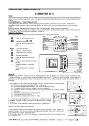
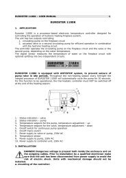
1.IntroductionAs part of the wide range of Honeywell´s product portfolio for wireless communication products we provide heatingsolutions for individual zoning control. This application manual explains examples for heating solutions, particularly forradiator, underfloor and electrical heating control.1.1Wireless communicationThe peripherals communicate with the evotouch controller based on our proven RF wireless technology 868 MHZ.The products include a transceiver which allows bi-directional (two-way) communication or uni-directional (one-way)communication with the evotouch controller.DT92 HCW82 HCF82 HB85evotouchHCE80 (R)HCC80 (R)BDR91HC60NGHM80HR80<strong>Application</strong> <strong>Manual</strong> 3
1.2Product overviewPicture Product OS number Descriptionevotouch controllerModern designed multizoning controller with touchscreen display for up to 8 zones. With individual timeprogram for each zone, guided programming, text-baseduser guide.Underfloor heatingcontrollerUnderfloor heatingcontrollerHCE80(R)HCC80(R)Underfloor heating controller for up to 5 zones. Pumpcontrol, analogue output for boiler feedback MCR200,MCR40, EXCEL controllers. External antenna required.Optional wireless boiler feedback via relay BDR91. Eachoutput can drive up to 3 thermal actuators. The HCE80Rhas the same configuration, but instead of an analogueoutput it has an integrated boiler relay.Underfloor heating controller for up to 5 zones. Pumpcontrol, analogue output for boiler feedback MCR200,MCR40, EXCEL controllers. Antenna integrated.Optional wireless boiler feedback via relay BDR91. Eachoutput can drive up to 3 thermal actuators, transceiver868 MHz. The HCC80R has the same configuration, butinstead an analogue output it has an integrated boilerrelay.External antenna HRA80 External active antenna for HCE80(R). Up to3 controllers can be connected to one antenna,transceiver 868 MHz.OPENTHERM-Bridge R8810A1018 OPENTHERM-Bridge interface for boiler control (heaton demand), transceiver 868 MHz.Extension module HCS80 3 zones upgrade for HCE80(R) / HCC80(R) from 5 to8 zones.Room sensor HCF82 Room unit with integrated temperature sensor, batterypowered(2x1,5V AA LR6), transmitter 868 MHz.Room sensor /setpoint adjustmentHCW82 Room unit with integrated temperature sensor /setpoint adjustment +/– 12 °C. Window contact, batterypowered(2x1,5V AA LR6) or external power supply,transmitter 868 MHz.Digital room unit DT92 Digital room unit with integrated temperature sensorand setpoint adjustment 8 to 30 °C, battery-powered(2x1,5 V AA LR6), transceiver 868 MHz.Mixing valve controller HM80Mixing valve controller for 3-position mixing valve. Withpump control and flow temperature sensor connection.Adjustable parameters: valve run time, pump runningtime, min./max. flow temperature, manual overridebuttons to open/close valve, receiver 868 MHz.4 evotouch
Picture Product OS number DescriptionRadiator controller HR80 Radiator controller with energy-saving features,e.g. window function, manual setpoint override, displayoperating status and battery exchange. Fits valvesof brands Honeywell Braukmann, MNG, Heimeier,Junkers, Oventrop beginning from 03/1998. Adaptorsfor Danfoss, Herz, Vaillant, Oventrop available. Batterypowered(2x1,5 V AA LR6), transceiver 868 MHz.Relay module 5 A BDR91 Relay module with change over contact 5 A,transceiver 868 MHz.Relay module 8 AHC60NG/R6660DRelay module with change over contact 8 A,receiver 868 MHz.Outdoor sensor HB85 Module with integrated temperature sensor formeasuring the outside temperature. Battery-powered(2x1,5 V AA LR6), transmitter 868 MHz.AccessoriesThermal actuator MT4-230 NG Thermal actuator normally closed 230 V ACThermal actuator MT4-230 NO Thermal actuator normally open 230 V AC<strong>Application</strong> <strong>Manual</strong> 5
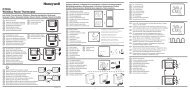
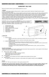
2.<strong>Application</strong> examples2.1Single zone thermostat with boiler controlHB85Zone 1BDR91evotouchBoiler room Zone 1Notes• The internal room sensor of the evotouch controller must be activated• BDR91 relay module or OPENTHERM-Bridge can be used6 evotouch
<strong>Application</strong> descriptionThis application shows 1 zone boiler control where the evotouch controller controls the boiler directly depending on heatdemand via the BDR91 relay module (switching ON/OFF).The internal room sensor of the evotouch controller is used in order to measure the room temperature.Option• Outdoor sensorThe HB85 outdoor sensor measures the outside temperature. It must be installed if data is required.Steps to doffActivate the internal room sensor of the evotouch controller. See section 4.2ffBind BDR91 relay module / OPENTHERM-Bridge to the evotouch controller. See section 4.4ff Check RF communication.<strong>Application</strong> <strong>Manual</strong> 7
2.2Two zone system with zone valvesDT92Zone 2 Zone 1BDR91Zone 2BDR91evotouchBoiler room Zone 1Notes• The internal room sensor of the evotouch controller must be activated for zone 1• Instead of DT92 the HCW82 / HCF82 room units can be used8 evotouch
<strong>Application</strong> descriptionFor zone 1, the internal room sensor of the evotouch controller is used.Zone 2 requires the DT92 room unit for the room temperature measurement and local remote setpoint adjustment.The setpoints can be altered directly on the evotouch controller by manual override, time program, lifestyle actions andDT92 as well. The same actual room temperature setpoint will be displayed on the evotouch controller and DT92.In total, 8 zones can be controlled individually.Options• Heat demandThe evotouch controller calculates the heat demand and communicates it to the boiler relay BDR91 / HC60NG orOPENTHERM-Bridge which controls the boiler.• Outdoor sensorThe HB85 outdoor sensor measures the outside temperature. It must be installed if data is required.Steps to doffActivate the internal room sensor of the evotouch controller for zone 1. See section 4.2ffBind the evotouch controller to the DT92 as room/setpoint sensor to zone 2. See section 4.8ffBind the evotouch controller to the BDR91 / HC60NG relay module to zone 1 and zone 2. See section 4.4ffOptional: Bind the evotouch controller to the BDR91 relay module / OPENTHERM-Bridgefor boiler control. See section 4.5ffOptional: Bind the evotouch controller to the HB85 sensor for outdoor temperature. See section 4.10ff Check RF communication for each sensor and actuator individually.<strong>Application</strong> <strong>Manual</strong> 9
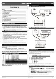
2.3Multizone system with radiatorsExample: 6 zones, up to 8 zones are possibleHR80HR80HR80Zone 4 Zone 5 Zone 6 ... 8HR80HR80Zone 2BDR91evotouchZone 3HR80Boiler room Zone 1Notes• The internal room sensor of the evotouch controller must be activated for zone 1• Zone 1: HR80 internal room sensor not used• Optional boiler feedback: BDR91 relay module or OPENTHERM-Bridge10 evotouch
<strong>Application</strong> descriptionThe integrated room sensor of the HR80 is used to measure the room temperature and compare it with the received roomsetpoint from the evotouch controller. Depending on the temperature deviation, the radiator valve is controlled to achievethe target room temperature setpoint. The integrated room sensor of the evotouch controller can be activated as well foronly one zone.Several HR80s can be bound to one zone. There are no limitations, only the RF signal’s range is limited to the distanceof max. 30 m.In total, 8 zones can be controlled individually.Options• Heat demandThe evotouch controller calculates the heat demand and communicates it to the boiler relay BDR91 / HC60NG orOPENTHERM-Bridge which control the boiler.• Outdoor sensorThe HB85 outdoor sensor measures the outside temperature. It must be installed if data is required.Steps to doffActivate the internal room sensor of the evotouch controller for zone 1. See section 4.2ffBind the evotouch controller to each HR80’s integrated room sensor individuallyfor each zone 2 – 6. See section 4.3.1ffBind the evotouch controller to each HR80’s actuator individually for each zone 1 – 6. See section 4.3.2ffOptional: Bind the evotouch controller to the BDR91 relay module / OPENTHERM-Bridgefor boiler feedback. See section 4.5ffOptional: Bind the evotouch controller to the HB85 sensor for outdoor temperature. See section 4.10ff Check RF communication for each sensor and actuator individually.<strong>Application</strong> <strong>Manual</strong> 11
2.4Multizone system with radiators and remote sensorExample: 6 zones, up to 8 zones are possibleHR80HR80HR80Zone 4 Zone 5 Zone 6 ... 8DT92HR80HR80Zone 2BDR91HR80evotouchZone 3Boiler room Zone 1Notes• The internal room sensor of the evotouch controller must be activated for zone 1• Instead of DT92 the HCW82 / HCF82 room units can be used• Zones 1 and 2: HR80 internal room sensor not used• Optional heat demand: BDR91 relay module or OPENTHERM-Bridge12 evotouch
<strong>Application</strong> descriptionThis application shows when the HR80 integrated room sensor should be used or, alternatively, the DT92 remote sensor.The precise room temperature measurement requires air flow through the HR80 room sensor which is not always possible,particularly if the radiators are faced with e.g. wood, which causes an imprecise temperature measurement (see examplesin zone 1 and zone 2). Therefore, in zone 1 the internal sensor from the evotouch controller is used to measure the roomtemperature. For zone 2 the DT92 room unit is used which also allows to change the room temperature setpoint remotely(manual override).The room temperature from zones 3 – 6 is measured directly by each HR80.Up to 8 zones can be controlled individually with the radiator controller HR80 in combination with remote units DT92,HCW82 or HCF82.Options• Heat demandThe evotouch controller calculates the heat demand and communicates it to the boiler relay BDR91 / HC60NG orOPENTHERM-Bridge which control the boiler.• Outdoor sensorThe HB85 outdoor sensor measures the outside temperature. It must be installed if data is required.Steps to doffActivate the internal room sensor of the evotouch controller for zone 1. See section 4.2ffBind the evotouch controller to each HR80’s integrated room sensor individuallyfor each zone 3 – 6. See section 4.3.1ffBind the evotouch controller to each HR80’s actuator individually for each zone 1 – 6. See section 4.3.2ffBind the evotouch controller to the DT92 room unit for zone 2. See section 4.8ffOptional: Bind the evotouch controller to the BDR91 relay module / OPENTHERM-Bridgefor boiler feedback. See section 4.5ffOptional: Bind the evotouch controller to the HB85 sensor for outdoor temperature. See section 4.10ff Check RF communication for each sensor and actuator individually.<strong>Application</strong> <strong>Manual</strong> 13
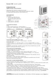
2.5Multizone system with underfloor heating individual room thermostatExample: 6 zones, up to 8 zones are possibleDT92DT92DT92DT92Zone 4 Zone 5 Zone 6 ... 8DT92Zone 2HCE80(R) /HCC80(R)BDR91(R)evotouchZone 3Boiler room Zone 1Notes• The internal room sensor of the evotouch controller must be activated for zone 1• Instead of DT92 the HCW82 / HCF82 room units can be used• Optional boiler feedback: BDR91 relay module or OPENTHERM-Bridge14 evotouch
<strong>Application</strong> descriptionThe underfloor heating controller controls 6 zones individually. For zone 1, the evotouch internal room sensor is used.All other zones (2 – 6) require their own room unit DT92 in order to measure the room temperature and adjust the roomtemperature setpoint remotely.The DT92 communicates directly with the evotouch controller in order to exchange the room temperature setpoints thatcan be altered by manual override, time program or lifestyle actions at the evotouch controller.The underfloor heating controller communicates only with the evotouch controller directly and receives the roomtemperature and room temperature setpoint for each zone individually.In total, 8 zones can be controlled individually.Options• Heat demandThe evotouch controller calculates the heat demand and communicates it to the boiler relay BDR91 / HC60NG orOPENTHERM-Bridge which control the boiler.• Outdoor sensorThe HB85 outdoor sensor measures the outside temperature. It must be installed if data is required.Steps to doffActivate the internal room sensor of the evotouch controller for zone 1. See section 4.2ffBind the evotouch controller to each room unit DT92 individually for zones 2 – 6. See section 4.8ffBind the sensor information from the evotouch controller to the underfloor heating controllerindividually for each zone 1 – 6. See section 4.7.1ffBind the setpoint information from the evotouch controller to the underfloor heating controllerindividually for each zone 1 – 6. See section 4.7.2ffOptional: Bind the evotouch controller to the BDR91 / OPENTHERM-Bridge relay modulefor boiler feedback. See section 4.5ffOptional: Bind the evotouch controller to the HB85 sensor for outdoor temperature. See section 4.10ff Check RF communication for each sensor and actuator individually.<strong>Application</strong> <strong>Manual</strong> 15
2.6Multizone system with underfloor heating individual room sensorExample: 6 zones, up to 8 zones are possibleHCF82HCF82HCF82HCF82Zone 4 Zone 5 Zone 6 ... 8HCF82Zone 2HCE80(R) /HCC80(R)BDR91evotouchZone 3Boiler room Zone 1Notes• The internal room sensor of the evotouch controller must be activated for zone 1• Optional heat demand: BDR91 relay module or OPENTHERM-Bridge16 evotouch
<strong>Application</strong> descriptionThe HCE80(R) / HCC80(R) underfloor heating controllers individually control up to 8 zones. For zone 1, the internal roomsensor from the evotouch controller is used. All other zones (2 – 6) require their own HCF82 room sensor to measurethe room temperature.The HCF82 directly communicates with the evotouch controller in order to send the room temperature. The roomtemperature setpoints change according to the time program. The manual setpoint override is only possible with theevotouch controller.The underfloor heating controllers HCE80(R) / HCC80(R) communicate directly only with the evotouch controller andreceive the room temperature and room temperature setpoint for each zone individually.In total, 8 zones can be controlled individually.OptionsHeat demandThe evotouch controller calculates the heat demand and communicates it to the boiler relay BDR91 / HC60NG orOPENTHERM-Bridge which controls the boiler.Outdoor sensorThe HB85 outdoor sensor measures the outside temperature. It must be installed if data is required.Steps to doffActivate the internal room sensor of the evotouch controller for zone 1. See section 4.2ffBind the evotouch controller to the HCF82 room sensor individually for each zone 2 – 6. See section 4.9ffBind the sensor information from the evotouch controller to the underfloor heating controllerindividually for each zone 1 – 6. See section 4.7.1ffBind the setpoint information from the evotouch controller to the underfloor heating controllerindividually for each zone 1 – 6 See section 4.7.2ffOptional: Bind the evotouch controller to the BDR91 / HC60NG relay modulefor boiler feedback. See section 4.5ffOptional: Bind the evotouch controller to the HB85 sensor for outdoor temperature. See section 4.10ff Check RF communication for each sensor and actuator individually.<strong>Application</strong> <strong>Manual</strong> 17
2.7Multizone system with radiators and underfloor heatingExample: 6 zones, up to 8 zones are possibleHR80HR80HR80Zone 4 Zone 5 Zone 6 ... 8DT92DT92HR80Zone 2HCE80(R) /HCC80(R)BDR91evotouchZone 3Boiler room Zone 1Notes• The internal room sensor of the evotouch controller must be activated for zone 1• Instead of DT92 the HCW82 / HCF82 room units can be used• Zone 3: HR80 internal room sensor not used• Optional boiler feedback: BDR91 relay module or OPENTHERM-BridgeFor that mixed application you can setup the configuration as following:ff Select menu GUIDED CONFIG and configure the 4 zones for radiator controlff Select menu ZONING CONFIG and add the 2 zones for underfloor heating control ADD ZONEAlternative go to the expert menu:ff Select menu ZONING CONFIG and add the 4 zones for Radiator control ADD ZONEff Select menu ZONING CONFIG and add the 2 zones for underfloor heating control ADD ZONEThe Binding process in the EXPERT MENÜ is the same as for GUIDED CONFIGURATION however the RF test must bechoosen in the MENU SYSTM CONFIGURATION BINDING AND RF TEST individual for each zone.18 evotouch
<strong>Application</strong> descriptionThis is a typical application which shows the combination of underfloor heating and radiator control. Zones 1 and 2 arecontrolled by the underfloor heating controller HCE80 and zones 3 – 6 by radiator controllers HR80.Zone 1 uses the internal room sensor from the evotouch controller, while zones 2 and 3 use the DT92 room unit tomeasure the room temperature and remote setpoint adjustment.Zones 4, 5 and 6 individually use their HR80’s integrated room sensor.All peripheral devices communicate directly with the evotouch controller. The room temperature setpoints can be alteredmanually or by e.g. time program or lifestyle actions with the evotouch controller.This mixed application can be used for up to 8 zones.Options• Heat demandThe evotouch controller calculates the heat demand and communicates it to the BDR91 / HC60NG boiler relay orOPENTHERM-Bridge which control the boiler.• Outdoor sensorThe HB85 outdoor sensor measures the outside temperature. It must be installed if data is required.Steps to doffActivate internal room sensor of the evotouch controller for zone 1. See section 4.2ffBind the evotouch controller to the DT92 room unit individually for zones 2 and 3. See section 4.8ffBind the evotouch controller to each HR80’s integrated room sensor individuallyfor each zones 4 – 6. See section 4.3.1ffBind the evotouch controller to each HR80’s actuator individually for zones 3 – 6. See section 4.3.2ffBind the sensor information from the evotouch controller to the underfloor heating controllerindividually for each zone 1 – 6. See section 4.7.1ffBind the setpoint information from the evotouch controller to the underfloor heating controllerindividually for each zone 1 and 2. See section 4.7.2ffOptional: Bind the evotouch controller to the BDR91 / HC60NG relay module forboiler feedback. See section 4.5ffOptional: Bind the evotouch controller to the HB85 sensor for outdoor temperature. See section 4.10ff Check RF communication for each sensor and actuator individually.<strong>Application</strong> <strong>Manual</strong> 19
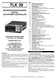
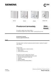
2.8Multizone system with mixing valve and radiatorsExample: 6 zones, up to 8 zones are possibleHR80HR80HR80Zone 4 / MK1 Zone 5 / MK1 Zone 6 / MK1 ... 8HR80HR80Zone 2 / MK1Zone 3 / MK1BDR91HM80evotouchMMK2Boiler roomZone 1 / MK2Notes• The internal room sensor of the evotouch controller must be activated for zone 1• HM80 mixing valve controller: mixing valve run time / pump after run time / min/max flow temperature• Optional heat demand: BDR91 relay module or OPENTHERM-BridgeFor that mixed application you can setup the configuration as following:ff Select menu GUIDED CONFIG and configure the 5 zones for radiator controlff Select menu ZONING CONFIG and add the 1 zone for underfloor heating control ADD ZONEAlternative go to the expert menu:ff Select menu ZONING CONFIG and add the 5 zones for Radiator control ADD ZONEff Select menu ZONING CONFIG and add the 1 zone for underfloor heating control ADD ZONEThe Binding process in the EXPERT MENÜ is the same as for GUIDED CONFIGURATION however the RF test must bechoosen in the MENU SYSTM CONFIGURATION BINDING AND RF TEST individual for each zone.20 evotouch
<strong>Application</strong> descriptionThis application shows two heating circuits: one for radiator MK1 and one for underfloor heating MK2. The HR80 radiatorcontrollers belong to the heating circuit MK1 (zones 2 – 6) which use their own integrated room sensor.Zone 1 (underfloor heating MK2) is controlled by the mixing valve controller HM80 and the evotouch controller’s internalroom sensor is used to measure the room temperature. The evotouch controller also sends the room temperaturesetpoints and parameters to the HM80.For optimal operation, the parameters can be set at the mixing valve for each individual zone’s HM80.The evotouch controller can control up to 8 zones with HM80. However, each zone requires its own HM80 and sensordevice, e.g. HCF82, HCW82 or DT92.Options• Heat demandThe evotouch controller calculates the heat demand and communicates it to the BDR91 / HC60NG boiler relay orOPENTHERM-Bridge which control the boiler.• Outdoor sensorThe HB85 outdoor sensor measures the outside temperature. It must be installed if data is required.Steps to doffActivate internal room sensor of the the evotouch controller for zone 1. See section 4.2ffBind the evotouch controller to each HR80’s integrated room sensor individuallyfor each zone 2 – 6. See section 4.3.1ffBind the evotouch controller to each HR80’s actuator individually for each zone 2 – 6. See section 4.3.2ffBind the evotouch controller to the mixing valve controller HM80 for zone 1. See section 4.6ffOptional: Bind the evotouch controller to the BDR91 / HC60NG relay modulefor boiler feedback. See section 4.7ffOptional: Bind the evotouch controller to the HB85 sensor for outdoor temperature. See section 4.10ff Check RF communication for each sensor and actuator individually.<strong>Application</strong> <strong>Manual</strong> 21
2.9Multizone boiler control with up to 4 controllersevotouch 4evotouch 3evotouch 1BDR91evotouch 2Boiler roomNote• Instead of the BDR91 relay module the OPENTHERM-Bridge can be used<strong>Application</strong> descriptionThe boiler relay or OPENTHERM-Bridge can receive the heat demand signal from up to 4 evotouch controllers in orderto control the boiler based on the required heat demand.Each controller calculates the maximum heat demand and will send this information to the boiler relay.Each controller must be bound to the boiler relay.22 evotouch
3.<strong>Application</strong> settingsParameters can be set for optimum operation and control performance of the system in the specific application.Underfloor heatingParameterSettings / rangeMin/max temperature setpoint 5 ... 35 °CRadiator heatingParameterSettings / rangeOptimisationEnabled / disabledWindow functionEnabled / disabledMin/max temperature setpoint 5 ... 35 °CLocal overrideEnabled / disabledMixing valveParameter Range Default settingMixing valve run time 0 ... 240 s 150 sPump run time 0 ... 99 min 15 minMinimum flow temperature 0 ... 50 °C 15 °CMaximum flow temperature 0 ... 99 °C 55 °CZone valvesParameterSettings / rangeFail saveEnabled / disabledMin/max temperature setpoint 5 ... 35 °C<strong>Application</strong> <strong>Manual</strong> 23
4.Generic BindingNew components of the zoning system, which have capabilities to communicate wireless based on 868 MHz technology,have to be integrated into the system before they can be taken into operation. This process is called BINDINGThe binding procedure in the evotouch controller is guided by help screens which lead the installer through theprocedure.Only the peripheral devices like actuators, sensors etc. have to be set into the individual bind mode by pressing e.g. theBIND button.After BINDING, the peripherals are able to communicate with the evotouch controller to receive or transmit data. Inaddition, the RF communication can be checked and the signal strength is indicated and displayed.As an example the following procedures are described for a living room.4.1Configuration modesThe zone configuration of the evotouch controller basicly can be done by the GUIDED Configuration and EXPERTConfiguration.Particularly if you have mixed applications e.g. 4 zones radiator control and 2 zones underfloor heating control theconfiguration mode which should be applied is described in the specific application Multizone system with radiatorsand underfloor heating and Multizone system with mixing valve and radiators.4.1.1GUIDED configurationffPress and hold the MENU button until the next screenappears.ff Press the YES button.24 evotouch
ffPress the button GUIDED CONFIGffPress the YES button.ff Depending on your needs, select a button to press.ff Follow the next guided screens<strong>Application</strong> <strong>Manual</strong> 25
4.1.2EXPERT configurationffPress the button MENU.The next screen appears.ffPress the button ZONING MENU.ffPress the button ZONING CONFIGffPress the button “ Press for 5 seconds to enter” andhold the button for 5 seconds until the next screenappears..26 evotouch
ffffDepending on your needs, select a button to press.Follow the next screensNotesIf you have mixed applications example 5 zones radiator control and 3 zones underfloor heating control you can setup theconfiguration as following:ffSelect menu GUIDED CONFIG and configure the 5 zones for radiator controlff Select menu ZONING CONFIG and add the 3 zones for underfloor heating control ADD ZONEAlternative go to the expert menu:ff Select menu ZONING CONFIG and add the 5 zones for Radiator control ADD ZONEff Select menu ZONING CONFIG and add the 3 zones for underfloor heating control ADD ZONEThe Binding process in the EXPERT MENÜ is the same as for GUIDED CONFIGURATION however the RF test must bechoosen in the MENU SYSTM CONFIGURATION “BINDING AND RF TEST” individual for each zone.4.2Sensor bindingTo each zone a room sensor must be assigned. This can be an internal sensor or an external remote sensor.Before entering the binding sequence, the following choice is to be made:• Selecting INTERNAL, the room sensor of the evotouchcontroller will be used. You don’t need to bind thissensor.• Selecting EXTERNAL, an external room sensor, e.g.DT92, will be used. This sensor must be bound to theevotouch controller.<strong>Application</strong> <strong>Manual</strong> 27
4.3Binding the evotouch controller to the HR80 radiator controller4.3.1Binding the HR80 integrated room sensorffFollow the guided or expert configuration until thefollowing screen appears.ffffPosition the evotouch controller close to the HR80which is connected to the valve.Press the bind button (1) on the HR80.After successful binding the following screenappears.iNEXT leads you to the binding of the actuator.28 evotouch
4.3.2Binding the HR80 actuator(s)ffFollow the guided or expert configuration until thefollowing screen appears.ffffPosition the evotouch controller as close as possibleto the HR80 actuator(s).Consecutively press the bind buttons (1) on all theHR80 radiator controllers of the zone.ffPress the BIND button on the evotouch controller tosend the signal.The symbol flashes and the software version numberis displayed for 30 seconds.During the binding procedure, the symbol is showncontinuously in the display of the HR80 radiatorcontroller. The display shows: sync .The HR80 radiator controller is receiving data fromthe evotouch controller. This process can take up to4 minutes.iThe binding procedure mode remains active at theHR80 radiator controller for a maximum of 4 minutes.i NEXT leads you to the RF communication check.<strong>Application</strong> <strong>Manual</strong> 29
4.3.3Checking RF communication with the HR80 radiator controllerThe evotouch controller will send and receive test signals to and from the assigned HR80 to test the signal strength.evotouch controller receiving test messages from the HR80ff Separate HR80 operating unit from coupling module(see instructions HR80).ffTurn the adjustment dial until on (open) appears onthe display.ff Turn the adjustment dial two full rotations (720°)further.TesT is displayed and the HR80 transmits the testmessage to the evotouch controller.iThe signal strength can be EXCELLENT, GOOD, POORor not receivedHR80 receiving test signal from the evotouch controllerffWhile TesT is displayed, press the bind button (1) onthe HR80.The HR80 radiator controller is ready to receive thetest message from the evotouch controller.The first two digits in the display indicate the numberof received test messages, and the right-hand digitindicates the field strength1 = sufficient field strength5 = very good field strengthDeactivating the RF communication checkfforfforffPress the bind button (1) on the HR80 for 5 seconds.Wait 5 minutes.Remove and re-insert the batteries of the HR80.Completing configurationff Press the NEXT button and in the following screen press the DONE button.Configuration of the HR80 radiator controller is completed.30 evotouch
4.4Binding the evotouch controller to the BDR91 / HC60NG / R6660D relaymodule4.4.1Binding procedureffFollow the guided or expert configuration until thefollowing screen appears.ff Press and hold the bind button of the BDR91 / HC60NG/ R6660D relay module for 5 sec to activate the bindmode.The red LED flashing at 0.5 s ON / 0.5 s OFF confirmsthat the bind mode has been activated.BDR91HC60NG / R6660DiAfter the power up of the BDR91 relay module the redLED will start to flash at 0.1 s ON / 0.9 s OFF. If this isnot the case, set the BDR91 into the reset mode, seeinstructions BDR91 / HC60NG.ffffPosition the evotouch controller as close as possibleto the BDR91 / HC60NG / R6660D relay module(s).Press the BIND button on the evotouch controller tosend the bind signal to the BDR91 / HC60NG / R6660Drelay module(s)The red LED of the BDR91 / HC60NG / R6660D isswitched OFF to confirm a successful binding.i Binding is terminated automatically after 5 minutes.<strong>Application</strong> <strong>Manual</strong> 31
4.4.2Checking RF communicationBDR91The evotouch controller sends test signals to and from theassigned relay module BDR91 in order to test the signalstrength.iThe signal strength can be EXCELLENT, GOOD, POORor not receivedHC60NG / R6660DThe evotouch controller sends test signals to the assignedrelay module HC60NG / R6660D in order to test the signalstrength.When HC60NG / R6660D receives the test signal, the fieldstrength is indicated by flashing of the red LED.1 pulse = sufficient5 pulses = strongDeactivating the RF communication checkffPress the NEXT button.Completing configurationff In the following screen press the DONE button.Configuration of the relay module is completed.32 evotouch
4.5iBinding the evotouch controller to the OPENTHERM-Bridge boilerfeedbackThe following modules can be used for boiler feedback as well: BDR91, HC60NG, R6660D.For the BIND buttons and checking RF communication of these modules see section 4.4.4.5.1Binding procedureffFollow the guided or expert configuration until thefollowing screen appears.Press and hold the bind button (1) of the OPENTHERM-Bridge for 5 seconds to activate the bind mode.ffffPress the BIND button on the the evotouch controllerto send the bind signal to the OPENTHERM-Bridge.The red LED of the OPENTHERM-Bridge is switchedoff to confirm a successful binding.i Binding is terminated automatically after 5 minutes.<strong>Application</strong> <strong>Manual</strong> 33
4.5.2Checking RF communicationThe evotouch controller sends test signals to the assignedOPENTHERM-Bridge in order to test the signal strength.When OPENTHERM-Bridge receives the test signal, thefield strength is indicated by flashing of the red LED.1 pulse = sufficient5 pulses = strongDeactivating the RF communication checkffPress the NEXT button.Completing configurationff In the following screen press the DONE button.Configuration of the OPENTHERM-Bridge boiler feedback is completed.34 evotouch
4.6Binding the evotouch controller to the HM80 mixing valve controller4.6.1Binding procedureffFollow the guided or expert configuration until thefollowing screen appears.ffPress both buttons (1) and (2) at the HM80 for approx.4 seconds until the LED (3) flashes regularly.321ffffPosition the evotouch controller as close as possibleto the HM80 mixing valve controller.Press the BIND button on the evotouch controllerto send the bind signal to the HM80 mixing valvecontroller.The LED (3) of the HM80 is switched OFF to confirm asuccessful binding.i Binding is terminated automatically after 3 minutes.<strong>Application</strong> <strong>Manual</strong> 35
4.6.2Checking RF communicationThe evotouch controller sends test signals to the assignedHM80 in order to test the signal strength.When HM80 receives the test signal, the field strength isindicated by flashing of the red LED (4).1 pulse = sufficient5 pulses = strongNoteSensor information relates to the sensor in the zonecontrolled by the HM80.Deactivating the RF communication checkffPress the NEXT button.Completing configurationff In the following screen press the DONE button.Configuration of the HM80 mixing valve is completed.36 evotouch
4.7Binding the evotouch controller to the HCE80(R) / HCC80(R) underfloorheating controlleri For zones 2 – 6 an external room sensor (DT92 / HCW82 / HCF82) must be bound to the evotouch controller.4.7.1Binding room sensorffFollow the guided or expert configuration until thefollowing screen appears.ffPress and hold the installation button (1) at theunderfloor heating controller for approx. 2 seconds.The LED of zone 1 flashes red.123ffffffPosition the evotouch controller as close as possibleto the underfloor heating controller.Press the BIND button on the evotouch controllerto send the bind signal to the underfloor heatingcontroller.The LED of the selected one lights continuously red.Press the BACK button on the evotouch controller toproceed with the binding of the room setpoint.<strong>Application</strong> <strong>Manual</strong> 37
4.7.2Binding room setpointffFollow the guided or expert configuration until thefollowing screen appears.ffPress and hold the installation button (1) at the underfloorheating controller again for approx. 2 seconds.The LED of zone 1 (2) flashes green.123ffffPosition the evotouch controller as close as possibleto the underfloor heating controller.Press the BIND button on the evotouch controllerto send the bind signal to the underfloor heatingcontroller.The LED of zone 1 (2) lights continuously green.Binding of further zonesiIn order to assign further zones press the installation button again until the LED of the desired zone flashes red andthen repeat the binding procedure.38 evotouch
4.7.3Checking RF communicationThe evotouch controller sends test signals to the assignedunderfloor heating controller in order to test the signalstrength.When the underfloor heating controller receives the testsignal, the field strength is indicated by flashing of thegreen zone LED (2).1 pulse = sufficient5 pulses = strongNoteSensor information relates to the sensor in the zonecontrolled by the HCE80.Deactivating the RF communication checkffPress the NEXT button.Completing configurationff In the following screen press the DONE button.Configuration of the HCE80(R) / HCC80(R) underfloor heating controller is completed.<strong>Application</strong> <strong>Manual</strong> 39
4.8Binding the evotouch controller to the DT92 room adjuster/sensor4.8.1Binding procedureffffFollow the guided or expert configuration until thefollowing screen appears.Position the evotouch controller as close as possibleto the DT92.ff Press and hold both arrows up and down until thedisplay changes.ff Press button (1).Binding takes place automatically.Press button (1) approx. 5 sec. when the display onDT92 does not appear as pictures shows.iiThe binding mode remains active for max. 10 minutesafter the last button was pressed.140 evotouch
4.8.2Checking RF communicationff Select Menu BINDING AND RF TEST.The DT92 controller sends test signals to the evotouchcontroller in order to test the signal strength.The device is now in the test mode and sends test signalsto the evotouch controller.iThe signal strength can be EXCELLENT, GOOD, POOR or not received.Deactivating the RF communication checkffRemove and re-insert the batteries of the DT92.Completing configurationff Press the DONE button.Configuration of the DT92 room adjuster/sensor is completed.<strong>Application</strong> <strong>Manual</strong> 41
4.9Binding the evotouch controller to the HCW82 room adjuster/sensor or tothe HCF82 room sensor4.9.1Binding procedureffffFollow the guided or expert configuration until thefollowing screen appears.Position the evotouch controller as close as possibleto the HCW82 / HCF82.ffPress and hold the bind button (1) on the HCF82 /HCW82 for approx. 1 second.Binding takes place automatically.1i Binding is terminated automatically after 5 minutes.242 evotouch
4.9.2Checking RF communicationff Select Menu BINDING AND RF TEST.HCW82 / HCF82 send test signals to the evotouchcontroller in order to test the signal strength.ff Press and hold the bind button of the HCW82 / HCF82for at least 30 seconds until the red LED extinguishes.The device is now in test mode and sends a test signalevery 5 seconds. The LED (2) flashes briefly at everytest signal.The field strength is indicated on the evotouchcontroller.iThe signal strength can be EXCELLENT, GOOD, POOR or not received<strong>Application</strong> <strong>Manual</strong> 43
Deactivating the RF communication checkff Remove and re-insert the batteries of the DT92.orff Disconnect the power supply.orff Press the bind button.Completing configurationff Press the DONE button.Configuration of the HCW82 / HCF82 is completed.4.10Binding the evotouch controller to the HB85 temperature sensor4.10.1iBinding procedureTo check whether the radio connection is ready for later operation, during binding the temperature sensor moduleshould remain as near as possible to the mounting site.ffFollow the guided or expert configuration until thefollowing screen appears.ffPress the bind button (1) on the HB85.Binding takes place automatically.i Binding is terminated automatically after 4 minutes.iAfter successful binding, the HB85 transmits themeasured data to the evotouch controller at intervalsof approx. 10 minutes.44 evotouch
4.10.2Checking RF communicationHB85 sends test signals to the evotouch controller in orderto test the signal strength.ffPress the bind button of the HB85 briefly.For approx. 10 minutes, HB85 transmits a test messageto the evotouch controller every 5 seconds.The field strength is indicated on the evotouchcontroller.iThe signal strength can be EXCELLENT, GOOD,POOR or not receivedCompleting configurationff Press the DONE button.Configuration of the HB85 temperature sensor is completed.<strong>Application</strong> <strong>Manual</strong> 45
46 evotouch
<strong>Application</strong> <strong>Manual</strong> 47
Honeywell Control System Ltd.Arlington Business Park,Bracknell, BerkshireRG12 1EBTechnical Help Desk: 08457 678999www.honeywelluk.comDoku-Nr. 50042748-001© 2009 Honeywell International Inc.Manufactured for and on behalf of the Environmental and Combustion Controls Division of Honeywell Technologies Sàrl, Rolle, Z.A. La Pièce 16, Switzerland by its Authorized Representative:
• evotouch controller for individual zoning control up to8 zones.• Intuitive local language operating menu structure anduser guided programming.• Large touch screen display with easy to read zone andtemperature information.• Modern design with exchangeable front covers.• Simple binding operation to reduce installation timeand costs.• Applicable for radiators, underfloor heating andmixing valve control in home or office environmentwith optional control for boiler, heat pump.• Proven wireless communication (no disruption ofinterior decor, ideally suitable for existing homes).• Prepared for new functionalities via PC link.• Optimized heating control, can lower the heatingcosts. The Honeywell evotouch controller is a modern designedprogrammable multi zone controller.evotouch is providing a very explanatory touch-screen displayallows for intuitive, easy and self explanation operation byfinger tip or by touch-pen.It’s available both as a table or wall device in polished black,brushed metal and gloss whiteIt will control your heating system efficiently by providingmaximum comfort and energy saving.A total of up to eight individual temperature zones and timeprograms can be set up.The evotouch controller is part of the individual room controlsystem in the form of evohome.The evohome system enables control of underfloor heating,radiators, zone valves, boiler feedback and mixer circuits.evotouch is like the other peripherals of the evohome systemequipped with our proven wireless RF (Radio Frequency)technology based on 868MHZ.Once everything is set up, the end consumer can use theevotouch controller to easily regulate his respective comfortrequirements.50042749-001
evohome Electrical voltage supply: 4VDC ± 0,2V, max. 2,6WBattery: Frequency:2x rechargeable batteryAA 1.2V NiMHReceiver class: RC class 2Recommended 2000m-2400mAhISM (868,0 – 870,0) MHz,1% duty cycle, TransceiverRF communication range: 30 m in a residential buildingenvironmentRF communication:Technology: Touch screen:short, high rate transmission tominimize air time and avoidcollisionsLCD gray scale graphic backlitdisplay , 16 levels480 x 272 pixel96 x 56 mm display area # Internal room temperatureSensor:# Dimensions (WxHxD):Material:(NTC) operating range0°C to 40°C139 x 101 x 21mm (WxDxH)PC141RIP class: IP 30 Mounting:table top stand ! USB connection: DeviceHardware upgrade: sub module " # $ Operating temperature: 0 … +40 ºCShipping and Storage: -20 … +50 ºCTemperature:Humidity:max. 10 … 90 % relativehumidity non condensing Meeting the followingStandards:CE approvedRoHS-complaint50042749-001 2
evohomeInstallation instructions3 50042749-001
evohomeInstallation instructions50042749-001 4
evohome<strong>Application</strong> ExamplesSingle zone thermostat with boiler control<strong>Application</strong> descriptionThis application shows 1 zone boiler control where theevotouch controller controls the boiler directly dependingon the heat demand via the BDR91 relay module(switching ON/OFF).The internal room sensor of the evotouch controller isused to measure the room temperature.Multizone system with radiators and remote sensors<strong>Application</strong> descriptionRadiator application with used integratedroom sensor of HR80 or external remotesensor DT92. Because in some cases theradiators are faced with e.g. wood whichcauses an imprecise temperaturemeasurement see example zoe1 and zone2.In zone1 the internal room sensor of theevotouch controller is used to measure theroom temperature. For zone 2 the DT92room unit is used also for remoteadjustment.The room temperature from zones 3-6 ismeasured directly by each HR80.Up to 8 zones can be controlled individuallywith the radiator controller HR80 incombination with room units DT92, HCW82or HCF82.5 50042749-001
evohomeMultizone system with underfloor heating individual room thermostat<strong>Application</strong> descriptionThe underfoor heating controller controls 6zones individually. For zone 1 the internalroom sensor for evotouch will be used allother zones 2-6 require it´s own DT92 roomunit also to adjust the room setpointtemperature.In total up to 8 zone can be controlledindividually.Multizone system with mixing valve and radiators<strong>Application</strong> descriptionThis application shows two heating circuitsone for radiator MK1 and one for underfloorheating MK2.The HR80 radiator controllers belong to theMK1 (zones 2-6).Zone 1 (underfloor heating control) iscontrolled by the mixing valve controllerHM80. For optimal operation of the HM80the parameter can be set individual for eachzone.evotouch can control up to 8 zone withHM80 however each zone required it´s ownroom sensor HCF82, HCW82 or DT92.50042749-001 6
evohomeMultizone boiler control with up to 4 controllers<strong>Application</strong> descriptionThe boiler relay or OPENTHERM-Bridgecan receive the heat demand from up to 4evotouch controllers. Each controllercalculates the maximum heat demand andmust be bound to the boiler relay7 50042749-001
evohomeHoneywell Control Systems Ltd.Arlington Business Park,Bracknell, BerkshireRG12 1EBTechnical Help Desk: 08457678999www.honeywelluk.comSubject to change without notice.50042749-001