Cannulated Angled Blade Plate 3.5 and 4.5, 90° - Osteosyntese
Cannulated Angled Blade Plate 3.5 and 4.5, 90° - Osteosyntese
Cannulated Angled Blade Plate 3.5 and 4.5, 90° - Osteosyntese

Create successful ePaper yourself
Turn your PDF publications into a flip-book with our unique Google optimized e-Paper software.
Surgical Technique<strong>Cannulated</strong> <strong>Angled</strong> <strong>Blade</strong> <strong>Plate</strong><strong>3.5</strong> <strong>and</strong> <strong>4.5</strong>, <strong>90°</strong>
<strong>Cannulated</strong> <strong>Angled</strong> <strong>Blade</strong> <strong>Plate</strong> <strong>3.5</strong> <strong>and</strong> <strong>4.5</strong>, <strong>90°</strong>Table of contentsIndications/Contraindications 2Implants 3Surgical technique 5Implant removal 8Cleaning of instruments 8Image intensifier controlWarningThis description is not sufficient for immediate application ofthe instrumentation. Instruction by a surgeon experienced inh<strong>and</strong>ling this instrumentation is highly recommended.Synthes 1
<strong>Cannulated</strong> <strong>Angled</strong> <strong>Blade</strong> <strong>Plate</strong> <strong>3.5</strong> <strong>and</strong> <strong>4.5</strong>, <strong>90°</strong>Indications/ContraindicationsIndicationsHumerus– fractures of the surgical neck– 3-part fractures of the proximal humerus– non-unions of the proximal humerusTibia– metaphyseal fractures of the proximal <strong>and</strong> distal tibia– non-unions of the proximal <strong>and</strong> distal tibia– metaphyseal/diaphyseal hinged tibia osteotomiesFoot– arthrodeses of the ankleContraindications– fractures <strong>and</strong> osteotomies of the proximal <strong>and</strong> distal femurin adults2
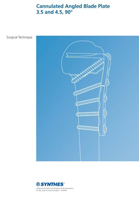
<strong>Cannulated</strong> <strong>Angled</strong> <strong>Blade</strong> <strong>Plate</strong> <strong>3.5</strong> <strong>and</strong> <strong>4.5</strong>, <strong>90°</strong>Implants<strong>Cannulated</strong> <strong>Angled</strong> <strong>Blade</strong> <strong>Plate</strong> <strong>3.5</strong>, <strong>90°</strong>– the cannulated blade allows accurate insertion <strong>and</strong> exactpositioning of the plate– blade geometry <strong>and</strong> oblique lag screw provide for a highrotational stability– blade lengths: 30, 35, 40 <strong>and</strong> 45 mm– number of screw holes: 4, 5, 6, 8 or 10– the three round holes next to the blade are suitable for CortexScrews <strong>3.5</strong> mm or Cancellous Bone Screws 4.0 mm– LC-DCP ® holes for Cortex Screws <strong>3.5</strong> mm– LC-DCP undercuts allow good periosteal blood supply– available in Pure Titanium (432.009–089) orStainless Steel (232.009–089)Guide Wire 2.0 mm with Threaded Tiplength 230 mm (292.650)To determine blade length <strong>and</strong> for exact positioning of blade<strong>and</strong> plate shaft.Cortex Screws <strong>3.5</strong> mm, self-tappingPure Titanium (404.810–910),Stainless Steel (204.810–910)Cortex Screws <strong>3.5</strong> mmPure Titanium (404.010–110),Stainless Steel (204.010–110)Cancellous Bone Screws 4.0 mmPure Titanium (406.010–060),Stainless Steel (206.010–060)Synthes 3
<strong>Cannulated</strong> <strong>Angled</strong> <strong>Blade</strong> <strong>Plate</strong> <strong>4.5</strong>, <strong>90°</strong>– the cannulated blade allows accurate insertion <strong>and</strong> exactpositioning of the plate– blade geometry <strong>and</strong> oblique lag screw provide for a highrotational stability– blade lengths: 30, 40, 50, <strong>and</strong> 60 mm– number of screw holes: 4, 5, 6, 8, 10, or 12– the three round holes next to the blade are suitable for CortexScrews <strong>4.5</strong> mm or Cancellous Bone Screws 6.5 mm– LC-DCP holes for Cortex Screws <strong>4.5</strong> mm– LC-DCP undercuts allow good periosteal blood supply– available in Pure Titanium (437.043–126) orStainless Steel (237.043–126)Guide Wire 2.0 mm with Threaded Tiplength 230 mm (292.650)To determine blade length <strong>and</strong> for exact positioning of blade<strong>and</strong> plate shaft.Cortex Screws <strong>4.5</strong> mm, self-tappingPure Titanium (414.814–940),Stainless Steel (214.814–940)Cortex Screws <strong>4.5</strong> mmPure Titanium (414.014–140),Stainless Steel (214.014–140)Cancellous Bone Screws 6.5 mmPure Titanium (418.020–110),Stainless Steel (218.020–110)4
<strong>Cannulated</strong> <strong>Angled</strong> <strong>Blade</strong> <strong>Plate</strong> <strong>3.5</strong> <strong>and</strong> <strong>4.5</strong>, <strong>90°</strong>Surgical techniqueA proximal humeral fracture is used to demonstrate thefollowing surgical technique for the cannulated angled bladeplate <strong>3.5</strong> <strong>and</strong> <strong>4.5</strong>, <strong>90°</strong>.Since the blade length is determined intraoperatively usingthe guide wire, the use of X-ray templates is not required.1Patient positioningThe patient is positioned in a beach chair position.2Fracture reductionReduce the fracture under image intensifier control.3ApproachThe approach is deltopectoral.4Determine blade entry point <strong>and</strong> insert guide wirePlace the Drill Guide (332.015 or 332.401) on the lateral metaphysisof the proximal humerus <strong>and</strong> insert the Guide Wire 2.0 mm (292.650) through the central hole 2.0 mm ofthe drill guide using the Compact Air Drive with QuickCoupling for Kirschner Wires (511.790). The tip of the guidewire is placed in subchondral position.Check the position of the guide wire with the image intensifier.The position of the guide wire indicates the final positionof the blade in a <strong>90°</strong> angle in relation to the diaphysis.Note: The guide wire may also be inserted without usingthe drill guide. Check position with the image intensifier.Synthes 5
5Determine blade lengthRemove the drill guide, slide the Direct Measuring Devicefor <strong>Cannulated</strong> Screws 7.0 mm (319.210) onto the guidewire <strong>and</strong> read the blade length from the markings of themeasuring device. The length of the plate shaft is chosenaccording to the extent of the fracture.5040 306Open blade entry pointSlide the drill guide again onto the guide wire <strong>and</strong> align withthe humeral metaphysis. Using a drill bit <strong>3.5</strong> or <strong>4.5</strong> mm,drill a hole through the near cortical bone to the left <strong>and</strong> tothe right of the guide wire hole (1 <strong>and</strong> 2).Using a drill bit 2.5 or 3.2 mm, drill through the near corticalbone through the two oblique holes of the drill guidefrom distal to proximal (3 <strong>and</strong> 4).Remove the drill guide. Slide the cannulated Drill Bit <strong>4.5</strong>/2.1 mm (315.690) onto the guide wire <strong>and</strong> drillthrough the remaining cortical bone.1324Note: In order to facilitate the insertion of the blade <strong>and</strong> toachieve an optimal fit of the plate limb to the metaphysis, thecortical bone at the blade entry point has to be removedcompletely.7Contour plateAdapt the aluminium Bending Template (329.917/918/919 or329.905/908/912) to the bone by placing it distally underthe blade entry point. Use bending pliers or a bending iron tocontour the plate to match the bending template, ensuring asnug fit of plate shaft <strong>and</strong> bone. The angle between the guidewire <strong>and</strong> the humeral metaphysis must identically match theangle between the blade <strong>and</strong> the plate shaft.Note: Avoid bending the plate back <strong>and</strong> forth.6
<strong>Cannulated</strong> <strong>Angled</strong> <strong>Blade</strong> <strong>Plate</strong> <strong>3.5</strong> <strong>and</strong> <strong>4.5</strong>, <strong>90°</strong>Surgical technique8Insert plateSlide the angled blade plate onto the guide wire <strong>and</strong> pressthe blade manually through the cortical <strong>and</strong> the cancellousbone until its final position is reached.Remove <strong>and</strong> dispose of the guide wire.Dense bone procedureAttach the Inserter/Extractor (332.016) as close to theplate angle as possible. Slide the blade onto the guide wire<strong>and</strong> press it manually through the opening in the corticalbone. Complete the insertion by slight taps with the SlottedHammer (332.403) onto the inserter/extractor until theplate is in its final position.Note: Additional compression between the proximalfragment of the humeral head <strong>and</strong> the metaphysis can beachieved using the Tension Device (321.120).9Attach plateAs a lag screw, insert a cortex screw <strong>3.5</strong> or <strong>4.5</strong> mm ora cancellous bone screw 4.0 or 6.5 mm obliquely throughthe hole in the angle of the plate. Increase the drill holewidth up to the fracture line to the same size as the outerdiameter of the screw thread, this will act as a gliding hole.To achieve compression between the proximal fragmentof the humeral head <strong>and</strong> the metaphysis, the lag screw has tobe seated in the far cortical bone distal to the fracture.The angled blade plate is secured in its final position byinserting cortex screws <strong>3.5</strong> or <strong>4.5</strong> mm or cancellous bonescrews 4.0 or 6.5 mm into the proximal round holes <strong>and</strong>cortex screws <strong>3.5</strong> or <strong>4.5</strong> mm into the distal LC-DCP holes.The screws are firmly seated in both cortices to achieve stablefixation.Synthes 7
<strong>Cannulated</strong> <strong>Angled</strong> <strong>Blade</strong> <strong>Plate</strong> <strong>3.5</strong> <strong>and</strong> <strong>4.5</strong>, <strong>90°</strong>Implant removalCleaning of instrumentsRemove plateAfter removing all screws attach the Inserter/Extractor(332.016) close to the angle between the plate shaft <strong>and</strong> theblade <strong>and</strong> extract the plate by slightly tapping with theSlotted Hammer (332.403).Cleaning of instrumentsProper functioning of the instruments can be maintainedby careful cleaning.Intraoperatively, the cannulation of the Drill Bit <strong>4.5</strong>/2.1 mm(315.690) is cleaned with the Cleaning Stylet 2.0 mm(319.360). Postoperatively, the instruments are cleaned withthe cleaning stylet 2.0 mm <strong>and</strong> the Cleaning Brush 2.1 mm (319.270).8
Synthes GmbHEimattstrasse 3, CH-4436 Oberdorfwww.synthes.comPresented by:0123036.000.111 SE_028667 AA © Synthes 2006 Printed in Switzerl<strong>and</strong> Subject to modifications.