Barton 199 DPU Manual - Part No. 9A-10030 - Cameron
Barton 199 DPU Manual - Part No. 9A-10030 - Cameron
Barton 199 DPU Manual - Part No. 9A-10030 - Cameron

Create successful ePaper yourself
Turn your PDF publications into a flip-book with our unique Google optimized e-Paper software.
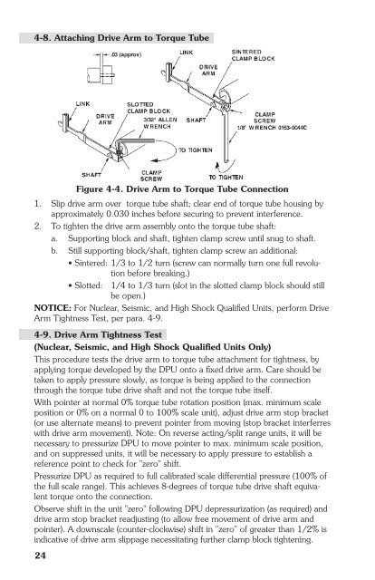
4-8. Attaching Drive Arm to Torque TubeFigure 4-4. Drive Arm to Torque Tube Connection1. Slip drive arm over torque tube shaft; clear end of torque tube housing byapproximately 0.030 inches before securing to prevent interference.2. To tighten the drive arm assembly onto the torque tube shaft:a. Supporting block and shaft, tighten clamp screw until snug to shaft.b. Still supporting block/shaft, tighten clamp screw an additional:• Sintered: 1/3 to 1/2 turn (screw can normally turn one full revolutionbefore breaking.)• Slotted: 1/4 to 1/3 turn (slot in the slotted clamp block should stillbe open.)NOTICE: For Nuclear, Seismic, and High Shock Qualified Units, perform DriveArm Tightness Test, per para. 4-9.4-9. Drive Arm Tightness Test(Nuclear, Seismic, and High Shock Qualified Units Only)This procedure tests the drive arm to torque tube attachment for tightness, byapplying torque developed by the <strong>DPU</strong> onto a fixed drive arm. Care should betaken to apply pressure slowly, as torque is being applied to the connectionthrough the torque tube drive shaft and not the torque tube itself.With pointer at normal 0% torque tube rotation position (max. minimum scaleposition or 0% on a normal 0 to 100% scale unit), adjust drive arm stop bracket(or use alternate means) to prevent pointer from moving (stop bracket interferreswith drive arm movement). <strong>No</strong>te: On reverse acting/split range units, it will benecessary to pressurize <strong>DPU</strong> to move pointer to max. minimum scale position,and on suppressed units, it will be necessary to apply pressure to establish areference point to check for "zero" shift.Pressurize <strong>DPU</strong> as required to full calibrated scale differential pressure (100% ofthe full scale range). This achieves 8-degrees of torque tube drive shaft equivalenttorque onto the connection.Observe shift in the unit "zero" following <strong>DPU</strong> depressurization (as required) anddrive arm stop bracket readjusting (to allow free movement of drive arm andpointer). A downscale (counter-clockwise) shift in "zero" of greater than 1/2% isindicative of drive arm slippage necessitating further clamp block tightening.24