MSE Kompakt I Benutzer- und Installationsanleitung ... - Warema
MSE Kompakt I Benutzer- und Installationsanleitung ... - Warema
MSE Kompakt I Benutzer- und Installationsanleitung ... - Warema

You also want an ePaper? Increase the reach of your titles
YUMPU automatically turns print PDFs into web optimized ePapers that Google loves.
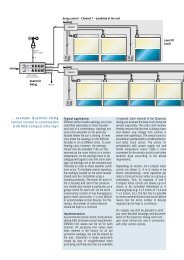
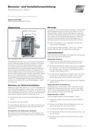
User and installation guide<strong>MSE</strong> <strong>Kompakt</strong> IPlease save these instructions for future use!Valid as from December 22, 200593100130•816908•7852k0•22.12.2005General remarksInformation about the electrical connection:The device fulfills the requirements on immunity to interferenceand emitted interference in residential and commercialareas.CommissioningThe device is ready to operate after the mounting work hasbeen completed and the supply voltage applied.Fig. 1: <strong>MSE</strong> <strong>Kompakt</strong> IThe <strong>MSE</strong> <strong>Kompakt</strong> I motor control unit (MCU) is an electroniccontrol device for controlling of 230V AC sun protectiondrives. The drives and the MCU are supplied by a 230VAC loop cable. The required control voltage of 24 V DC isgenerated in the MCU itself. The connected drives can beoperated locally by means of of a push button. Control bymeans of a sun protection central control unit (CCU), suchas Wisotronic dialog, is also possible. Several MCUs can becombined into a group and controlled together by means ofa push button.Information on theElectrical InstallationWork on the 230V Power supply may only be carried out byqualified electrical personnel (in accordance with VDE 0100).If it is to be assumed that safe operation is not possible, thedevice may not be taken into operation or it must be shutdown. This assumption is to be made if■ the enclosure or the power feeders show signs of damage■ the device no longer operatesResponsibility for observance of the regulations of the nationalutility company as well as observance of the nationalregulations on installation lies with the operator and the personinstalling the electrical system.MountingIn its standard configuration, the MCU is configured for surface-mountedinstallation. Enclosures for flush-mounting,distributed, hollow-wall and moisture-proof assembly arealso available. Electrical connection is to be carried out inaccordance with the wiring diagram overleaf.Function of the <strong>MSE</strong> <strong>Kompakt</strong> ILocal operation with "Time mode":After the "UP" or "DOWN" button has been pressed, thesun blind moves in the corresponding direction and stopsafter approx. 2 seconds. If the button remains pressed, thetime mode function remains locked. The button can thenbe released. The sun blind moves until the set runtime of 3minutes has expired. In order to de-activate the lock modeand stop the motor, the button with the opposite move commandhas to be pressed briefly. The "UP" or "DOWN" buttonhas to be pressed for less than 2 seconds in order to onlyturn the slats of a venetian blindCentral operation:Local operation is blocked for the duration of central operation,whereby any active move command is deleted.Note: Should the drive fail to reach the limit switch "Up" or"Down" within a period of 3 minutes, the drive will automaticallyswitch off, regardless of whether a local or centralcommand was given.Group formation by means of a loop cable: NumerousMCUs can be connected via a loop cable as a group andcontrolled centrally via a pushbutton. Please refer to the wiringdiagram for this on page 3.MaintenanceThere are no parts to be maintained within the device. Incase of a malfunction the installed miniature fuse may onlybe replaced by qualified electrical personnel.LiabilityThe manufacturer can reject the warranty for damage to theproduct if the product information given in these instructionsis not observed, if it is used for purposes other than thosespecified or if used improperly. Liability for consequent damageto persons or property is also excluded in this case.Observe the specifications in the operating instructions ofyour sunblind. Liability for damage to the sunblind caused byoperation during icing or icy conditions is also excluded.93100130•816908•7852k0•22.12.2005 We reserve the right to carry out improvements 1
Usage to the intended purposeThe control system was developed for the control of sunprotection drives. The approval of the manufacturer has tobe obtained if the device is to be used to a purpose differentto that described here.DisposalThe device has to be disposed of or recycledin accordance with the statutory regulations.Technical data<strong>MSE</strong> <strong>Kompakt</strong> I min. typ. max. unitSupply 230 V ACOperating voltage 207 230 253 V ACPower consumption 1 2 mAOutput (drive)Switching capacity at500 VA230 V AC/cos ϕ =0,6Input (Control)Central voltage active 8 24 30 V DCCentral current active 1 1,5 2 mACentral voltage passive -0,5 0 4 V DCLocal voltage active 8 24 30 V DCLocal current active 1 1,5 2 mALocal voltage passive -0,5 0 4 V DCHousingsHollow-wall housingL165xB165xT65Moisture-proof housingL200xB120xT75Standard housings See Fig. 3Degree of protectionSurface-type, flush-type,IP30hollow-wall housingMoisture-proof housingIP54DIN rail-mounted deviceIP20Safety classIConnectionAll connectionsScrewed terminalsTerminalsAll terminals 2,5 mm 2ConformityAmbient conditionsOperating temperature 0 20 40 °CStorage temperature 0 20 50 °CHumidity (non-condensing)10 40 85 %F relArticle numbersIn Surface-type housing 1002 435Matching lid for flushtype317 160housingIn DIN rail-housing 1002 436In hollow-wall housing 1002 437In Moisture-proof1002 438housing2We reserve the right to carry out improvements93100130•816908•7852k0•22.12.2005
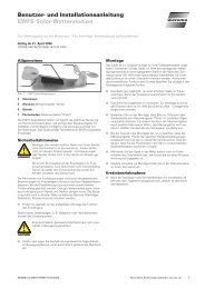
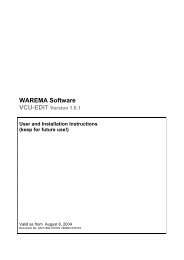
2Motor 1 Motor 2Motor 3 Motor 4M 1~3 12M 1~ 23 1M 1~ 23 1M 1~3 1Caution!Only one drive may be connectedper terminal set. The drive is damagedin case of parallel connections!2222223333331111112233114x 0,75mm 2 UV-resistant 4x 0,75mm 2 UV-resistant 4x 0,75mm 2 UV-resistant 4x 0,75mm 2 UV-resistantBKBNBUGNYEPEN3 x 1,5mm 2 L1Feeder230V AC50Hz/16A3,15 AT<strong>MSE</strong><strong>Kompakt</strong> IPEFloating contact of the sunprotection control unit (CCU)2x2x0,8mmø*P 02 1PEPBKBNBUGNYEBKBNBUGNYEBKBNBUGNYEN PE NN L1 N PE N N L1 N PE N N L1 N PE N N L13,15 AT3,15 AT3,15 AT<strong>MSE</strong><strong>Kompakt</strong> I<strong>MSE</strong><strong>Kompakt</strong> I<strong>MSE</strong><strong>Kompakt</strong> I00+ + P 00+ + P00+ + P00+ + P2 1NP 0L10V+2x2x0,8mmø*2x2x0,8mmø*To further<strong>MSE</strong>/MCULoop cable(central control)8 - 24V DCPCaution! For group formation, connect the Up command and theDown command of the relevant <strong>MSE</strong>s with each other.A maximum of 200 MCU per loop cable (central control) may beconnected. Only pushbuttons may be used!*Screened, twisted pair cable!Group button Single button3x1,5 mm 2Group controlSingle controlFig. 2: Wiring diagram <strong>MSE</strong> <strong>Kompakt</strong> I93100130•816908•7852k0•22.12.2005We reserve the right to carry out improvements3
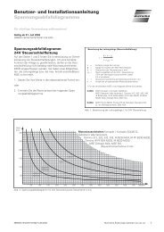
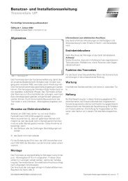
793 pcs. STE 11Lid types:7989BC5265,5175,51891891993 pcs. STE 11Surface-mountedtypeFlush-mountedtype41 mm38 mm34 mm13 mm71 mm96 mmMounting bores 4,2mmøFig. 3: Dimensions standard housings4We reserve the right to carry out improvements93100130•816908•7852k0•22.12.2005