
Create successful ePaper yourself
Turn your PDF publications into a flip-book with our unique Google optimized e-Paper software.
DURBAL Vertriebsgesellschaft mbH<br />
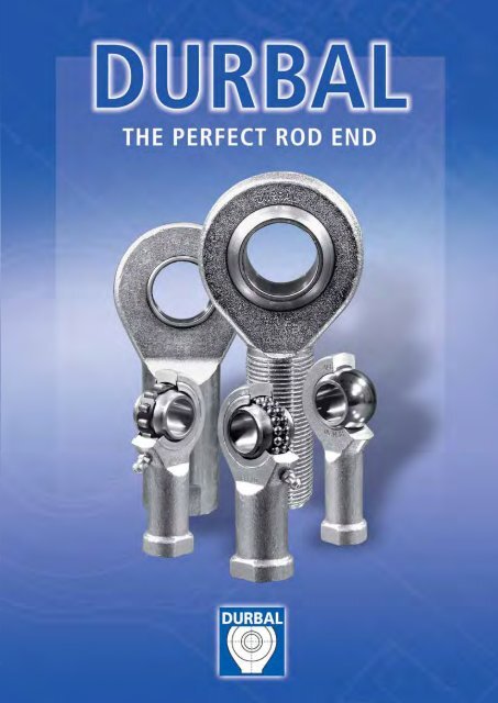
DURBAL ® heavy-duty rod ends are standardized<br />
ready-to-be-installed machine components<br />
serving the transmission of static<br />
and dynamic forces in combination with<br />
swivelling, tilting or rotating movements.<br />
Known under the name »Schlegel«, the rod<br />
ends with integrated self-aligning ball<br />
bearing were initially used in the aircraft<br />
industry. In the meantime our heavy-duty<br />
rod ends have become a standard concept<br />
in all industrial applications under the<br />
name »DURBAL«.<br />
The DURBAL ® heavy-duty rod ends are<br />
distinguished by their high precision and<br />
reliability. The q<strong>ua</strong>lity of DURBAL products is<br />
systematically planned, manufactured and<br />
controlled by the QM-System, which was<br />
2<br />
certified offically in March 1996 and is in<br />
accordance with DIN ISO 9001 which is<br />
valid for all areas of enterprise.<br />
The universal product range is available<br />
ex stock and consists of DURBAL ® heavyduty<br />
rod ends with maintenance-free plain<br />
bearings or low-maintenance antifriction<br />
bearings, offering an optimal choice for a<br />
wide range of different applications.<br />
The selection criteria and calculation basics<br />
contained in this catalogue are based on<br />
numerous endurance test runs and more<br />
than 65 years of experience. This enables<br />
an individ<strong>ua</strong>l adaption of the features of<br />
DURBAL ® heavy-duty rod ends to the<br />
requirements of the corresponding application.<br />
DURBAL ® heavy-duty rod ends are available<br />
with connections in metric dimensions<br />
according to DIN ISO 12240-4, ISO 8139,<br />
or in INCHES. Suitable threaded links facilitate<br />
the installation of DURBAL ® heavy-duty<br />
rod ends.<br />
This catalogue represents the latest state<br />
of our technical and manufacturing developments<br />
and therefore earlier catalogues are<br />
not longer valid. The given specifications<br />
are subject to change due to technical improvements.<br />
Our experienced staff is always at<br />
your service to answer any query you<br />
may have.
Technical introduction<br />
Selection • Definitions • Calculations • Tolerances<br />
DURBAL ® heavy-duty rod ends with integral self-aligning roller bearing BRTM<br />
adapter sizes according to DIN ISO 12240-4, series K BRTF<br />
DURBAL ® heavy-duty rod ends with integral self-aligning ball bearing BRM<br />
adapter sizes according to DIN ISO 12240-4, series K BRF<br />
DURBAL ® heavy-duty rod ends with integral self-aligning ball bearing PM<br />
PF<br />
DURBAL ® heavy-duty rod ends with integral spherical plain bearing<br />
adapter sizes according to DIN ISO 12240-4, series K; maintenance-free BEM<br />
thread according to ISO 8139 BEF<br />
DURBAL ® heavy-duty rod ends with integral spherical plain bearing EM<br />
adapter sizes according to DIN ISO 12240-4, series E / EH; maintenance-free EF<br />
DURBAL ® heavy-duty rod ends with integral self-aligning ball bearing<br />
adapter sizes according to DIN ISO 12240-4, series K BRM<br />
stainless steel BRF<br />
DURBAL ® heavy-duty rod ends with integral spherical plain bearing<br />
adapter sizes according to DIN ISO 12240-4, series K BEM<br />
thread according to ISO 8139 BEF<br />
stainless steel<br />
Table of contents<br />
stainless<br />
steel<br />
stainless<br />
steel<br />
Inches<br />
DURBAL ® heavy-duty rod ends with integral self-aligning ball bearing BRM<br />
dimensions in inches BRF<br />
Inches<br />
DURBAL ® heavy-duty rod ends with integral spherical plain bearing BEM<br />
dimensions in inches; maintenance-free BEF<br />
Inches<br />
DURBAL ® Mountings threaded links for bars GW<br />
washers DDG<br />
threaded bolt BOK<br />
rod linkage <strong>Rod</strong> Linkage<br />
3<br />
page 12<br />
page 13<br />
page 14<br />
page 15<br />
page 16<br />
page 17<br />
page 18<br />
page 19<br />
page 20<br />
page 21<br />
page 22<br />
page 23<br />
page 24<br />
page 25<br />
DURBAL ® heavy-duty rod ends with integral self-aligning roller bearing BRTM page 26<br />
dimensions in inches BRTF page 27<br />
page 28<br />
page 29<br />
page 30<br />
page 31<br />
page 32<br />
page 33<br />
page 34<br />
page 34
Selection<br />
DURBAL ® heavy-duty rod ends are robust, maintenance-free or low-maintenance bearing elements which, considering the selection criteria<br />
described hereafter, impress because of their outstanding working lifes.<br />
DURBAL ® heavy-duty rod ends with<br />
integral self-aligning ball bearing,<br />
series BRM, BRF, PM, PF<br />
This design is especially suitable for high<br />
speeds, large swivelling angles or rotating<br />
movements with relatively low or medium<br />
loads. Prominent technical features are the<br />
low bearing friction, long-term greasing as<br />
well as the sealing against rough dirt penetration<br />
by means of shields on both sides.<br />
Under normal operating conditions the rod<br />
ends are maintenance-free. Lubrication<br />
fittings are provided for lubrication in case<br />
of rough operations and maximum loads.<br />
To avoid incompatibility with the production<br />
lubrication, we recommend lubrication with<br />
a aluminium-complex-soap-grease.<br />
A special heat treatment procedure confers<br />
the rod end housing a raceway hardness<br />
adapted to the antifriction bearing, ensuring<br />
at the same time high stability with changing<br />
loads.<br />
DURBAL ® heavy-duty rod ends with<br />
integral self-aligning roller bearings,<br />
series BRTM, BRTF<br />
The design based on the structure of a selfaligning<br />
roller bearing is preferably used for<br />
high speed, wide tilting angles or rotating<br />
movements under high loads. Compared to<br />
rod ends with self-aligning ball bearings, rod<br />
ends with self-aligning roller bearings have<br />
essentially higher basic load ratings. This<br />
design is equipped with a cage to minimize<br />
the rolling friction and heat built-up. These<br />
rod ends with long-term lubrication are<br />
maintenance-free under normal operating<br />
conditions. Lubrication fittings are provided<br />
for lubrication in case of rough operations<br />
and maximum loads.<br />
To avoid incompatibility with the production<br />
lubrication, we recommend lubricating with<br />
an aluminium-complex-soap-grease. Shields<br />
on both sides prevent dirt particles from<br />
penetrating into the bearing. The rod ends<br />
with self-aligning roller bearings are, just as<br />
the design with self-aligning ball bearings,<br />
4<br />
subjected to a special heat treatment to<br />
obtain a raceway hardness adapted to the<br />
antifriction bearings, ensuring at the same<br />
time a high stability with changing loads.<br />
DURBAL ® heavy-duty rod ends with<br />
integral maintenance-free spherical<br />
plain bearings, series BEM, BEF, EM, EF<br />
In many cases DURBAL ® heavy-duty rod ends<br />
with integrated spherical plain bearings<br />
serve their purpose. They are above all used<br />
for small swivelling or tilting movements at<br />
low speeds. They stand out for their high<br />
loadability and can also be used for shocklike<br />
loads. The rod end ball slides on a bearing<br />
shell consisting of a glass fibre-filled<br />
nylon/teflon compound. This design ensures<br />
an absolutely maintenance-free rod end.<br />
DURBAL ® heavy-duty plain bearing rod ends<br />
have a slight initial stress and virt<strong>ua</strong>lly<br />
no clearance. The compound used has the<br />
favourable secondary advantage to absorb<br />
any foreign particles and to enclose them<br />
that no damage may occur. The joint balls<br />
of DURBAL ® heavy-duty rod ends with<br />
integrated spherical plain bearing are<br />
standardly fitted with a hard chrome plating.<br />
This reliable corrosion protection ensures<br />
that the function of the rod end will not be<br />
affected by a corroded ball surface under<br />
humid operating conditions.<br />
Basic load ratings<br />
Static basic load rating of antifriction<br />
bearing rod ends<br />
The static basic load rating C o of an antifriction<br />
bearing rod end corresponds to that of<br />
a static radial load causing a lasting overall<br />
deformation of 1/10.000 of the roller body<br />
diameter at the contact piont most highly<br />
stressed between roller body and raceway.<br />
Static basic load ratings of plain bearing<br />
rod ends<br />
The static basic load rating C o of a plain<br />
bearing rod end corresponds to the static<br />
radial load that does not yet cause a lasting<br />
deformation at the weakest housing section.<br />
It contains at least a 1.2 fold security compared<br />
to the yield stress of the material used<br />
for the rod end housing.<br />
Dynamic basic load rating of antifriction<br />
bearing rod ends<br />
The dynamic basic load rating C of an antifriction<br />
bearing rod end is the external radial<br />
load, unchangeable in size and direction, at<br />
which 90 % of a large q<strong>ua</strong>ntity of obviously<br />
identical rod ends will reach or exceed 1 million<br />
of rotations or swivelling movements.<br />
Dynamic basic load ratings of plain<br />
bearing rod ends<br />
The dynamic basic load rating C is the parameter<br />
for the calculation of dynamically<br />
loaded maintenance-free DURBAL ® heavyduty<br />
rod ends with integrated spherical plain<br />
bearing, in other words, making tilting,<br />
swivelling or rotating movements under<br />
load.<br />
Basic load ratings always depend on<br />
the definitions they are based on. For<br />
this reason it is not always possible<br />
to compare basic load rating data<br />
supplied by different manufactures.
Operating temperatures<br />
DURBAL ® heavy-duty antifriction bearing rod<br />
ends can be used for operating temperatures<br />
between – 45° C and + 120° C.<br />
The temperature range of DURBAL ® heavyduty<br />
rod ends with integrated spherical plain<br />
bearings is between – 30° C and + 60° C,<br />
without affecting the loadability. Higher<br />
temperatures will reduce the loadability<br />
taken into account for the calculation of the<br />
working life under the temperature factor C 2 .<br />
Loads<br />
The decisive parameters for the selection<br />
and calculation of DURBAL ® heavy-duty rod<br />
ends are size, direction and type of load.<br />
Radial or combined loads<br />
The DURBAL ® heavy-duty rod ends have<br />
been especially designed to adopt high radial<br />
loads.<br />
They can furthermore be used for combined<br />
loads. The axial load share of which does not<br />
exceed 20 % of the corresponding radial<br />
load.<br />
Unilaterally acting load<br />
In this case the load acts only in the same<br />
direction, which means that the load area is<br />
always in the same bearing section.<br />
Alternately acting load<br />
In case of alternating loads, the load<br />
areas facing each other are alternately loaded<br />
and/or relieved, which means that the<br />
load changes its direction constantly by<br />
approx. 180°.<br />
Swivelling angle<br />
The swivelling angle is the excursion of the<br />
rod end from one final position to the other.<br />
Half the swivelling angle β is used to calculate<br />
the service or working life.<br />
Angle of tilt<br />
The angle of tilt, also called setting angle,<br />
refers to the possible excursion of the joint<br />
ball and/or the inner ring to the rod end axis<br />
in degrees. The tilting angle α indicated in<br />
the table for the DURBAL ® heavy-duty antifriction<br />
bearing rod ends corresponds to the<br />
max. possible excursion being limited by the<br />
shields on both sides. It is important that this<br />
tilting angle is not exceeded either during<br />
installation or operation, as otherwise the<br />
shields may be damaged. As far as DURBAL ®<br />
heavy-duty plain bearing rod ends are concerned,<br />
distinction is made between the<br />
tilting angles α 1 and α 2 .<br />
If the excursion is not limited by adjacent<br />
components, excursion angle α 1 can fully<br />
be used without affecting the rod end capacity.<br />
Tilting angle α 2 is the excursion limit<br />
when connecting a forked component.<br />
Nominal service life<br />
The term »nominal service life« is used for<br />
DURBAL ® heavy-duty antifriction bearing rod<br />
ends and represents the number of swivelling<br />
motions or rotations and/or the number<br />
of service hours the rod end performs before<br />
showing the first signs of material fatigue<br />
at the raceway or roller bodies.<br />
Definitions<br />
In view of many influence factors that are<br />
difficult or impossible to assess, the service<br />
life of several obviously identical bearings<br />
differ under the same operating conditions.<br />
For this reason, the following method for<br />
the service life determination of DURBAL ®<br />
heavy-duty antifriction rod ends results in<br />
a nominal service life being achieved or<br />
exceeded by at least 90 % of a larger<br />
q<strong>ua</strong>ntity of identical rod ends.<br />
Working life<br />
The term »working life« is used with<br />
DURBAL ® heavy-duty plain bearing rod ends.<br />
It represents the number of swivelling<br />
motions or rotations and/or the number of<br />
service hours the DURBAL ® heavy-duty plain<br />
bearing rod end performs before becoming<br />
unserviceable because of material fatigue,<br />
wear, increased bearing clearance or increase<br />
of the bearing friction moment. The<br />
working life is not only influenced by the size<br />
and the type of load, it is also affected by<br />
a number of factors, which are partially<br />
difficult to assess. A calculation of the exact<br />
servicelife is therefore impossible. Fieldexperienced<br />
standard values for the approximate<br />
working life can nevertheless be<br />
determined by using the following calculation<br />
procedure which is based on numerous<br />
results from endurance test runs and values<br />
from decades of experience. The values<br />
determined by this formula are achieved,<br />
normally even exceeded, by the majority<br />
of the DURBAL ® heavy-duty rod ends.<br />
The specific loading of rod ends and bearings<br />
differs in each application. Therefore general<br />
statements by a producer in a catalogue may<br />
not totally fit to the single application.<br />
In all cases the user has to coordinate the<br />
theoretical selection criteria with the concrete<br />
installation sit<strong>ua</strong>tion and check the<br />
suitability of the rod end respectively bearing.<br />
In this context the user has to define sufficient<br />
security factors and maintenance<br />
intervals.<br />
5
Calculations<br />
Antifriction bearing construction<br />
DURBAL ® heavy-duty rod ends with integral self-aligning ball bearing<br />
series BRM, BRF, PM, PF<br />
Nominal service life<br />
rotating: (1) oscillating: (2)<br />
Static load<br />
constant: Po � Co [N] (3)<br />
condition:<br />
swivelling angle ß � 3°<br />
For swivelling angles ß � 3°<br />
we recommend the use of<br />
DURBAL ® heavy-duty plain bearing<br />
rod ends.<br />
DURBAL ® heavy-duty rod ends with integral self-aligning roller bearing<br />
series BRTF, BRTM<br />
Nominal service life<br />
rotating: (4) oscillating: (5)<br />
Static load<br />
constant: Po � Co [N]<br />
(6)<br />
6<br />
condition:<br />
swivelling angle ß � 3°<br />
For swivelling angles ß � 3°<br />
we recommend the use of<br />
DURBAL ® heavy-duty plain bearing<br />
rod ends.
Lh rot.<br />
nominal sevice life for rotation [hours of operation]<br />
Lh osz.<br />
nominal service life for oscillating movement [hours or operation]<br />
C basic dynamic load rating [N], see tables<br />
Co basic static load rating [N], see tables<br />
P dynamic equivalent load [N]<br />
P o<br />
rod ends with integral self-aligning ball bearing: P=Fr +y (7) . Fa rod ends with integral self-aligning roller bearing: P=Fr + 9,5 (8) . Fa static equivalent load [N]<br />
rod ends with integral self-aligning ball bearing: Po=Fr +y .<br />
o Fa (9)<br />
rod ends with integral self-aligning roller bearing: Po=Fr +5 (10) . Fa Fa axial load [N]<br />
Fr radial load [N]<br />
Y axial factor, dynamic, see tables<br />
Yo axial factor, static, see tables<br />
β half the swivelling angle [degrees], ß = 90° should be used for rotation<br />
n rotation speed [min -1 ]<br />
f frequency of oscillation [min -1 ]<br />
Calculation example<br />
At the rotating side of a crank mechanism, a DURBAL ® heavy-duty antifriction bearing rod end should be<br />
installed. The expected service life amounts to at least 5,000 hours.<br />
Known: rotation speed n = 300 min -1 , radial load F r = 750 N<br />
Selected: BRF 8<br />
C = 4000 N<br />
Calculations<br />
7
Calculations<br />
Plain bearing construction<br />
Working life<br />
8<br />
G= C .<br />
1 C2 . C3 . 3 . C . 8<br />
10<br />
d .<br />
8 β P<br />
Gh = C .<br />
1 C2 . C3 . 5 . C . 6<br />
10<br />
d .<br />
8 β . f P<br />
G working life [number of<br />
oscillations or revolutions]<br />
G h working life<br />
[hours of operation]<br />
(11)<br />
(12)<br />
C basic dynamic load rating [N],<br />
see tables<br />
d 8 joint ball diameter [mm]<br />
β half the swivelling angle<br />
[degrees], ß = 90° should be<br />
used for rotation<br />
f frequency of oscillation [min -1 ]<br />
C 1 load direction factor,<br />
see following table<br />
C 2 temperature factor,<br />
see following table<br />
C 3 material factor,<br />
see following table<br />
C 4 factor for type of load,<br />
see following table<br />
P equivalent dynamic load [N]<br />
P=F r +F a � P max.<br />
F r radial load component [N]<br />
F a axial load component [N],<br />
condition: F a � 0,2 . F r<br />
P max.maximum permissable<br />
rod end load [N]<br />
P max. = C o . c2 . c4<br />
C o Basic static load rating, [N],<br />
see tables<br />
(13)<br />
(14)<br />
Load direction factor C 1<br />
Single load direction:<br />
C1 = 1,0<br />
alternating load direction,<br />
at f < 30 min -1 : C 1 = 0,25<br />
alternating load direction,<br />
at f > 30 min -1 : C 1 = 0,125<br />
Temperature factor C 2<br />
temperature C 2<br />
up to 60° C 1,0<br />
60° C to 80° C 0,8<br />
80° C to 100° C 0,7<br />
100° C to 110° C 0,6<br />
Material factor C 3<br />
Alignment chart for material factor C 3<br />
Factor fortypee of load C 4<br />
Static load<br />
If DURBAL ® heavy-duty rod ends support<br />
loads whilst stationary or with very little<br />
movement, the maximum permissable load<br />
is not a result of wear but a function of the<br />
material strength of the sliding layer or the<br />
rod end housing.<br />
If static loads are a combination of radial<br />
and axial loads, the equivalent static bearing<br />
load will have to be calculated.<br />
The Calculation is identical with that of<br />
the equivalent dynamic bearing load – see<br />
eq<strong>ua</strong>tion (13), page 8.<br />
Permissable sliding velocity<br />
The permissable sliding velocity of DURBAL ®<br />
heavy-duty rod ends depends mainly on the<br />
load and temperature conditions. Heat<br />
generated through friction in the rod end<br />
housing itself is the main limitation on sliding<br />
velocity. When selecting the rod end size,<br />
it is necessary to determine the sliding velocity<br />
and the pv-value, which is a product of<br />
the specific bearing load p [N/mm 2 ] and the<br />
sliding velocity v [m/s].<br />
The following standard values refer to<br />
swivelling and rotating movements. With<br />
satisfactory cooling, speeds may be increased.<br />
Permissable<br />
pv-value = 0,5 N/mm 2 . m/s<br />
Permissable sliding velocity<br />
v max. = 0,15m/s � V m
Specific bearing load<br />
p = k P .<br />
C<br />
p specific bearing load<br />
[N/mm 2 ]<br />
(15)<br />
P equivalent dynamic load [N],<br />
see eq<strong>ua</strong>tion (13), page 8<br />
C basic dynamic load rating [N],<br />
see tables<br />
k specific load factor [N/mm 2 ]<br />
for sliding contact surfaces<br />
steel on nylon/teflon/fibre glass<br />
k = 50 N/mm 2<br />
Mean sliding velocity<br />
Vm = 5,82 . 10- . 7 d .<br />
8 β . f<br />
V m mean sliding velocity [m/s]<br />
d 8 joint ball diameter [mm],<br />
see tables<br />
β half the swivelling angle<br />
[degrees], β = 90° should<br />
be used for rotation<br />
(16)<br />
f frequency of oscillation [min -1 ]<br />
Calculation example<br />
The rod assembly of a conveyor equipment calls for a DURBAL ® heavy-duty rod end with a<br />
working life of 7000 hours in conjunction with an alternating acting load of 5000 N.<br />
25 swivelling movements with a swivelling angle of 20° take place per minute. The operating<br />
temperature amounts to approx. 60°C.<br />
The choice is a DURBAL ® heavy-duty rod end EF 15 with:<br />
C = 13400 N, d 8 = 22 mm.<br />
Working life<br />
Gh = c .<br />
1 c2 . c3 .<br />
5<br />
.<br />
C<br />
. 6<br />
10<br />
d .<br />
8 β . f P<br />
c 1 = 0,25 (alternating load direction, f = 25 min -1 < 30 min -1 )<br />
c 2 = 1,0 (operating temperature 60° C)<br />
c 3 =<br />
see alignment chart page 8 C 3 = 17<br />
d8 = 22 mm<br />
f = 25 min -1<br />
β = 10° (half the swivelling angle: 20° : 2 = 10°)<br />
C = 13400 N<br />
P = 5000 N<br />
Gh = 0,25<br />
=<br />
. 1,0 . 12 . . . 10 6<br />
5 13400<br />
22 . 10 . 25 5000<br />
7308 h > 7000 h<br />
Checking the permissable load of the rod end<br />
P max.= C o · c 2 · c 4<br />
C o = 41000 N<br />
c 2 = 1,0 (operating temperature 60° C)<br />
c 4 = 0,2 (alternating load)<br />
P max.=<br />
Checking the permissable sliding velocity<br />
Vm =<br />
=<br />
Checking the p · v -value<br />
p =<br />
p . k<br />
Vm =<br />
. = 50 . = 18,66 N/mm2 P 5000<br />
C 13400<br />
18,66 . 0,0032<br />
=<br />
c .<br />
2 = 1,0 . C 13400<br />
= 2,68<br />
P 5000<br />
41000 . 1,0 . 0,2 = 8200 N > 5000 N<br />
5,82 . 10- . 7<br />
d .<br />
8 β . f = 5,82 . 10- 7.<br />
22 . 10 . 25<br />
0,0032 m/s < 0,15 m/s<br />
0,06 N/mm 2 . m/s < 0,5 N/mm 2 . m/s<br />
Calculations<br />
9
Tolerances<br />
DURBAL ® heavy-duty rod ends, series BRM, BRF, BRTM, BRTF, BEM, BEF<br />
Dimension and tolerance symbols<br />
d 1 = nominal bore diameter of the inner ring or joint ball<br />
Δd 1mp = mean bore diameter deviation in one plane, arithmetical mean<br />
of the largest and smallest bore diameter<br />
V d1p<br />
V d1mp<br />
b 1<br />
Δ b1s<br />
10<br />
d 1 Δd 1mp V d1p V d1mp Δ b1s Δ hs, h1s, h2s<br />
tolerance limit tolerance limit tolerance limit<br />
over incl. upper lower max. max. upper lower upper lower<br />
6 +0,012 0 0,012 0,009 0 - 0,12 +1,2 -1,2<br />
6 10 +0,015 0 0,015 0,011 0 - 0,12 +1,2 -1,2<br />
10 18 +0,018 0 0,018 0,014 0 - 0,12 +1,2 -1,2<br />
18 30 +0,021 0 0,021 0,016 0 - 0,12 +1,7 -1,7<br />
30 50 +0,025 0 0,025 0,019 0 - 0,12 +2,1 -2,1<br />
DURBAL ® heavy-duty rod ends, series EM, EF, PM, PF<br />
d 1 Δd 1mp V d1p V d1mp Δ b1s Δ hs, h1s, h2s<br />
tolerance limit tolerance limit tolerance limit<br />
over incl. upper lower max. max. upper lower upper lower<br />
18 0 - 0,008 0,008 0,006 0 - 0,12 +1,2 -1,2<br />
18 30 0 - 0,010 0,010 0,008 0 - 0,12 +1,7 -1,7<br />
30 50 0 - 0,012 0,012 0,009 0 - 0,12 +2,1 -2,1<br />
50 80 0 - 0,015 0,015 0,011 0 - 0,15 +2,7 -2,7<br />
= bore diameter variation in one plane,<br />
difference between the largest and smallest bore diameter<br />
= mean bore diameter variation,<br />
difference between the largest and smallest bore diameter<br />
of one inner ring or joint ball<br />
= inner ring or joint ball width<br />
= single inner ring or joint ball width deviation<br />
h, h1, h2 = system length from inner ring or ball bore center to shank end<br />
Δ hs, Δ h1s, Δ h2s = system length variation of a single rod end
DURBAL ® BRTM<br />
male thread;<br />
long-term<br />
lubrication,<br />
low maintenance,<br />
shields,<br />
adapter sizes<br />
according to<br />
DIN ISO 12240-4,<br />
series K<br />
12<br />
DURBAL ® heavy-duty rod ends<br />
with integral self-aligning<br />
roller bearing<br />
rod end housing:<br />
forged steel, case-hardened bearing race,<br />
superfinished, rolled thread, surface galvanized,<br />
free of Cr VI<br />
inner ring:<br />
ball bearing steel, hardened,<br />
superfinished<br />
lubrication:<br />
aluminium-complex-soap-grease,<br />
temperature range -45 °C to +120 °C,<br />
approval according to USDA H1<br />
lubrication fitting:<br />
DIN 71 412 H1<br />
bearing clearance:<br />
10 - 30 μm radial<br />
tolerances:<br />
see page 10<br />
order number measurements [mm]<br />
type right hand thread left hand thread d 1 d 3 d 4 d 6 b 1 b 3<br />
BRTM 12 -01 -501 -502 12 M 12 14,5 32 16 12<br />
BRTM 16 -03 -501 -502 16 M 16 19,0 42 21 15<br />
BRTM 20 -00 -501 -502 20 M 20 x 1,5 24,5 50 25 18<br />
BRTM 25 -00 -501 -502 25 M 24 x 2 29,5 64 31 22<br />
BRTM 30 -00 -501 -502 30 M 30 x 2 34,5 70 37 25<br />
measurements [mm] weight rotational basic load rating<br />
speed limit dyn. stat.<br />
type h I l 3 α n max C C o<br />
[°] [kg] [min -1 ] [N] [N]<br />
BRTM 12 54 33 19 7,5 0,088 1125 10250 6600<br />
BRTM 16 66 40 22 7,0 0,185 975 13300 8900<br />
BRTM 20 78 47 28 7,0 0,340 825 17000 11700<br />
BRTM 25 94 57 30 5,0 0,596 600 24900 18500<br />
BRTM 30 110 66 35 7,5 0,912 450 32500 24850<br />
Technical changes reserved.
od end housing:<br />
forged steel, case-hardened bearing race,<br />
superfinished, surface galvanized,<br />
free of Cr VI<br />
inner ring:<br />
ball bearing steel, hardened,<br />
superfinished<br />
lubrication:<br />
aluminium-complex-soap-grease,<br />
temperature range -45 °C to +120 °C,<br />
approval according to USDA H1<br />
lubrication fitting:<br />
DIN 71 412 H1<br />
bearing clearance:<br />
10 - 30 μm radial<br />
tolerances:<br />
see page 10<br />
DURBAL ® heavy-duty rod ends<br />
with integral self-aligning<br />
roller bearing<br />
DURBAL ® BRTF<br />
female thread;<br />
long-term<br />
lubrication,<br />
low maintenance,<br />
shields,<br />
adapter sizes<br />
according to<br />
DIN ISO 12240-4,<br />
series K<br />
order number measurements [mm]<br />
type right hand thread left hand thread d 1 d 2 d 3 d 4 d 6 d 7 b 1 b 3<br />
BRTF 12 -04 -501 -502 12 17,5 M 12 14,5 32 22 16 12<br />
BRTF 16 -03 -501 -502 16 22,0 M 16 19,0 42 27 21 15<br />
BRTF 20 -00 -501 -502 20 27,5 M 20 x 1,5 24,5 50 34 25 18<br />
BRTF 25 -00 -501 -502 25 30,0 M 24 x 2 29,5 64 35 31 22<br />
BRTF 30 -01 -501 -502 30 40,0 M 30 x 2 34,5 70 50 37 25<br />
measurements [mm] weight rotational basic load rating<br />
speed limit dyn. stat.<br />
type h I I 1 I 3 SW α n max C C o<br />
[°] [kg] [min -1 ] [N] [N]<br />
BRTF 12 50 22 6,5 16 19 7,5 0,109 1125 10250 6600<br />
BRTF 16 64 28 8,0 22 22 7,0 0,220 975 13300 8900<br />
BRTF 20 77 33 10,0 26 30 7,0 0,361 825 17000 11700<br />
BRTF 25 94 42 10,0 32 30 5,0 0,565 600 24900 18500<br />
BRTF 30 110 51 15,0 35 41 7,5 1,000 450 32500 24850<br />
Technical changes reserved. 13
DURBAL ® BRM<br />
male thread;<br />
long-term<br />
lubrication,<br />
low maintenance,<br />
shields,<br />
adapter sizes<br />
according to<br />
DIN ISO 12240-4,<br />
series K<br />
14<br />
DURBAL ® heavy-duty rod ends<br />
with integral self-aligning<br />
ball bearing<br />
rod end housing:<br />
forged steel, case-hardened bearing race,<br />
superfinished, rolled thread, surface galvanized,<br />
free of Cr VI<br />
inner ring:<br />
ball bearing steel, hardened,<br />
superfinished<br />
lubrication:<br />
aluminium-complex-soap-grease,<br />
temperature range -45 °C to +120 °C,<br />
approval according to USDA H1<br />
lubrication fitting:<br />
DIN 3405 D1/A (sizes 6 to 10)<br />
DIN 71 412 H1 (sizes 12 to 30)<br />
bearing clearance:<br />
10 - 30 μm radial<br />
tolerances:<br />
see page 10<br />
order number measurements [mm]<br />
type right hand thread left hand thread d 1 d 3 d 4 d 6 b 1 b 3 h<br />
BRM 06 -00 -501 -502 6 M 6 9,0 20 9 6,75 36<br />
BRM 08 -00 -501 -502 8 M 8 10,5 24 12 9,0 42<br />
BRM 10 -00 -501 -502 10 M 10 12,0 28 14 10,5 48<br />
BRM 12 -00 -501 -502 12 M 12 14,5 32 16 12,0 54<br />
BRM 14 -00 -501 -502 14 M 14 17,0 36 19 13,5 60<br />
BRM 16 -00 -501 -502 16 M 16 19,0 42 21 15,0 66<br />
BRM 18 -00 -501 -502 18 M 18 x 1,5 21,5 46 23 16,5 72<br />
BRM 20 -00 -501 -502 20 M 20 x 1,5 24,5 50 25 18,0 78<br />
BRM 22 -00 -501 -502 22 M 22 x 1,5 26,0 54 28 20,0 84<br />
BRM 25 -00 -501 -502 25 M 24 x 2 29,5 64 31 22,0 94<br />
BRM 30 -00 -501 -502 30 M 30 x 2 34,5 70 37 25,0 110<br />
measurements[mm] weight calculation- rotational basic load rating<br />
factors speed limit dyn. stat.<br />
type I I 3 α Y Y o n max C C o<br />
[°] [kg] [min -1 ] [N] [N]<br />
BRM 06 22 12 8,0 0,019 2,09 2,19 1350 2750 650<br />
BRM 08 25 15 8,5 0,036 1,80 1,89 1300 4000 1000<br />
BRM 10 29 15 8,0 0,060 1,90 1,81 1225 4450 1450<br />
BRM 12 33 19 7,5 0,087 1,74 1,82 1125 4950 1800<br />
BRM 14 36 20 6,0 0,135 2,36 2,48 1025 5600 2000<br />
BRM 16 40 22 8,0 0,190 2,24 2,35 975 6250 2350<br />
BRM 18 44 25 8,5 0,270 2,21 2,31 900 7100 2900<br />
BRM 20 47 28 7,0 0,338 2,46 2,58 825 7900 3450<br />
BRM 22 51 26 8,0 0,450 2,35 2,24 725 9300 3980<br />
BRM 25 57 30 5,0 0,602 2,02 2,12 600 11030 5680<br />
BRM 30 66 35 7,5 0,922 2,24 2,35 450 14150 7450<br />
Technical changes reserved.
od end housing:<br />
forged steel, case-hardened bearing race,<br />
superfinished, surface galvanized,<br />
free of Cr VI<br />
inner ring:<br />
ball bearing steel, hardened,<br />
superfinished<br />
lubrication:<br />
aluminium-complex-soap-grease,<br />
temperature range -45 °C to +120 °C,<br />
approval according to USDA H1<br />
lubrication fitting:<br />
DIN 3405 D1/A (sizes 6 to 10)<br />
DIN 71 412 H1 (sizes 12 to 30)<br />
bearing clearance:<br />
10 - 30 μm radial<br />
tolerances:<br />
see page 10<br />
DURBAL ® heavy-duty rod ends<br />
with integral self-aligning<br />
ball bearing<br />
DURBAL ® BRF<br />
female thread;<br />
long-term<br />
lubrication,<br />
low maintenance,<br />
shields,<br />
adapter sizes<br />
according to<br />
DIN ISO 12240-4,<br />
series K<br />
order number measurements [mm]<br />
type right hand thread left hand thread d 1 d 2 d 3 d 4 d 6 d 7 b 1 b 3 h<br />
BRF 06 -00 -501 -502 6 10,0 M 6 9,0 20 13 9 6,75 30<br />
BRF 08 -00 -501 -502 8 12,5 M 8 10,5 24 16 12 9,0 36<br />
BRF 10 -00 -501 -502 10 15,0 M 10 12,0 28 19 14 10,5 43<br />
BRF 12 -00 -501 -502 12 17,5 M 12 14,5 32 22 16 12,0 50<br />
BRF 14 -00 -501 -502 14 20,0 M 14 17,0 36 25 19 13,5 57<br />
BRF 16 -00 -501 -502 16 22,0 M 16 19,0 42 27 21 15,0 64<br />
BRF 18 -00 -501 -502 18 25,0 M 18 x 1,5 21,5 46 31 23 16,5 71<br />
BRF 20 -00 -501 -502 20 27,5 M 20 x 1,5 24,5 50 34 25 18,0 77<br />
BRF 22 -00 -501 -502 22 30,0 M 22 x 1,5 26,0 54 38 28 20,0 84<br />
BRF 25 -00 -501 -502 25 30,0 M 24 x 2 29,5 64 35 31 22,0 94<br />
BRF 30 -00 -501 -502 30 40,0 M 30 x 2 34,5 70 50 37 25,0 110<br />
measurements [mm] weight calculation- rotational basic load rating<br />
factors speed limit dyn. stat.<br />
type I I 1 I 3 SW α Y Y o n max C C o<br />
[°] [kg] [min -1 ] [N] [N]<br />
BRF 06 12 5,0 10 11 8,0 0,024 2,09 2,19 1350 2750 650<br />
BRF 08 16 5,0 12 14 8,5 0,044 1,80 1,89 1300 4000 1000<br />
BRF 10 20 6,5 15 17 8,0 0,072 1,90 1,81 1225 4450 1450<br />
BRF 12 22 6,5 16 19 7,5 0,107 1,74 1,82 1125 4950 1800<br />
BRF 14 25 8,0 20 22 6,0 0,160 2,36 2,48 1025 5600 2000<br />
BRF 16 28 8,0 22 22 8,0 0,224 2,24 2,35 975 6250 2350<br />
BRF 18 32 10,0 24 27 8,5 0,293 2,21 2,31 900 7100 2900<br />
BRF 20 33 10,0 26 30 7,0 0,367 2,46 2,58 825 7900 3450<br />
BRF 22 37 12,0 26 32 8,0 0,480 2,35 2,24 725 9300 3980<br />
BRF 25 42 10,0 32 30 5,0 0,572 2,02 2,12 600 11030 5680<br />
BRF 30 51 15,0 35 41 7,5 0,978 2,24 2,35 450 14150 7450<br />
Technical changes reserved. 15
DURBAL ® PM<br />
male thread;<br />
long-term<br />
lubrication,<br />
low maintenance,<br />
shields<br />
DURBAL ® heavy-duty rod ends<br />
with integral self-aligning<br />
ball bearing<br />
rod end housing:<br />
forged steel, case-hardened bearing race,<br />
superfinished, rolled thread, surface galvanized,<br />
free of Cr VI<br />
inner ring:<br />
ball bearing steel, hardened,<br />
superfinished<br />
lubrication:<br />
aluminium-complex-soap-grease,<br />
temperature range -45 °C to +120 °C,<br />
approval according to USDA H1<br />
lubrication fitting:<br />
DIN 3405 D1/A<br />
bearing clearance:<br />
10 - 30 μm radial<br />
tolerances:<br />
see page 10<br />
order number measurements [mm]<br />
type right hand thread left hand thread d 1 d 3 d 4 d 6 d 7 b 1 b 3<br />
PM 05 -00 -501 -502 5 M 8 x 1 7,5 19 12 12 8<br />
PM 05 -01 -501 -502 5 M 8 x 1 7,5 19 12 12 8<br />
PM 06 -00 -501 -502 6 M 10 x 1 8,5 24 14 14 10<br />
PM 06 -02 -501 -502 6 M 10 x 1 8,5 24 14 14 10<br />
PM 08 -00 -501 -502 8 M 12 x 1,5 11,0 30 17 15 10<br />
PM 08 -02 -501 -502 8 M 12 x 1,5 11,0 30 17 15 10<br />
PM 10 -00 -501 -502 10 M 14 x 1,5 13,5 36 19 20 14<br />
PM 10 -03 -501 -502 10 M 14 x 1,5 13,5 36 19 20 14<br />
PM 12 -00 -501 -502 12 M 16 x 1,5 15,0 40 21 20 14<br />
PM 12 -02 -501 -502 12 M 16 x 1,5 15,0 40 21 20 14<br />
PM 15 -00 -501 -502 15 M 20 x 1,5 18,5 42 26 20 14<br />
PM 15 -02 -501 -502 15 M 20 x 1,5 18,5 42 26 20 14<br />
PM 17 -00 -501 -502 17 M 20 x 1,5 21,0 48 26 22 16<br />
PM 17 -01 -501 -502 17 M 20 x 1,5 21,0 48 26 22 16<br />
PM 20 -00 -501 -502 20 M 24 x 1,5 24,0 56 30 24 18<br />
PM 20 -02 -501 -502 20 M 24 x 1,5 24,0 56 30 24 18<br />
measurements [mm] weight calculation- rotational basic load rating<br />
factors speed limit dyn. stat.<br />
type l 1 l 2 l 3 h 1 h 2 u z α Y Y o n max C C o<br />
[°] [kg] [min -1 ] [N] [N]<br />
PM 05 39,5 13 57 1,5 2,5 7,0 0,037 1,51 1,58 1350 1610 480<br />
PM 05 16 13 33,5 1,5 2,5 7,0 0,033 1,51 1,58 1350 1610 480<br />
PM 06 42,5 17 64 1,5 2,5 10,5 0,062 1,28 1,34 1300 2445 765<br />
PM 06 19 17 40,5 1,5 2,5 10,5 0,057 1,28 1,34 1300 2445 765<br />
PM 08 46,5 20 72 2,0 2,5 8,5 0,097 1,9 1,81 1225 2605 985<br />
PM 08 23 20 48,5 2,0 2,5 8,5 0,088 1,9 1,81 1225 2605 985<br />
PM 10 49,5 28 82 2,5 2,5 9,5 0,168 1,69 1,77 1100 5120 1905<br />
PM 10 26 28 58,5 2,5 2,5 9,5 0,154 1,69 1,77 1100 5120 1905<br />
PM 12 53,5 31 90 3,0 2,5 7,5 0,226 1,81 1,90 1050 5345 2065<br />
PM 12 29 31 65,5 3,0 2,5 7,5 0,204 1,81 1,90 1050 5345 2065<br />
PM 15 62,5 30 100 3,0 2,5 6,5 0,310 2,07 2,17 975 5485 3270<br />
PM 15 36 30 73,5 3,0 2,5 6,5 0,273 2,07 2,17 975 5485 3270<br />
PM 17 62,5 36 105 3,5 2,5 7,0 0,401 2,35 2,46 875 5575 2680<br />
PM 17 36 36 78,5 3,5 2,5 7,0 0,354 2,35 2,46 875 5575 2680<br />
PM 20 68,5 41 117 3,5 3,0 5,5 0,587 2,76 2,90 775 6165 3140<br />
PM 20 41 41 89,5 3,5 3,0 5,5 0,519 2,76 2,90 775 6165 3140<br />
16<br />
Technical changes reserved.
od end housing:<br />
forged steel, case-hardened bearing race,<br />
superfinished, surface galvanized,<br />
free of Cr VI<br />
inner ring:<br />
ball bearing steel, hardened,<br />
superfinished<br />
lubrication:<br />
aluminium-complex-soap-grease,<br />
temperature range -45 °C to +120 °C,<br />
approval according to USDA H1<br />
lubrication fitting:<br />
DIN 3405 D1/A<br />
bearing clearance:<br />
10 - 30 μm radial<br />
tolerances:<br />
see page 10<br />
DURBAL ® heavy-duty rod ends<br />
with integral self-aligning<br />
ball bearing<br />
DURBAL ® PF<br />
female thread;<br />
long-term<br />
lubrication,<br />
low maintenance,<br />
shields<br />
order number measurements [mm]<br />
type right hand thread left hand thread d 1 d 2 d 3 d 4 d 6 b 1 b 3<br />
PF 10 -00 -501 -502 10 15 M 8 13,0 30 13,0 9<br />
PF 15 -00 -501 -502 15 19 M 12 17,5 40 16,5 12<br />
PF 20 -00 -501 -502 20 22 M 16 24,0 48 20,5 15<br />
measurements [mm] weight calculation- rotational basic load rating<br />
factors speed limit dyn. stat.<br />
type h I I 3 r SW α Y Y o n max C C o<br />
[°] [kg] [min -1 ] [N] [N]<br />
PF 10 38 17 14,5 10 13 7,0 0,063 1,90 1,81 1225 2605 985<br />
PF 15 51 24 20,0 15 17 7,0 0,140 2,30 2,41 1025 5000 1890<br />
PF 20 65 32 22,0 20 19 6,5 0,223 2,34 2,45 850 6105 2955<br />
Technical changes reserved. 17
DURBAL ® BEM<br />
male thread;<br />
maintenance free,<br />
adapter sizes<br />
according to<br />
DIN ISO 12240-4,<br />
series K<br />
18<br />
DURBAL ® heavy-duty rod ends<br />
with integral spherical<br />
plain bearing<br />
1) angle of tilt, see page 5<br />
rod end housing:<br />
forged steel, tempered, rolled thread,<br />
surface galvanized, free of Cr VI<br />
joint ball:<br />
ball bearing steel, hardened and ground,<br />
surface superfinished and chromium<br />
plated<br />
race:<br />
nylon / teflon / glass fibre compound<br />
tolerances:<br />
see page 10<br />
order number measurements [mm]<br />
type right hand thread left hand thread d 1 d 3 d 6 d 8 b 1 b 3<br />
BEM 05 -20 -501 -502 5 M 5 18 11,06 8 6,0<br />
BEM 06 -20 -501 -502 6 M 6 20 12,65 9 6,75<br />
BEM 08 -20 -501 -502 8 M 8 24 15,82 12 9,0<br />
BEM 10 -20 -501 -502 10 M 10 28 19,00 14 10,5<br />
BEM 12 -20 -501 -502 12 M 12 32 22,17 16 12,0<br />
BEM 14 -20 -501 -502 14 M 14 36 25,35 19 13,5<br />
BEM 16 -20 -501 -502 16 M 16 42 28,52 21 15,0<br />
BEM 18 -20 -501 -502 18 M 18 x 1,5 46 31,70 23 16,5<br />
BEM 20 -20 -501 -502 20 M 20 x 1,5 50 34,87 25 18,0<br />
BEM 22 -20 -501 -502 22 M 22 x 1,5 54 38,05 28 20,0<br />
BEM 25 -20 -501 -502 25 M 24 x 2 60 42,80 31 22,0<br />
BEM 30 -20 -501 -502 30 M 30 x 2 70 50,75 37 25,0<br />
measurements [mm] weight basic load rating<br />
dyn. stat.<br />
type h I l 3 α 1 1) α 2 1) C C o<br />
[°] [°] [kg] [N] [N]<br />
BEM 05 33 20 9 13,0 7,5 0,014 3910 5600<br />
BEM 06 36 22 12 13,0 6,5 0,020 4590 7800<br />
BEM 08 42 25 15 14,5 7,5 0,038 6965 14300<br />
BEM 10 48 29 15 13,5 8,0 0,060 10420 22600<br />
BEM 12 54 33 19 13,0 8,0 0,092 12425 32800<br />
BEM 14 60 36 20 16,0 9,5 0,127 15440 41300<br />
BEM 16 66 40 22 15,5 8,5 0,202 22410 56600<br />
BEM 18 72 44 25 15,0 9,5 0,250 26325 69700<br />
BEM 20 78 47 28 14,5 9,0 0,327 30805 82200<br />
BEM 22 84 51 26 15,5 10,0 0,440 38230 95600<br />
BEM 25 94 57 30 15,0 10,0 0,630 45350 118600<br />
BEM 30 110 66 35 17,0 10,5 1,015 55010 145600<br />
Technical changes reserved.
od end housing:<br />
forged steel, tempered, surface galvanized,<br />
free of Cr VI<br />
joint ball:<br />
ball bearing steel, hardened and ground,<br />
surface superfinished and chromium<br />
plated<br />
race:<br />
nylon / teflon / glass fibre compound<br />
tolerances:<br />
see page 10<br />
DURBAL ® heavy-duty rod ends<br />
with integral spherical<br />
plain bearing<br />
DURBAL ® BEF<br />
female thread;<br />
maintenance free,<br />
adapter sizes<br />
according to<br />
DIN ISO 12240-4,<br />
series K,<br />
thread according to<br />
ISO 8139<br />
order number measurements [mm]<br />
type right hand thread left hand thread d 1 d 2 d 3 d 6 d 7 d 8 b 1 b 3<br />
BEF 05 -20 -501 -502 5 9,0 M 5 18 11 11,06 8 6,0<br />
BEF 05 SO -22 -501 -502 5 9,0 M 4 18 11 11,06 8 6,0<br />
BEF 06 -20 -501 -502 6 10,0 M 6 20 13 12,65 9 6,75<br />
BEF 08 -20 -501 -502 8 12,5 M 8 24 16 15,82 12 9,0<br />
BEF 10 -20 -501 -502 10 15,0 M 10 28 19 19,00 14 10,5<br />
BEF 10 SO -21 -501 -502 10 15,0 M 10 x 1,25 28 19 19,00 14 10,5<br />
BEF 12 -20 -501 -502 12 17,5 M 12 32 22 22,17 16 12,0<br />
BEF 12 SO -22 -501 -502 12 17,5 M 12 x 1,25 32 22 22,17 16 12,0<br />
BEF 14 -20 -501 -502 14 20,0 M 14 36 25 25,35 19 13,5<br />
BEF 16 -20 -501 -502 16 22,0 M 16 42 27 28,52 21 15,0<br />
BEF 16 SO -21 -501 -502 16 22,0 M 16 x 1,5 42 27 28,52 21 15,0<br />
BEF 18 -20 -501 -502 18 25,0 M 18 x 1,5 46 31 31,70 23 16,5<br />
BEF 20 -20 -501 -502 20 27,5 M 20 x 1,5 50 34 34,87 25 18,0<br />
BEF 22 -20 -501 -502 22 30,0 M 22 x 1,5 54 38 38,05 28 20,0<br />
BEF 25 -20 -501 -502 25 33,5 M 24 x 2 60 42 42,80 31 22,0<br />
BEF 30 -20 -501 -502 30 40,0 M 30 x 2 70 50 50,75 37 25,0<br />
BEF 30 SO -22 -501 -502 30 40,0 M 27 x 2 70 50 50,75 37 25,0<br />
measurements [mm] weight basic load rating<br />
dyn. stat.<br />
type h I l 1 l 3 SW α 1 1) α 2 1) C C o<br />
[°] [°] [kg] [N] [N]<br />
BEF 05 27 10 4,0 10 9 13,0 7,5 0,018 3910 10800<br />
BEF 05 SO 27 10 4,0 10 9 13,0 7,5 0,018 3910 10800<br />
BEF 06 30 12 5,0 10 11 13,0 6,5 0,024 4590 12800<br />
BEF 08 36 16 5,0 12 14 14,5 7,5 0,045 6965 19200<br />
BEF 10 43 20 6,5 15 17 13,5 8,0 0,074 10420 27400<br />
BEF 10 SO 43 20 6,5 15 17 13,5 8,0 0,074 10420 27400<br />
BEF 12 50 22 6,5 16 19 13,0 8,0 0,109 12425 33400<br />
BEF 12 SO 50 22 6,5 16 19 13,0 8,0 0,109 12425 33400<br />
BEF 14 57 25 8,0 20 22 16,0 9,5 0,155 15440 41300<br />
BEF 16 64 28 8,0 22 22 15,5 8,5 0,233 22410 59600<br />
BEF 16 SO 64 28 8,0 22 22 15,5 8,5 0,233 22410 59600<br />
BEF 18 71 32 10,0 24 27 15,0 9,5 0,310 26325 69700<br />
BEF 20 77 33 10,0 26 30 14,5 9,0 0,386 30805 82200<br />
BEF 22 84 37 12,0 26 32 15,5 10,0 0,520 38230 95600<br />
BEF 25 94 42 12,0 30 36 15,0 10,0 0,705 45350 118600<br />
BEF 30 110 51 15,0 35 41 17,0 10,5 1,084 55010 145600<br />
BEF 30 SO 110 51 15,0 35 41 17,0 10,5 1,084 55010 145600<br />
Technical changes reserved. 1)<br />
angle of tilt, see page 5<br />
19
DURBAL ® EM<br />
male thread;<br />
maintenance free,<br />
adapter sizes<br />
according to<br />
DIN ISO 12240-4,<br />
series E / EH<br />
DURBAL ® heavy-duty rod ends<br />
with integral spherical<br />
plain bearing<br />
rod end housing:<br />
forged steel, tempered, rolled thread,<br />
surface galvanized, free of Cr VI<br />
joint ball:<br />
ball bearing steel, hardened and ground,<br />
surface superfinished and chromium<br />
plated<br />
race:<br />
nylon / teflon / glass fibre compound<br />
tolerances:<br />
see page 10<br />
order number measurements [mm]<br />
type right hand thread left hand thread d 1 d 3 d 6 d 8 b 1 b 3 h<br />
EM 06 -20 -501 -502 6 M 6 20 10,0 6 4 36<br />
EM 08 -20 -501 -502 8 M 8 23 13,0 8 5 42<br />
EM 10 -20 -501 -502 10 M 10 28 16,0 9 6 48<br />
EM 12 -20 -501 -502 12 M 12 32 18,0 10 7 54<br />
EM 15 -20 -501 -502 15 M 14 38 22,0 12 9 63<br />
EM 17 -20 -501 -502 17 M 16 44 25,0 14 10 69<br />
EM 20 -20 -501 -502 20 M 20 x 1,5 51 29,0 16 12 78<br />
EM 25 -20 -501 -502 25 M 24 x 2 62 35,5 20 16 94<br />
EM 30 -20 -501 -502 30 M 30 x 2 70 40,7 22 18 110<br />
EM 35 -20 -501 -502 35 M 36 x 3 82 47,0 25 20 140<br />
EM 40 -20 -501 -502 40 M 42 x 3 92 53,0 28 22 145<br />
EM 40 SO -21 -501 -502 40 M 39 x 3 92 53,0 28 22 150<br />
EM 45 -20 -501 -502 45 M 45 x 3 102 60,0 32 25 165<br />
EM 45 SO -22 -501 -502 45 M 42 x 3 102 60,0 32 25 163<br />
EM 50 -20 -501 -502 50 M 52 x 3 112 66,0 35 28 195<br />
EM 50 SO -22 -501 -502 50 M 45 x 3 112 66,0 35 28 185<br />
EM 60 -20 -501 -502 60 M 60 x 4 135 80,0 44 36 225<br />
EM 60 SO -21 -501 -502 60 M 52 x 3 135 80,0 44 36 210<br />
measurements [mm] weight basic load rating<br />
dyn. stat.<br />
type I l3 1) 1) α1 α2 [°] [°] [kg]<br />
C Co [N] [N]<br />
EM 06 22 11 13,0 6,5 0,014 2500 6400<br />
EM 08 25 12 15,0 8,0 0,024 4200 11000<br />
EM 10 29 15 12,0 6,0 0,041 6400 16800<br />
EM 12 33 15 10,5 5,0 0,067 9200 23000<br />
EM 15 36 18 8,5 4,5 0,110 13400 39600<br />
EM 17 40 23 10,0 5,5 0,163 19200 54100<br />
EM 20 47 25 9,0 4,5 0,270 25200 76700<br />
EM 25 57 32 7,5 3,5 0,508 42400 119100<br />
EM 30 66 35 6,0 3,0 0,785 54000 141800<br />
EM 35 92 38 6,5 3,5 1,330 70400 180800<br />
EM 40 94 42 7,0 3,5 1,890 86000 222600<br />
EM 40 SO 99 42 7,0 3,5 1,785 86000 222600<br />
EM 45 100 50 7,5 4,0 2,620 107000 276200<br />
EM 45 SO 98 50 7,5 4,0 2,430 107000 276200<br />
EM 50 120 60 6,5 3,0 3,865 132000 339200<br />
EM 50 SO 110 60 6,5 3,0 3,225 132000 339200<br />
EM 60 140 70 6,5 3,5 6,400 208000 532100<br />
EM 60 SO 125 70 6,5 3,5 5,430 208000 532100<br />
20<br />
1)<br />
angle of tilt, see page 5<br />
Technical changes reserved.
od end housing:<br />
forged steel, tempered, surface galvanized,<br />
free of Cr VI<br />
joint ball:<br />
ball bearing steel, hardened and ground,<br />
surface superfinished and chromium<br />
plated<br />
race:<br />
nylon / teflon / glass fibre compound<br />
tolerances:<br />
see page 10<br />
DURBAL ® heavy-duty rod ends<br />
with integral spherical<br />
plain bearing<br />
DURBAL ® EF<br />
female thread;<br />
maintenance free,<br />
adapter sizes<br />
according to<br />
DIN ISO 12240-4,<br />
series E / EH<br />
order number measurements [mm]<br />
type right hand thread left hand thread d 1 d 2 d 3 d 6 d 8 b 1 b 3 h<br />
EF 06 -20 -501 -502 6 10 M 6 20 10,0 6 4 30<br />
EF 08 -20 -501 -502 8 13 M 8 23 13,0 8 5 36<br />
EF 10 -20 -501 -502 10 16 M 10 28 16,0 9 6 43<br />
EF 10 SO -22 -501 -502 10 16 M 10 x 1,25 28 16,0 9 6 43<br />
EF 12 -20 -501 -502 12 19 M 12 32 18,0 10 7 50<br />
EF 12 SO -22 -501 -502 12 19 M 12 x 1,25 32 18,0 10 7 50<br />
EF 15 -20 -501 -502 15 22 M 14 38 22,0 12 9 61<br />
EF 17 -20 -501 -502 17 25 M 16 44 25,0 14 10 67<br />
EF 20 -20 -501 -502 20 28 M 20 x 1,5 51 29,0 16 12 77<br />
EF 25 -20 -501 -502 25 35 M 24 x 2 62 35,5 20 16 94<br />
EF 30 -20 -501 -502 30 42 M 30 x 2 70 40,7 22 18 110<br />
EF 35 -20 -501 -502 35 51 M 36 x 3 82 47,0 25 20 125<br />
EF 35 SO -22 -501 -502 35 51 M 36 x 2 82 47,0 25 20 130<br />
EF 40 -20 -501 -502 40 60 M 42 x 3 92 53,0 28 22 145<br />
EF 40 SO -22 -501 -502 40 52 M 39 x 3 92 53,0 28 22 142<br />
EF 45 -20 -501 -502 45 67 M 45 x 3 102 60,0 32 25 165<br />
EF 45 SO -21 -501 -502 45 58 M 42 x 3 102 60,0 32 25 145<br />
EF 50 -20 -501 -502 50 72 M 52 x 3 112 66,0 35 28 195<br />
EF 50 SO -21 -501 -502 50 62 M 45 x 3 112 66,0 35 28 160<br />
EF 60 -20 -501 -502 60 84 M 60 x 4 135 80,0 44 36 225<br />
EF 60 SO -21 -501 -502 60 71 M 52 x 3 135 80,0 44 36 175<br />
measurements [mm] weight basic load rating<br />
dyn. stat.<br />
type l l 3 l 4 l 5 SW α 1 1) α 2 1) C C o<br />
[°] [°] [kg] [N] [N]<br />
EF 06 12 11 9 13,0 6,5 0,017 2500 10600<br />
EF 08 16 12 11 15,0 8,0 0,031 4200 13100<br />
EF 10 20 13 14 12,0 6,0 0,054 6400 18800<br />
EF 10 SO 20 13 14 12,0 6,0 0,054 6400 18800<br />
EF 12 22 15 17 10,5 5,0 0,086 9200 28000<br />
EF 12 SO 22 15 17 10,5 5,0 0,086 9200 28000<br />
EF 15 25 18 19 8,5 4,5 0,142 13400 41000<br />
EF 17 28 20 22 10,0 5,5 0,208 19200 57900<br />
EF 20 33 23 24 9,0 4,5 0,290 25200 76700<br />
EF 25 42 30 30 7,5 3,5 0,573 42400 119100<br />
EF 30 51 32 36 6,0 3,0 0,908 54000 141800<br />
EF 35 38 36 61 41 6,5 3,5 1,230 70400 180800<br />
EF 35 SO 38 41 66 41 6,5 3,5 1,230 70400 180800<br />
EF 40 42 42 71 50 7,0 3,5 2,075 86000 222600<br />
EF 40 SO 42 39 66 46 7,0 3,5 1,880 86000 222600<br />
EF 45 50 45 76 55 7,5 4,0 3,085 107000 276200<br />
EF 45 SO 50 42 66 50 7,5 4,0 2,500 107000 276200<br />
EF 50 60 52 89 60 6,5 3,0 3,975 132000 339200<br />
EF 50 SO 60 45 69 55 6,5 3,0 3,200 132000 339200<br />
EF 60 70 60 103 70 6,5 3,5 7,300 208000 532100<br />
EF 60 SO 70 52 71 60 6,5 3,5 5,900 208000 532100<br />
Technical changes reserved. 1)<br />
angle of tilt, see page 5<br />
21
DURBAL ® BRM stainless steel<br />
male thread;<br />
long-term<br />
lubrication,<br />
low maintenance,<br />
shields,<br />
adapter sizes<br />
according to<br />
DIN ISO 12240-4,<br />
series K<br />
22<br />
DURBAL ® heavy-duty rod ends<br />
with integral self-aligning<br />
ball bearing in stainless steel<br />
rod end housing:<br />
stainless steel 1.4034, hardened, bearing<br />
race superfinished, rolled thread<br />
inner ring:<br />
stainless steel, hardened,<br />
surface superfinished<br />
lubrication:<br />
aluminium-complex-soap-grease,<br />
temperature range -45 °C to +120 °C,<br />
approval according to USDA H1<br />
lubrication fitting:<br />
DIN 3405 D1/A (sizes 6 to 10)<br />
DIN 71 412 H1 (sizes 12 to 20)<br />
bearing clearance:<br />
10 - 30 μm radial<br />
tolerances:<br />
see page 10<br />
order number measurements [mm]<br />
type right hand thread left hand thread d 1 d 3 d 4 d 6 b 1 b 3 h<br />
BRM 06 -60 -501 -502 6 M 6 9,0 20 9 6,75 36<br />
BRM 08 -60 -501 -502 8 M 8 10,5 24 12 9,0 42<br />
BRM 10 -60 -501 -502 10 M 10 12,0 28 14 10,5 48<br />
BRM 12 -60 -501 -502 12 M 12 14,5 32 16 12,0 54<br />
BRM 16 -60 -501 -502 16 M 16 19,0 42 21 15,0 66<br />
BRM 20 -60 -501 -502 20 M 20 x 1,5 24,5 50 25 18,0 78<br />
measurements [mm] weight calculation- rotational basic load rating<br />
factors speed limit dyn. stat.<br />
type I I 3 α Y Y o n max C C o<br />
[°] [kg] [min -1 ] [N] [N]<br />
BRM 06 22 12 8,0 0,019 2,09 2,19 1350 1900 450<br />
BRM 08 25 15 8,5 0,036 1,80 1,89 1300 2800 700<br />
BRM 10 29 15 8,0 0,060 1,90 1,81 1225 3100 1000<br />
BRM 12 33 19 7,5 0,087 1,74 1,82 1125 3450 1250<br />
BRM 16 40 22 8,0 0,190 2,24 2,35 975 4250 1600<br />
BRM 20 47 28 7,0 0,338 2,46 2,58 825 5350 2300<br />
Technical changes reserved.
od end housing:<br />
stainless steel 1.4034, hardened, bearing<br />
race superfinished<br />
inner ring:<br />
stainless steel, hardened,<br />
surface superfinished<br />
lubrication:<br />
aluminium-complex-soap-grease,<br />
temperature range -45 °C to +120 °C,<br />
approval according to USDA H1<br />
lubrication fitting:<br />
DIN 3405 D1/A (sizes 6 to 10)<br />
DIN 71 412 H1 (sizes 12 to 20)<br />
bearing clearance:<br />
10 - 30 μm radial<br />
tolerances:<br />
see page 10<br />
stainless steel DURBAL ® BRF<br />
DURBAL ® heavy-duty rod ends<br />
with integral self-aligning<br />
ball bearing in stainless steel<br />
female thread;<br />
long-term<br />
lubrication,<br />
low maintenance,<br />
shields,<br />
adapter sizes<br />
according to<br />
DIN ISO 12240-4,<br />
series K<br />
order number measurements [mm]<br />
type right hand thread left hand thread d 1 d 2 d 3 d 4 d 6 d 7 b 1 b 3 h<br />
BRF 06 -60 -501 -502 6 10,0 M 6 9,0 20 13 9 6,75 30<br />
BRF 08 -60 -501 -502 8 12,5 M 8 10,5 24 16 12 9,0 36<br />
BRF 10 -60 -501 -502 10 15,0 M 10 12,0 28 19 14 10,5 43<br />
BRF 12 -60 -501 -502 12 17,5 M 12 14,5 32 22 16 12,0 50<br />
BRF 16 -60 -501 -502 16 22,0 M 16 19,0 42 27 21 15,0 64<br />
BRF 20 -60 -501 -502 20 27,5 M 20 x 1,5 24,5 50 34 25 18,0 77<br />
measurements [mm] weight calculation- rotational basic load rating<br />
factors speed limit dyn. stat.<br />
type I I 1 I 3 SW α Y Y o n max C C o<br />
[°] [kg] [min -1 ] [N] [N]<br />
BRF 06 12 5,0 10 11 8,0 0,024 2,09 2,19 1350 1900 450<br />
BRF 08 16 5,0 12 14 8,5 0,044 1,80 1,89 1300 2800 700<br />
BRF 10 20 6,5 15 17 8,0 0,072 1,90 1,81 1225 3100 1000<br />
BRF 12 22 6,5 16 19 7,5 0,107 1,74 1,82 1125 3450 1250<br />
BRF 16 28 8,0 22 22 8,0 0,224 2,24 2,35 975 4250 1600<br />
BRF 20 33 10,0 26 30 7,0 0,367 2,46 2,58 825 5350 2300<br />
Technical changes reserved. 23
DURBAL ® BEM stainless steel<br />
male thread;<br />
maintenance free,<br />
adapter sizes<br />
according to<br />
DIN ISO 12240-4,<br />
series K<br />
24<br />
DURBAL ® heavy-duty rod ends<br />
with integral spherical<br />
plain bearing in stainless steel<br />
rod end housing:<br />
stainless steel 1.4301, rolled thread,<br />
surface with pickling treatment<br />
joint ball:<br />
stainless steel, hardened and ground,<br />
surface superfinished<br />
race:<br />
nylon / teflon / glass fibre compound<br />
tolerances:<br />
see page 10<br />
order number measurements [mm]<br />
type right hand thread left hand thread d 1 d 3 d 6 d 8 b 1 b 3<br />
BEM 05 -60 -501 -502 5 M 5 18 11,06 8 6,0<br />
BEM 06 -60 -501 -502 6 M 6 20 12,65 9 6,75<br />
BEM 08 -60 -501 -502 8 M 8 24 15,82 12 9,0<br />
BEM 10 -60 -501 -502 10 M 10 28 19,00 14 10,5<br />
BEM 12 -60 -501 -502 12 M 12 32 22,17 16 12,0<br />
BEM 14 -60 -501 -502 14 M 14 36 25,35 19 13,5<br />
BEM 16 -60 -501 -502 16 M 16 42 28,52 21 15,0<br />
BEM 18 -60 -501 -502 18 M 18 x 1,5 46 31,70 23 16,5<br />
BEM 20 -60 -501 -502 20 M 20 x 1,5 50 34,87 25 18,0<br />
BEM 22 -60 -501 -502 22 M 22 x 1,5 54 38,05 28 20,0<br />
BEM 25 -60 -501 -502 25 M 24 x 2 60 42,80 31 22,0<br />
BEM 30 -60 -501 -502 30 M 30 x 2 70 50,75 37 25,0<br />
measurements [mm] weight basic load rating<br />
dyn. stat.<br />
type h I l 3 α 1 1) α 2 1) C C o<br />
[°] [°] [kg] [N] [N]<br />
BEM 05 33 20 9 13,0 7,5 0,014 2400 3500<br />
BEM 06 36 22 12 13,0 6,5 0,020 2820 4900<br />
BEM 08 42 25 15 14,5 7,5 0,038 4280 8800<br />
BEM 10 48 29 15 13,5 8,0 0,060 6400 14000<br />
BEM 12 54 33 19 13,0 8,0 0,092 7600 20300<br />
BEM 14 60 36 20 16,0 9,5 0,127 9480 27600<br />
BEM 16 66 40 22 15,5 8,5 0,202 13760 37700<br />
BEM 18 72 44 25 15,0 9,5 0,250 16160 46500<br />
BEM 20 78 47 28 14,5 9,0 0,327 18960 54800<br />
BEM 22 84 51 26 15,5 10,0 0,440 23480 63600<br />
BEM 25 94 57 30 15,0 10,0 0,630 27860 79100<br />
BEM 30 110 66 35 17,0 10,5 1,015 33800 97100<br />
1) angle of tilt, see page 5<br />
Technical changes reserved.
od end housing:<br />
stainless steel 1.4301, rolled thread,<br />
surface with pickling treatment<br />
joint ball:<br />
stainless steel, hardened and ground,<br />
surface superfinished<br />
race:<br />
nylon / teflon / glass fibre compound<br />
tolerances:<br />
see page 10<br />
stainless steel DURBAL ® BEF<br />
DURBAL ® heavy-duty rod ends<br />
with integral spherical<br />
plain bearing in stainless steel<br />
female thread;<br />
maintenance free,<br />
adapter sizes<br />
according to<br />
DIN ISO 12240-4,<br />
series K,<br />
thread according to<br />
ISO 8139<br />
order number measurements [mm]<br />
type right hand thread left hand thread d 1 d 2 d 3 d 6 d 7 d 8 b 1 b 3<br />
BEF 05 -60 -501 -502 5 9,0 M 5 18 11 11,06 8 6,0<br />
BEF 05SO -61 -501 -502 5 9,0 M 4 18 11 11,06 8 6,0<br />
BEF 06 -60 -501 -502 6 10,0 M 6 20 13 12,65 9 6,75<br />
BEF 08 -60 -501 -502 8 12,5 M 8 24 16 15,82 12 9,0<br />
BEF 10 -60 -501 -502 10 15,0 M 10 28 19 19,00 14 10,5<br />
BEF 10SO -61 -501 -502 10 15,0 M 10 x 1,25 28 19 19,00 14 10,5<br />
BEF 12 -60 -501 -502 12 17,5 M 12 32 22 22,17 16 12,0<br />
BEF 12SO -61 -501 -502 12 17,5 M 12 x 1,25 32 22 22,17 16 12,0<br />
BEF 14 -60 -501 -502 14 20,0 M 14 36 25 25,35 19 13,5<br />
BEF 16 -60 -501 -502 16 22,0 M 16 42 27 28,52 21 15,0<br />
BEF 16SO -61 -501 -502 16 22,0 M 16 x 1,5 42 27 28,52 21 15,0<br />
BEF 18 -60 -501 -502 18 25,0 M 18 x 1,5 46 31 31,70 23 16,5<br />
BEF 20 -60 -501 -502 20 27,5 M 20 x 1,5 50 34 34,87 25 18,0<br />
BEF 22 -60 -501 -502 22 30,0 M 22 x 1,5 54 38 38,05 28 20,0<br />
BEF 25 -60 -501 -502 25 33,5 M 24 x 2 60 42 42,80 31 22,0<br />
BEF 30 -60 -501 -502 30 40,0 M 30 x 2 70 50 50,75 37 25,0<br />
BEF 30SO -61 -501 -502 30 40,0 M 27 x 2 70 50 50,75 37 25,0<br />
measurements [mm] weight basic load rating<br />
dyn. stat.<br />
type h I l1 l3 SW 1) α1 [°]<br />
1) α2 [°]<br />
C Co [kg] [N] [N]<br />
BEF 05 27 10 4,0 10 9 13,0 7,5 0,018 2400 7200<br />
BEF 05SO 27 10 4,0 10 9 13,0 7,5 0,018 2400 7200<br />
BEF 06 30 12 5,0 10 11 13,0 6,5 0,024 2820 8500<br />
BEF 08 36 16 5,0 12 14 14,5 7,5 0,045 4280 12800<br />
BEF 10 43 20 6,5 15 17 13,5 8,0 0,074 6400 18300<br />
BEF 10SO 43 20 6,5 15 17 13,5 8,0 0,074 6400 18300<br />
BEF 12 50 22 6,5 16 19 13,0 8,0 0,109 7600 22300<br />
BEF 12SO 50 22 6,5 16 19 13,0 8,0 0,109 7600 22300<br />
BEF 14 57 25 8,0 20 22 16,0 9,5 0,155 9480 27600<br />
BEF 16 64 28 8,0 22 22 15,5 8,5 0,233 13760 39700<br />
BEF 16SO 64 28 8,0 22 22 15,5 8,5 0,233 13760 39700<br />
BEF 18 71 32 10,0 24 27 15,0 9,5 0,310 16160 46500<br />
BEF 20 77 33 10,0 26 30 14,5 9,0 0,386 18960 54800<br />
BEF 22 84 37 12,0 26 32 15,5 10,0 0,520 23480 63600<br />
BEF 25 94 42 12,0 30 36 15,0 10,0 0,705 27860 79100<br />
BEF 30 110 51 15,0 35 41 17,0 10,5 1,084 33800 97100<br />
BEF 30SO 110 51 15,0 35 41 17,0 10,5 1,084 33800 97100<br />
Technical changes reserved. 1)<br />
angle of tilt, see page 5<br />
25
DURBAL ® BRTM dimensions in inches<br />
male thread;<br />
long-term<br />
lubrication,<br />
low maintenance,<br />
shields,<br />
dimensions in inches<br />
26<br />
DURBAL ® heavy-duty rod ends<br />
with integral self-aligning<br />
roller bearing<br />
rod end housing:<br />
forged steel, case-hardened bearing race,<br />
superfinished, rolled thread, surface galvanized,<br />
free of Cr VI<br />
inner ring:<br />
ball bearing steel, hardened,<br />
superfinished<br />
lubrication:<br />
aluminium-complex-soap-grease,<br />
temperature range -45 °C to +120 °C,<br />
approval according to USDA H1<br />
lubrication fitting:<br />
DIN 71 412 H1<br />
bearing clearance:<br />
10 - 30 μm radial<br />
tolerances:<br />
see page 10<br />
order number measurements [inches]<br />
type right hand thread left hand thread d 1 d 3 d 4 d 6 b 1 b 3<br />
class 2<br />
BRTM 1/2 -00 -501 -502 .500 .5000-20 UNF .574 1.311 .624 .472<br />
BRTM 5/8 -00 -501 -502 .625 .6250-18 UNF .748 1.653 .826 .590<br />
BRTM 3/4 -00 -501 -502 .750 .7500-16 UNF .956 1.968 .984 .708<br />
BRTM 1/1 -00 -501 -502 1.000 1.0000-12 UNF 1.161 2.519 1.220 .866<br />
BRTM 1/1 -01 -501 -502 1.000 1.0000-14 UNS 1.161 2.519 1.220 .866<br />
measurements [inches] weight rotational basic load rating<br />
speed limit dyn. stat.<br />
type h I l 3 α n max C C o<br />
[°] [kg] [min -1 ] [N] [N]<br />
BRTM 1/2 2.460 1.496 .846 7,5 0,109 1125 10250 6600<br />
BRTM 5/8 2.618 1.574 .944 7,0 0,182 975 13300 8900<br />
BRTM 3/4 3.090 1.850 1.102 7,0 0,341 825 16655 11445<br />
BRTM 1/1 3.720 2.244 1.279 5,0 0,590 600 24900 18500<br />
BRTM 1/1 3.720 2.244 1.279 5,0 0,590 600 24900 18500<br />
Technical changes reserved.
od end housing:<br />
forged steel, case-hardened bearing race,<br />
superfinished, surface galvanized,<br />
free of Cr VI<br />
inner ring:<br />
ball bearing steel, hardened,<br />
superfinished<br />
lubrication:<br />
aluminium-complex-soap-grease,<br />
temperature range -45 °C to +120 °C,<br />
approval according to USDA H1<br />
lubrication fitting:<br />
DIN 71 412 H1<br />
bearing clearance:<br />
10 - 30 μm radial<br />
tolerances:<br />
see page 10<br />
dimensions in inches DURBAL ® BRTF<br />
DURBAL ® heavy-duty rod ends<br />
with integral self-aligning<br />
roller bearing<br />
female thread;<br />
long-term<br />
lubrication,<br />
low maintenance,<br />
shields,<br />
dimensions in inches<br />
order number measurements [inches]<br />
type right hand thread left hand thread d 1 d 2 d 3 d 4 d 6 d 7 b 1 b 3<br />
class 2<br />
BRTF 1/2 -00 -501 -502 .500 .748 .5000-20 UNF .574 1.311 .874 .624 .472<br />
BRTF 5/8 -00 -501 -502 .625 .866 .6250-18 UNF .748 1.653 1.063 .826 .590<br />
BRTF 3/4 -00 -501 -502 .750 1.082 .7500-16 UNF .956 1.968 1.338 .984 .708<br />
BRTF 1/1 -00 -501 -502 1.000 1.171 1.0000-12 UNF 1.161 2.519 1.377 1.220 .866<br />
BRTF 1/1 -01 -501 -502 1.000 1.171 1.0000-14 UNS 1.161 2.519 1.377 1.220 .866<br />
measurements [inches] weight rotational basic load rating<br />
speed limit dyn. stat.<br />
type h I I 1 I 3 SW α n max C C o<br />
[°] [kg] [min -1 ] [N] [N]<br />
BRTF 1/2 2.145 1.102 .251 .649 .757 7,5 0,127 1125 10250 6600<br />
BRTF 5/8 2.539 1.110 .350 .885 .866 7,0 0,218 975 13300 8900<br />
BRTF 3/4 3.051 1.299 .409 1.043 1.181 7,0 0,386 825 16655 11445<br />
BRTF 1/1 3.720 1.653 .236 1.279 1.181 5,0 0,568 600 24900 18500<br />
BRTF 1/1 3.720 1.653 .236 1.279 1.181 5,0 0,568 600 24900 18500<br />
Technical changes reserved. 27
DURBAL ® BRM dimensions in inches<br />
male thread;<br />
long-term<br />
lubrication,<br />
low maintenance,<br />
shields,<br />
dimensions in inches<br />
DURBAL ® heavy-duty rod ends<br />
with integral self-aligning<br />
ball bearing<br />
rod end housing:<br />
forged steel, case-hardened bearing race,<br />
superfinished, rolled thread, surface galvanized,<br />
free of Cr VI<br />
inner ring:<br />
ball bearing steel, hardened,<br />
superfinished<br />
lubrication:<br />
aluminium-complex-soap-grease,<br />
temperature range -45 °C to +120 °C,<br />
approval according to USDA H1<br />
lubrication fitting:<br />
DIN 3405 D1/A (sizes 1/4 und 3/8)<br />
DIN 71 412 H1 (sizes 1/2 und 1/1)<br />
bearing clearance:<br />
10 - 30 μm radial<br />
tolerances:<br />
see page 10<br />
order number measurements [inches]<br />
type right hand thread left hand thread d 1 d 3 d 4 d 6 b 1 b 3<br />
class 2<br />
BRM 1/4 -00 -501 -502 .250 .2500-28 UNF .356 .787 .354 .265<br />
BRM 3/8 -00 -501 -502 .375 .3750-24 UNF .468 1.102 .551 .413<br />
BRM 1/2 -00 -501 -502 .500 .5000-20 UNF .574 1.311 .624 .472<br />
BRM 5/8 -00 -501 -502 .625 .6250-18 UNF .744 1.653 .826 .590<br />
BRM 3/4 -00 -501 -502 .750 .7500-16 UNF .956 1.968 .984 .708<br />
BRM 1/1 -00 -501 -502 1.000 1.0000-12 UNF 1.161 2.519 1.220 .866<br />
BRM 1/1 -01 -501 -502 1.000 1.0000-14 UNS 1.161 2.519 1.220 .866<br />
measurements [inches] weight calculation- rotational basic load rating<br />
factors speed limit dyn. stat.<br />
type h I I 3 α Y Y o n max C C o<br />
[°] [kg] [min -1 ] [N] [N]<br />
BRM 1/4 1.437 .866 .551 8,0 0,022 2,09 2,19 1350 2670 645<br />
BRM 3/8 1.909 1.141 .748 8,0 0,060 1,87 1,83 1225 4360 1425<br />
BRM 1/2 2.460 1.496 .846 7,5 0,109 1,74 1,82 1125 4850 1850<br />
BRM 5/8 2.618 1.574 .944 8,0 0,200 2,24 2,35 975 6250 2350<br />
BRM 3/4 3.090 1.850 1.102 7,0 0,341 2,32 2,43 825 7750 3380<br />
BRM 1/1 3.720 2.244 1.279 5,0 0,590 2,02 2,12 600 11030 5680<br />
BRM 1/1 3.720 2.244 1.279 5,0 0,590 2,02 2,12 600 11030 5680<br />
28<br />
Technical changes reserved.
od end housing:<br />
forged steel, case-hardened bearing race,<br />
superfinished, surface galvanized,<br />
free of Cr VI<br />
inner ring:<br />
ball bearing steel, hardened,<br />
superfinished<br />
lubrication:<br />
aluminium-complex-soap-grease,<br />
temperature range -45 °C to +120 °C,<br />
approval according to USDA H1<br />
lubrication fitting:<br />
DIN 3405 D1/A (sizes 1/4 und 3/8)<br />
DIN 71 412 H1 (sizes 1/2 und 1/1)<br />
bearing clearance:<br />
10 - 30 μm radial<br />
tolerances:<br />
see page 10<br />
dimensions in inches DURBAL ® BRF<br />
DURBAL ® heavy-duty rod ends<br />
with integral self-aligning<br />
ball bearing<br />
female thread;<br />
long-term<br />
lubrication,<br />
low maintenance,<br />
shields,<br />
dimensions in inches<br />
order number measurements [inches]<br />
type right hand thread left hand thread d 1 d 2 d 3 d 4 d 6 d 7 b 1 b 3<br />
class 2<br />
BRF 1/4 -00 -501 -502 .250 .393 .2500-28 UNF .356 .787 .511 .354 .265<br />
BRF 3/8 -00 -501 -502 .375 .590 .3750-24 UNF .468 1.102 .748 .551 .413<br />
BRF 1/2 -00 -501 -502 .500 .748 .5000-20 UNF .574 1.311 .874 .624 .472<br />
BRF 5/8 -00 -501 -502 .625 .866 .6250-18 UNF .744 1.653 1.062 .826 .590<br />
BRF 3/4 -00 -501 -502 .750 1.000 .7500-16 UNF .956 1.750 1.125 .984 .688<br />
BRF 1/1 -00 -501 -502 1.000 1.171 1.0000-12 UNF 1.161 2.519 1.377 1.220 .866<br />
BRF 1/1 -01 -501 -502 1.000 1.171 1.0000-14 UNS 1.161 2.519 1.377 1.220 .866<br />
measurements [inches] weight calculation- rotational basic load rating<br />
factors speed limit dyn. stat.<br />
type h I I 1 I 3 SW α Y Y o n max C C o<br />
[°] [kg] [min -1 ] [N] [N]<br />
BRF 1/4 1.200 .472 .240 .452 .433 8,0 0,027 2,09 2,19 1350 2670 645<br />
BRF 3/8 1.712 .787 .299 .590 .669 8,0 0,072 1,87 1,83 1225 4360 1425<br />
BRF 1/2 2.145 1.102 .279 .649 .757 7,5 0,127 1,74 1,82 1125 4850 1850<br />
BRF 5/8 2.539 1.102 .322 .885 .866 8,0 0,220 2,24 2,35 975 6250 2350<br />
BRF 3/4 3.051 1.299 .409 .854 1.007 7,0 0,390 2,32 2,43 825 7750 3380<br />
BRF 1/1 3.720 1.653 .236 1.279 1.181 5,0 0,570 2,02 2,12 600 11030 5680<br />
BRF 1/1 3.720 1.653 .236 1.279 1.181 5,0 0,570 2,02 2,12 600 11030 5680<br />
Technical changes reserved. 29
DURBAL ® BEM dimensions in inches<br />
male thread; DURBAL<br />
maintenance free,<br />
dimensions in inches<br />
® heavy-duty rod ends<br />
with integral spherical<br />
plain bearing<br />
30<br />
rod end housing:<br />
forged steel, tempered, rolled thread,<br />
surface galvanized, free of Cr VI<br />
joint ball:<br />
ball bearing steel, hardened and ground,<br />
surface superfinished and chromium<br />
plated<br />
race:<br />
nylon / teflon / glass fibre compound<br />
tolerances:<br />
see page 10<br />
order number measurements [inches]<br />
type right hand thread left hand thread d 1 d 3 d 6 d 8 b 1 b 3<br />
class 2<br />
BEM 1/4 -20 -501 -502 .250 .2500-28 UNF .750 .516 .374 .283<br />
BEM 3/8 -20 -501 -502 .375 .3750-24 UNF 1.000 .719 .499 .405<br />
BEM 1/2 -20 -501 -502 .500 .5000-20 UNF 1.311 .876 .624 .472<br />
BEM 5/8 -20 -501 -502 .625 .6250-18 UNF 1.654 1.125 .827 .590<br />
BEM 3/4 -20 -501 -502 .750 .7500-16 UNF 1.750 1.249 .874 .688<br />
BEM 1/1 -20 -501 -502 1.000 1.0000-12 UNF 2.362 1.688 1.220 .866<br />
BEM 1/1 -21 -501 -502 1.000 1.0000-14 UNS 2.362 1.688 1.220 .866<br />
measurements [inches] weight basic load rating<br />
dyn. stat.<br />
type h I l 3 α 1 1) α 2 1) C C 0<br />
[°] [°] [kg] [N] [N]<br />
BEM 1/4 1.594 1.000 .511 17,5 8,0 0,022 3610 9030<br />
BEM 3/8 1.948 1.240 .629 9,5 5,5 0,049 7650 19120<br />
BEM 1/2 2.460 1.500 .846 13,0 9,5 0,109 14649 36624<br />
BEM 5/8 2.618 1.574 .944 15,5 8,5 0,202 22410 56020<br />
BEM 3/4 2.893 1.750 1.023 11,0 7,0 0,249 24870 62175<br />
BEM 1/1 3.720 2.244 1.200 15,5 10,0 0,562 45350 113380<br />
BEM 1/1 3.720 2.244 1.200 15,5 10,0 0,562 45350 113380<br />
1) angle of tilt, see page 5<br />
Technical changes reserved.
od end housing:<br />
forged steel, tempered, surface galvanized,<br />
free of Cr VI<br />
joint ball:<br />
ball bearing steel, hardened and ground,<br />
surface superfinished and chromium<br />
plated<br />
race:<br />
nylon / teflon / glass fibre compound<br />
tolerances:<br />
see page 10<br />
dimensions in inches DURBAL ® BEF<br />
DURBAL ® heavy-duty rod ends<br />
with integral spherical<br />
plain bearing<br />
female thread;<br />
maintenance free,<br />
dimensions in inches<br />
order number measurements [inches]<br />
type right hand thread left hand thread d 1 d 2 d 3 d 6 d 7 d 8 b 1 b 3<br />
class 2<br />
BEF 1/4 -20 -501 -502 .250 .374 .2500-28 UNF .750 .469 .516 .374 .283<br />
BEF 3/8 -20 -501 -502 .375 .567 .3750-24 UNF 1.000 .689 .719 .499 .405<br />
BEF 1/2 -20 -501 -502 .500 .748 .5000-20 UNF 1.311 .874 .876 .624 .472<br />
BEF 5/8 -20 -501 -502 .625 .866 .6250-18 UNF 1.654 1.063 1.125 .826 .590<br />
BEF 3/4 -20 -501 -502 .750 1.000 .7500-16 UNF 1.750 1.126 1.249 .874 .688<br />
BEF 1/1 -20 -501 -502 1.000 1.319 1.0000-12 UNF 2.362 1.654 1.688 1.220 .866<br />
BEF 1/1 -21 -501 -502 1.000 1.319 1.0000-14 UNS 2.362 1.654 1.688 1.220 .866<br />
measurements [inches] weight basic load rating<br />
dyn. stat.<br />
type h I l 1 l 3 SW α 1 1) α 2 1) C C o<br />
[°] [°] [kg] [N] [N]<br />
BEF 1/4 1.338 .716 .185 .385 .381 17,5 8,0 0,027 4290 11400<br />
BEF 3/8 1.641 .874 .275 .503 .570 9,5 5,5 0,059 7650 20300<br />
BEF 1/2 2.145 1.161 .279 .649 .757 13,0 9,5 0,127 14649 39000<br />
BEF 5/8 2.539 1.102 .350 .885 .866 15,5 8,5 0,231 22410 69600<br />
BEF 3/4 2.905 1.718 .311 .854 1.007 11,0 7,0 0,229 24870 66200<br />
BEF 1/1 3.720 1.653 .511 1.200 1.417 15,5 10,0 0,663 45350 118600<br />
BEF 1/1 3.720 1.653 .511 1.200 1.417 15,5 10,0 0,663 45350 118600<br />
Technical changes reserved. 1)<br />
angle of tilt, see page 5<br />
31
DURBAL ® GW<br />
Threaded links<br />
32<br />
material:<br />
tube DIN 2391 - St 35 BK<br />
order number measurements [mm] breaking yield<br />
load stress<br />
type right hand thread left hand thread d1 d2 d3 l1 l2 l3 s<br />
[N] [N]<br />
GW08 -00 -001 -002 M 8 12 15 8 17 33 2,5 27725 17250<br />
GW08 -01 -001 -002 M 8 x 1 12 15 8 17 33 2,5 27725 17250<br />
GW10 -00 -001 -002 M 10 14 18 10 24 40 2,5 32265 20700<br />
GW10 -01 -001 -002 M 10 x 1 14 18 10 24 40 2,5 32265 20700<br />
GW12 -00 -001 -002 M 12 16 20 12 27 48 2,5 38815 24155<br />
GW12 -01 -001 -002 M 12 x 1,5 16 20 12 27 48 2,5 38815 24155<br />
GW14 -00 -001 -002 M 14 18 22 14 28 56 2,5 44365 27605<br />
GW14 -01 -001 -002 M 14 x 1,5 18 22 14 28 56 2,5 44365 27605<br />
GW16 -00 -001 -002 M 16 20 25 16 33 64 2,5 49905 31060<br />
GW16 -01 -001 -002 M 16 x 1,5 20 25 16 33 64 2,5 49905 31060<br />
GW20 -00 -001 -002 M 20 x 1,5 24 30 20 41 72 2,5 60995 37950<br />
GW24 -01 -001 -002 M 24 x 2 28 35 24 48 82 3,0 72090 44855<br />
GW30 -00 -001 -002 M 30 x 2 34 42 30 60 102 3,0 87890 54685<br />
Technical changes reserved.
seal:<br />
neoprene rubber<br />
washer:<br />
stainless steel<br />
Ø A ± 0,13<br />
T ± 0,13<br />
H ± 0,25<br />
Ø B ± 0,13<br />
Ø C ± 0,2,5<br />
order number measurements [mm]<br />
DURBAL ® DDG<br />
Washers<br />
type A B C H T<br />
± 0,13 ± 0,13 ± 0,25 ± 0,25 ± 0,13<br />
DDG 05 -00 -100 5,25 8,28 11,22 2,41 0,50<br />
DDG 06 -00 -100 6,25 9,53 12,7 3,05 0,69<br />
DDG 08 -00 -100 8,25 12,37 17,78 5,08 1,20<br />
DDG 10 -00 -100 10,25 13,46 20,32 5,59 1,20<br />
DDG 12 -00 -100 12,25 18,54 28,58 6,35 1,20<br />
DDG 14 -00 -100 14,25 20,32 29,21 6,86 1,20<br />
DDG 16 -00 -100 16,25 22,40 31,7 6,80 1,20<br />
DDG 18 -00 -100 18,25 22,60 32,69 8,25 1,20<br />
DDG 20 -00 -100 20,25 25,15 38,10 10,16 1,20<br />
DDG 25 -00 -100 25,25 33,80 53,30 12,70 1,50<br />
DDG 30 -00 -100 30,25 35,56 55,88 13,97 1,53<br />
Technical changes reserved. 33
DURBAL ® threaded bolt & rod linkage<br />
Threaded Bolt<br />
In addition to the DURBAL ® heavy-duty rod<br />
ends series K DURBAL supplies a threaded<br />
bolt. The bolt can be supplied already fixed to<br />
the required rod end.<br />
34<br />
order number measurements [mm] weight<br />
type size L L 1 L 2 G D SW<br />
BOK 06 18,5 13 10 M 6 9,0 8 10<br />
BOK 08 23,5 17 13 M 8 10,5 8 12<br />
BOK 10 28,0 21 17 M 10 13,0 12 25<br />
[g/bolt]<br />
BOK 12 32,5 25 20 M 12 15,0 14 40<br />
BOK 14 37,5 29 22 M 14 17,0 14 65<br />
BOK 16 42,5 33 24 M 16 19,0 17 90<br />
BOK 20 57,0 45 35 M 20 x 1,5 24,0 22 200<br />
When ordering this constellation please use the catalogue designation of the required rod end along with the type of the fitting threaded bolt.<br />
Example: you need a DURBAL ® integral spherical plain bearing BEM 10 incl. threaded bolt:<br />
text of order: BEM 10-20-501 + BOK 10<br />
<strong>Rod</strong> Linkage<br />
To simplify installation you can use already<br />
mounted rod linkages.<br />
Please define the desired system as described<br />
in the table below:<br />
DURBAL ® heavy duty length of rod linkage system length DURBAL ® heavy duty<br />
rod end 1 L LS rod end 2<br />
Upon your request you will receive the rod linkage with male thread respectively pipe construction to reduce weight.<br />
Technical changes reserved.
Conditions of Delivery and Payment<br />
1. General<br />
1.1. Only our conditions for delivery and payment are valid unless otherwise<br />
specified in our order confirmation. Deviating conditions for<br />
purchasing the customer may have will not become term of the<br />
contract with the acceptance of the order.<br />
1.2. If a specific term of these conditions is or becomes invalid, all remaining<br />
conditions shall remain valid.<br />
1.3. Modifications of the contract or side agreements will be applicable<br />
only if confirmed in writing.<br />
2. Conclusion of the Contract<br />
2.1. All our offers are without obligation.<br />
2.2. Contracts are accepted with the dispatch of our order confirmation<br />
and apply accordingly.<br />
3. Delivery<br />
3.1. Delivering times are not binding for us.<br />
3.2. For agreed delivery times the period for delivery begins on the day on<br />
which we receive the written consent between the customer and the<br />
supplier and the customer has provided the supplier with all documents<br />
and items needed for the execution of the contract.<br />
3.3. The compliance with the agreed delivery time takes place under<br />
reserve of correct and timely self supply of the supplier.<br />
3.4. The delivery date is considered met if the delivery item is brought or<br />
fetched for shipping within the agreed period. If the handover is<br />
delayed due to reasons the customer is responsible for, the delivery<br />
date is considered met with the notification of the readiness for<br />
dispatch.<br />
3.5. If the shipping or turnover of the delivery item is delayed due to<br />
reasons the customer is responsible for, he has to compensate the<br />
supplier for any costs incurred due to the delay. The supplier is entitled<br />
to bill these costs after the expiration of ten days counting from the<br />
day of notification of the readiness for dispatch or turnover.<br />
3.6. If the delivery date cannot be met due to reasons the supplier is not<br />
responsible for or due to unexpected events, the period will be<br />
reasonably extended.<br />
3.7. If the supplier cannot meet the delivery date (delay in delivery), the<br />
customer is entitled to rescission and/or amends only after a reasonable<br />
period of grace has been set.<br />
4. Shipping<br />
4.1. The shipment is made on account and at the risk of the customer.<br />
The packaging will be charged at cost price.<br />
4.2. With the shipment of the delivery items the risk passes to the customer,<br />
even if the delivery is done partially and/or the supplier exceptionally<br />
pays for shipping and handling.<br />
4.3. If the shipping is delayed due to reasons the customer is responsible<br />
for, the risk passes to the customer on the day of readiness for<br />
dispatch.<br />
4.4. Delivered items have to be accepted by the customer, even if they<br />
show minor defects.<br />
4.5. Partial deliveries are licit.<br />
5. Claim of Remedy<br />
5.1. Claims of remedy are excluded if the condition of the goods changes<br />
after the passing of the risk and/or the customer has to scrutinize and<br />
accept the goods prior to shipping.<br />
5.2. Claims of remedy against the supplier are not applicable if a presupplier<br />
of the supplier has taken over the g<strong>ua</strong>rantee towards the<br />
customer.<br />
5.3. Notification of defects shall be asserted in writing immediately after<br />
delivery, within ten days at the latest. At the same time the supplier is<br />
entitled to an opportunity to scrutinize the delivered goods or to have<br />
them scrutinized respectively.<br />
5.4. If the claim is legitimate, the supplier reserves the right to repair or<br />
replace the goods free of defects at his own choice. Replaced parts<br />
become the property of the supplier.<br />
5.5. The customer must give the opportunity and allow for the required<br />
time for the rectifications and replacements the supplier deems<br />
necessary; otherwise the supplier is not liable for any subsequent consequences.<br />
5.6. The customer is only entitled to rescission if the supplier - with respect<br />
to the legal exceptional cases - fails to repair or replace the goods<br />
within a reasonable period of time. In case of a minor defect the<br />
customer is only entitled to an abatement of the contract price. In all<br />
other respects the right to abatement of the contract price remains<br />
excluded.<br />
5.7. Any claim of the customer - on whatever legal foundation - expires<br />
after 12 month, if legally allowed.<br />
6. Pricing and Payment<br />
6.1. Prices are ex works except packaging and except currently applicable<br />
VAT, unless otherwise agreed.<br />
6.2. If the delivery shall take place more than four month after the<br />
conclusion of the contract, the supplier reserves the right to an<br />
appropriate price adjustment in the event that the relevant conditions<br />
for the calculation of the price have risen considerably since the<br />
conclusion of the contract, particularly material costs, wages and<br />
public charges.<br />
6.3. Payments are due without deductions within 30 days after invoicing.<br />
If the payment has been made within 10 days and the net price<br />
amounts to more than 50,- Euro, we grant a 2% discount.<br />
6.4. The customer shall assert a set-off or retention only to the extend that<br />
the claim is uncontested or recognized by declaratory judgment.<br />
7. Reservation of Title<br />
7.1. The delivered good remains our property until the customer has fully<br />
paid all bills receivable from our business connection with the customer.<br />
The customer has the right to resell the reservation goods within<br />
proper business connections, but he has no authorization to pledge or<br />
bail them.<br />
7.2. The customer already cedes all bills receivable from the reselling of the<br />
reservation goods to us; our consent to this assignment in advance is<br />
herewith deemed to be granted. As long as the customer fulfils his<br />
obligations as our customer and is not in a state of liquidation, he is<br />
authorized to collect these bills receivable. At our request the customer<br />
has to provide us with all information required for the collection and<br />
to inform the party liable about the assignment of claim.<br />
7.3. The customer has to undertake any possible processing or combination<br />
of the reservation good with other goods without the development<br />
of any obligations for us. We are entitled to become co-owner of<br />
the new thing in proportion of the value of the reservation goods to<br />
the other processed goods. If the customer is the sole owner of the<br />
new thing, he already transfers a co-ownership to us and keeps it with<br />
commercial care and free of charge.<br />
7.4. If the customer resells the reservation goods together with other<br />
goods - no matter if with or without any processing or interconnection-,<br />
the assignment in advance agreed above is only valid amounting<br />
to the value of the reservation goods.<br />
7.5. If the value of the existing securities exceeds the value of these bills<br />
receivable by 20% or more, we commit ourselves to release these<br />
excess securities upon request of the customer.<br />
7.6. The customer has the obligation to notify us about any compulsory<br />
enforcement of any third party into the reservation goods or into the<br />
allowances ceded in advance and to provide us with all documents<br />
required for intervention.<br />
8. Other<br />
8.1. Place of fulfilment for delivery and payments is Öhringen, Germany.<br />
8.2. Only the law of the Federal Republic of Germany applies to the mut<strong>ua</strong>l<br />
contract<strong>ua</strong>l and legal relationship.<br />
8.3. Place of jurisdiction is Öhringen.<br />
June 2004<br />
35