Drill Press Table - Woodsmith Woodworking Seminars
Drill Press Table - Woodsmith Woodworking Seminars
Drill Press Table - Woodsmith Woodworking Seminars
- No tags were found...

You also want an ePaper? Increase the reach of your titles
YUMPU automatically turns print PDFs into web optimized ePapers that Google loves.
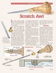
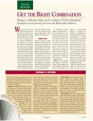
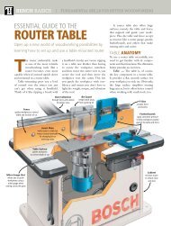
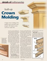
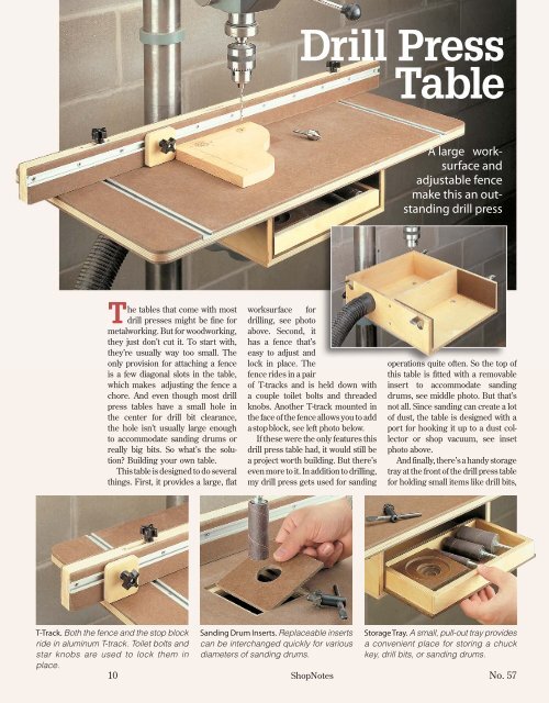
<strong>Drill</strong> <strong>Press</strong><strong>Table</strong>A large worksurfaceandadjustable fencemake this an outstandingdrill pressThe tables that come with mostdrill presses might be fine formetalworking. But for woodworking,they just don’t cut it. To start with,they’re usually way too small. Theonly provision for attaching a fenceis a few diagonal slots in the table,which makes adjusting the fence achore. And even though most drillpress tables have a small hole inthe center for drill bit clearance,the hole isn’t usually large enoughto accommodate sanding drums orreally big bits. So what’s the solution?Building your own table.This table is designed to do severalthings. First, it provides a large, flatworksurface fordrilling, see photoabove. Second, ithas a fence that’seasy to adjust andlock in place. Thefence rides in a pairof T-tracks and is held down witha couple toilet bolts and threadedknobs. Another T-track mounted inthe face of the fence allows you to adda stop block, see left photo below.If these were the only features thisdrill press table had, it would still bea project worth building. But there’seven more to it. In addition to drilling,my drill press gets used for sandingoperations quite often. So the top ofthis table is fitted with a removableinsert to accommodate sandingdrums, see middle photo. But that’snot all. Since sanding can create a lotof dust, the table is designed with aport for hooking it up to a dust collectoror shop vacuum, see insetphoto above.And finally, there’s a handy storagetray at the front of the drill press tablefor holding small items like drill bits,T-Track. Both the fence and the stop blockride in aluminum T-track. Toilet bolts andstar knobs are used to lock them inplace.Sanding Drum Inserts. Replaceable insertscan be interchanged quickly for variousdiameters of sanding drums.Storage Tray. A small, pull-out tray providesa convenient place for storing a chuckkey, drill bits, or sanding drums.10 ShopNotes No. 57
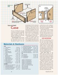
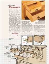
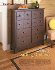
a chuck key, or the sanding insertsmentioned earlier, see right photo.Size – This drill press table issized to fit a 15" Delta drill press. Itshould also work with most other15" (or smaller) drill presses, butyou may have to change the locationof the mounting holes or the openingin the top of the table.BASEIf you take a look at Figure 1, youcan see that this drill press table isreally just a large worksurface thatsits on a shallow plywood box. Thisbox forms the base of the table. Adivider inside the base creates twocompartments — one serves as achamber for dust collection and theother is a storage area to hold thetray that will be added later.To make the base, start by cuttingthe bottom (A) to size from a pieceof 1 / 2" plywood. (I used Baltic birch.)This piece will be fastened to yourdrill press table with carriage boltsand star knobs when the base is finished.To lay out the holes for thebolts, I set the bottom panel on thedrill press table so it was centered23SECOND:TRACE SLOTLOCATIONS ONTOBOTTOMBACKERBOARDSECOND:DRILL !/4"-DIA.THROUGHHOLES1FIRST:FLIP TRACEDSIDE UP AND DRILL1" DIA. x #/16"-DEEP COUNTERBORE1" IN FROM OUTSIDE ENDS OF SLOTSIN THE SHOPCBACK(11#/4" x 3 %/8")5"BSIDE(15" x 3 %/8")CUT HOLE TO FITVACUUM HOOKUPc.FIRST:CENTER BOTTOMON DRILLPRESS TABLEWITH !/8"OVERHANGON BACKBOTTOM#/16"C LMOUNTINGDETAILCDIVIDER(11#/4" x 3 %/8")side to side and overhung the backby 1 / 8". Then working from underneaththe table, trace the location ofthe slotted openings on the bottom,just as you see in Figure 2. Once!/4"-DIA.BITBACKERAMARK SLOTLOCATIONSBASENOTE:ALL PIECESARE !/2"PLYWOODa.!/8"OVERHANGa.SEEDETAIL' b'6"B#6 x1!/4"FhWOOD-SCREWNOTE: TABLE TOPSHOWN ON PAGE 12, FIGURE 4!/4"CARRIAGEBOLT!/4"WASHER!/4"KNOBSEE DETAIL ' a'ABOTTOM(15" x 12 !/2")CA!/8" !/8"A!/8"TOPVIEWC!/2" !/2"these openings are marked out, youcan drill the counterbored holes forthe carriage bolts that will be usedto attach the table (Figure 3). Toprovide clearance for tightening andloosening the star knobs, I locatedthe holes for the carriage bolts aboutan inch away from the ends of theslots in the drill press table.The other parts of the base arealso cut from 1 / 2" plywood. You’llneed two sides (B) and two back/divider pieces (C). After cuttingthese to size, go ahead and cut therabbets and dadoes that are usedto join all the pieces, as shown inFigures 1a and 1b.Dust Collection – Before assemblingthe base, I drilled a large holein one of the sides for a dust collectorhose. Once this is done, the base canbe assembled with glue and a fewwoodscrews. Then to ease the sharpedges, a small roundover is routedon the outer edges (except aroundthe top, which will be covered later).When the base is complete, youcan mount it to your drill press withsome carriage bolts, washers, andstar knobs, see Figures 1 and 1c.Ba.!/2"b.No. 57 ShopNotes 11
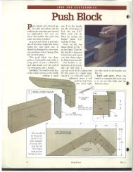
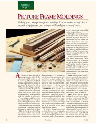
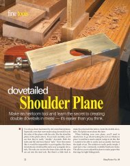
IN THE SHOP{ T-Track Hardware.A toilet bolt, washer,and star knob are allyou need to clampthe fence and stopblock to the T-track.<strong>Table</strong> Assembly ——————————————————————————————With the base completed, you canturn your attention to making thetable assembly. The main purpose ofthe table is to provide a wide, flat surfaceto support your workpiecewhile drilling. In order to get thatflat surface, I decided to sandwicha piece of plywoodbetween two layers of 1 / 4" hardboard,as shown in Figure 4.The plywood provides thestrength, while the hardboardprovides a smooth, longlastingworksurface.To make the top, start by cuttingthe top core (D) to finishedsize from a piece of 1 / 2" plywood.After laying out the roundovers onthe corners, trim each corner witha band saw or sabre saw and sandthe edge smooth. Now you’re readyto laminate the core with the hardboardskins.Instead of trying to match upthe hardboard skins (E) exactlywith the plywood panel, I cut themabout 1 / 2" longer and wider. They’llget trimmed to size later afterthey’re glued to the core.Contact adhesive can be used toattach the skins to the top. And toprevent the pieces from accidentallygetting stuck together while positioningthem, I used some hardwooddowels as spacers, like you see inSKIN417"LONGT-TRACKC L#6 x !/2" FhSHEET METALSCREWNOTE: GLUE HARDBOARDTO PLYWOOD WITHCONTACT ADHESIVE1"DTOP CORE(32" x 17" -!/2" PLYWOOD)5 6a.T-TRACK#6 x !/2" FhSHEET METALSCREWFigure 5. Simply place the dowels ontop of the plywood core. Once youhave the hardboard skin positionedover the plywood, remove thedowels one by one, pressing thehardboard down as you go (Figure5a). After laminating one side of theplywood with hardboard, turn thetop over and laminate the other side.When both skins have been gluedto the plywood core, you can trim theedges of the hardboard flush withINSERT(4!/4" x 4!/4"-!/4" HARDBOARD)#6 x !/2" FhSHEET METALSCREW#6 x !/2"FhSHEETMETAL SCREWESKINS(17" x 32" -!/4" HARDBOARD)MOUNTINGBRACKET#6 x 1!/4"FhSHEET METAL SCREWb.the plywood. A quick way to do thisis with a router and a flush trim bit,as shown in Figure 5b.T-Track Slots – Although thefence for this drill press table won’tbe added until later, now is a goodtime to cut the slots for the aluminumT-track that will be used tomount the fence. As you can see inFigure 6, these slots are cut on thetable saw, using a dado blade. Theslots are sized to hold the aluminumNOTE: TOP/BOTTOMIS SLIGHTLY OVERSIZED(17!/2" x 32 !/2")FENCEDADOBLADEBOTTOM SIDEOF TABLE TOPDOWELSPACERTOP CORESIZEDADOESTO FIT T-TRACK(SEE FIGURE 4 a)REMOVE DOWELS ONE AT ATIME AND PRESSHARDBOARDDOWNa.POSITIONTOP/BOTTOMWITH THEUSE OFDOWELSb.WASTEFLUSHTRIMBIT3#/8" #/4" a.#/8"12 ShopNotes No. 57
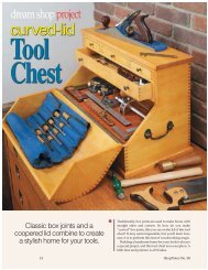
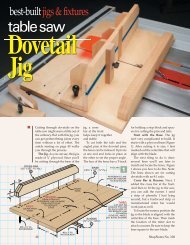
IN THE SHOP7 8C L4!/4" 4!/4"SECOND:LOCATE QUILL CENTERAND LAY OUT INSERTLOCATION ONTO TABLE TOPCARPET TAPEHARDBOARD STRIPSAROUND OPENINGTO SERVE ASTEMPLATENOTE:ROUTER BODYREMOVEDFOR CLARITYFIRST:CENTER TABLE TOP WITHCENTER OF COLUMNFOURTH: CUTOUT WASTE WITHSABRE SAWTHIRD:DRILL STARTERHOLES #/8" IN FROM EACH CORNERa.a.GUIDEBUSHINGSTRAIGHTBITWASTESEEARTPOSITION STRIPSACCORDING TODISTANCE FROMBUSHING EDGE TOBIT EDGE (SEE DETAIL)T-track. After making the slots, theT-track can be cut to length andscrewed in place. Shop Note: The T-track can be cut on the table sawwith a carbide-tipped saw blade.Insert Opening – The last step tocompleting the top is to make theopening for the sanding drum insertplates. This opening is recessed tocreate a ledge for holding a replaceableinsert plate.9SANDINGDRUMa.BASESANDINGDRUMCUT INSERT TOFIT 4!/4" x 4!/4"OPENINGNOTE:DRILL HOLE!/4" TO !/2"LARGERTHAN DRUMDIAMETERINSERTPLATEINSERTTo locate the opening on the top,center the top on the base and chuckup a drill bit to mark the center of theopening on the top, as you see inFigure 7. After laying out theopening around this centerpoint,drill a hole in each corner of theopening area, 3 / 8" in from the edge.Then cut out the waste between theholes with a sabre saw (Figure 7a).To create the ledge for the insert10WINGCUTTERa.WASTEHANDSCREWCLAMP INSERTBLANK IN HANDSCREW TO DRILLHOLEINSERTBACKER BOARDplate to rest on, I used a router alongwith a straight bit and guidebushing. Scraps of hardboard aretaped down around the opening toserve as a template. Then the ledgeis routed (Figure 8). The router bitcan’t reach all the way into the cornersof the opening. So you’ll have tocome back with a chisel to squarethem up. Once this is done, the topcan be screwed to the base using themounting brackets that are shown inFigures 4 and 4b.Insert Plates – The insert platesare nothing more than square piecesof 1 / 4" hardboard cut to fit in theopening in the top. For drilling, Imade up several blank inserts with asmall fingerhole for easy removal.This way I have replacements onhand as they get chewed up. Thenfor my sanding drums, I made anassortment of inserts with varioussizes of holes, see photo.A wing cutter works well fordrilling the larger holes in theinserts. The trick is holding onto theinsert safely while drilling the hole.Here’s where a wooden hand screwclamped to your drill press comes inhandy, as you can see in Figure 10. Abacker board cut to the same size asthe insert prevents tearout.{ Hardboard Inserts.You can customizethe sizes of theopenings in theinserts to match yoursanding drums.No. 57 ShopNotes 13
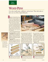
IN THE SHOP{ Fence. Looseninga couple ofknobs allows you toadjust the fencequickly or remove itentirely.Fence & Stop ————————————————————————————————The last parts to addto the top of the drillpress table are thefence and sliding stopblock. These twoitems work together.The fence rides in theT-track that ismounted in the top ofthe table, and the stopblock rides in a separateT-track that is mounted in thefront face of the fence (Figure 11).The fence is made up of two layersof 1 / 2" plywood that are sandwichedbetween two layers of 1 / 4" hardboard.This creates a fence that is thickenough and strong enough to resistflexing or bowing in use. But there’sanother reason for this laminatedconstruction. It allows you to createa pair of slots in the fence for themounting bolts without having to doany drilling or mortising. I’ll explainthis in a little more detail later.The fence blank (F) starts out asa 6"-wide piece of 1 / 2" plywood. AFIRST: CUTDADOES INBLANKWASTE!/8"ROUND-OVER36"-LONGT-TRACK2"!/8"4#/4" 36"SECOND:RIP BLANK INTOTWO FENCE HALVES#6 x !/2"FhSHEETMETALSCREW1112 1314!/4"WASHERNOTE:!/8" ROUND-OVER ON ALLEDGES OF FENCE& STOP!/4"KNOBNOTE: WAX KEYSBEFORE GLUINGFENCETOGETHERWORKBENCH!/4" x 3!/2"TOILETBOLTlayer of 1 / 4" hardboard is glued tothis plywood and then trimmedflush, just like you did when makingthe top of the drill press table.To create the slots in the fence, apair of dadoes are cut across the faceof the fence blank, as shown inFigure 12. (These are cut on the plywoodside of the blank.) Once this isTABLESAWFENCESIZE GROOVE TOFIT T-TRACK!/2" #/4"#/8"WAXPAPERa.FENCE2!/2"STOP BLOCK(SEE FIG. 15)FENCEEND VIEW36"LONGT-TRACKSTOPBLOCKT-TRACKSa.done, a pair of 2 1 / 2"-wide strips areripped from the blank. These will bethe two halves of the fence.Keys – The next step is to gluethe two strips together to create thefence. The trick here is to keep thedadoes in the strips perfectlyaligned during the glue-up process.To help with this, I cut a couple of“keys” out of some scrap wood tofit in the dadoes, as shown inFigure 13. These keys keep thepieces aligned while the glue dries.And to prevent the keys from accidentallybecoming glued in place, Irubbed them thoroughly with waxbefore inserting them.After the glue has dried, you cancut a groove in one face of the fencefor the T-track. This is cut with adado blade, just like you cut the slotsin the table (Figures 14 and 14a).Before screwing the T-track in place,I routed a 1 / 8" roundover on all theedges and corners of the fence. Thefence is then mounted to the tablewith a couple of toilet bolts, washers,and plastic knobs (Figure 11).Stop Block – The stop block (G)couldn’t be much simpler. It’s just ablock of 1 / 2" plywood with a 5 / 16"-diameter hole in it. The hole is for a14 ShopNotes No. 57
IN THE SHOPtoilet bolt that is used to attach thestop block to the fence, just like yousee in Figure 15. Like the fence, theedges and corners of the stop blockare slightly rounded over. But thistime, I just used a sanding block tomake the roundovers. It’s a lot easier(and safer) than trying to rout themon such a small workpiece.Before mounting the stop block,there’s just one more detail to takecare of. Using a hack saw, I cut downthe toilet bolt used to mount the stopblock, so the bolt wouldn’t stick outof the knob too far. Now just add awasher and star knob and you’re finished,except for the storage tray.15NOTE: CUT !/4" 3!/2"TOILETBOLT TO 1!/2"x LONGDRILL%/16"-DIA.HOLE&/8"!/4"WASHER2!/2"STOP a.!/4"BLOCKKNOBC L2!/2"GSTOP BLOCK(!/2"PLYWOOD){ Stop Block. Anadjustable stopblock comes inhandy for drillingidentical holes inmultiple pieces.Storage Tray ————————————————————————————————TOILETBOLTThe storage tray is really anoptional part of the drill press table.You don’t need to build it if youdon’t want to. But I found it to bethe perfect place for storing thestop block and sanding inserts, aswell as a chuck key or a few drillbits. This tray slides into the frontof the base of the drill press table.To make the tray, start by cuttinga piece of 1 / 4" hardboard to sizefor the tray bottom (H). The sidesof the tray are just 1 / 2" plywoodglued to the top of the tray bottom,as shown in Figure 16. You’ll needtwo identical pieces for the tray166"3#/8"!/4"KTRAY GUIDEHBOTTOMNOTE:(11&/16"x 6" -!/4" LIP REMAINS!/4" HARDBOARD)AT EACH ENDAFTER GLUE-UP(SEE DETAILS ' a' AND ' b')Kfront and back (I), as well as a pairof tray ends (J). When cuttingthese pieces, note that the trayfront and back are 1 / 2" shorter thanthe width of the tray bottom. Thisis to create a lip on each side of thetray which will slide into a couple ofguides in the base.The front and back pieces are rabbetedto hold the tray ends (Figure16a). After these rabbets are cut, thefront, back, and ends can be gluedtogether and then to the bottom ofthe tray. Once the glue is dry, youcan round over the edges of the trayslightly with some sandpaper.IFRONT(!/2"PLYWOOD)END(!/2"PLYWOOD)JNOTE: TABLE TOPREMOVED FORCLARITY5!/2"10!%/16"1!/4"Tray Guides – Thetray slides in groovesin the base of the drillpress table. Thesegroovesarecreatedbyadding a pair of hardboardtray guides (K)to the inside walls ofthe tray compartment,see Figure 16b. These are cut 1 / 4"shorter than the height of the compartment.This way, when they areglued in place flush with the top edgeof the sides of the base, they create agroove on each side of the compartmentfor the tray to slide in.1!/4"a.!/4"Jb.BASE!/2"TOP VIEW(TRAY ONLY)LIP!/4"FRONT VIEWTRAY GUIDEITRAYBOTTOM{ Storage Tray. Ashallow tray slidesneatly into the baseof the drill presstable.No. 57 ShopNotes 15