Faac City 275_Aut_ H600_H800_RevC_GB.pdf
Faac City 275_Aut_ H600_H800_RevC_GB.pdf
Faac City 275_Aut_ H600_H800_RevC_GB.pdf
- No tags were found...

Create successful ePaper yourself
Turn your PDF publications into a flip-book with our unique Google optimized e-Paper software.
<strong>Aut</strong>omatic hidden traffic bollards<strong>275</strong> <strong>H600</strong> and <strong>275</strong> <strong>H800</strong>with pitFAAC S.p.A. Via Benini, 1 40069 Zola Predosa Bologna (Italia) tel. +39 051 61724 www.faac.it- 0 -
Technical installation manual‣ CE Declaration of conformity‣ Warnings for the installer‣ Technical specifications of the traffic bollard‣ Preparing and installing the traffic bollard‣ Wiring diagram of the traffic bollard with 624 BLDcontrol unit‣ Programming the 624 BLD unit‣ Technical specifications of the <strong>Faac</strong> <strong>City</strong> MASTERcontrol station‣ Diagrams of the MASTER control station‣ Dip-Switches of the MASTER control board‣ Terminal boards connecting MASTER and SLAVEcontrol boards‣ Manual lowering procedure‣ Maintenance operationsFAAC S.p.A. Via Benini, 1 40069 Zola Predosa Bologna (Italia) tel. +39 051 61724 www.faac.it- 1 -
CE DECLARATION OF CONFORMITY FOR MACHINES(DIRECTIVE 98/37/EC)Manufacturer: FAAC S.p.A.Address:Declares that:Via Benini, 1 - 40069 Zola Predosa BOLOGNA - ITALYthe operator mod. FAAC CITY <strong>275</strong> <strong>H600</strong> and <strong>275</strong> <strong>H800</strong> AUTOMATIC• is built to be integrated into a machine or to be assembled with other machinery to create a machineunder the provisions of Directive 98/37/EC;• conforms to the essential safety requirements of the following EEC directives:73/23/EEC and subsequent amendment 93/68/EEC.89/336/EEC and subsequent amendment 92/31/EEC and 93/68/EECand also declares that it is prohibited to put into service the machinery until the machine in which it willbe integrated or of which it will become a component has been identified and declared asconforming to the conditions of Directive 98/37/EC.Bologna, 01 January 2007The Managing DirectorA. BassiCE DECLARATION OF CONFORMITYManufacturer: FAAC S.p.A.Address:Declares that:Via Benini, 1 - 40069 Zola Predosa BOLOGNA - ITALYthe equipment <strong>Faac</strong> <strong>City</strong> Master, <strong>Faac</strong> <strong>City</strong> Slave and 624 BLD• conform to the essential safety requirements of the following EEC directives:73/23/EEC and subsequent amendment 93/68/EEC.89/336/EEC and subsequent amendment 92/31/EEC and 93/68/EECAdditional note:These products underwent tests in a typical uniform configuration(all products manufactured by FAAC S.p.A.)Bologna, 01 January 2007The Managing DirectorA. BassiFAAC S.p.A. Via Benini, 1 40069 Zola Predosa Bologna (Italia) tel. +39 051 61724 www.faac.it- 2 -
WARNINGS FOR THE INSTALLER – GENERAL SAFETY OBLIGATIONS1 ATTENTION! To ensure the safety of people, it isimportant that you read all the following instructions.Incorrect installation or incorrect use of the productcould cause serious harm to people.2 Carefully read the instructions before beginning toinstall the product.3 Do not leave packing materials (plastic, polystyrene,etc.) within reach of children as such materials arepotential sources of danger.14 Make sure that the earthing system is perfectlyconstructed, and connect metal parts to it.15 The automated system is supplied with an intrinsicanti-crushing safety device consisting of a torquecontrol. Nevertheless, its tripping threshold must bechecked as specified in the Standards indicated atpoint 10.16 The safety devices (EN 12978 standard) protect anydanger areas against mechanical movement Risks,such as crushing, dragging, and shearing.4 Store these instructions for future reference. 17 Use of at least one indicator-light is recommendedfor every system (i.e. flashing lamp integrated in thebollard head), as well as a warning sign in additionto the devices mentioned at point “16”.5 This product was designed and built strictly for theuse indicated in this documentation. Any other use,not expressly indicated here, could compromise thegood condition/operation of the product and/or bea source of danger.18 For maintenance, strictly use original parts by FAACS.p.A.6 FAAC S.p.A. declines all liability caused by improperuse or use other than that for which the automatedsystem was intended.7 Do not install the equipment in an explosiveatmosphere: the presence of inflammable gas orfumes is a serious danger to safety.8 For non-EU countries, to obtain an adequate level ofsafety, the Standards mentioned above must beobserved, in addition to national legal regulations.9 FAAC S.p.A. is not responsible for failure to observeGood Technique in the installation of the FAAC CITYproducts and relating accessories or for anydeformation that may occur during use.10 Installation must be performed in compliance withthe currently Ruling Standards.11 Before attempting any job on the system, cut outelectrical power .12 The mains power supply of the automated systemmust be fitted with an all-pole switch with contactopening distance of 3mm or greater. Use of adifferential 6A thermal breaker with all-pole circuitbreak is recommended.13 Make sure that a differential switch with threshold of0.03 A is fitted upstream of the system.19 FAAC S.p.A. declines all liability as concerns safetyand efficient operation of the automated system, ifsystem components not produced by FAAC S.p.A.are used.20 Do not in any way modify the components of theFAAC CITY automated system.21 The installer shall supply all information concerningmanual lowering of the bollard in case of anemergency, and shall hand over to the user thewarnings handbook supplied with the product.22 Do not allow children or adults to stay near thebollard while it is operating.23 Keep radio controls or other pulse generators awayfrom children, to prevent the automated system frombeing activated involuntarily.24 Transit on the FAAC CITY traffic bollard is permittedonly when the automated system is idle25 The user must not attempt any kind of repair or directaction whatever and contact qualified personnelonly.26 Anything not expressly specified in these instructionsis not permittedFAAC S.p.A. Via Benini, 1 40069 Zola Predosa Bologna (Italia) tel. +39 051 61724 www.faac.it- 3 -
TECHNICAL SPECIFICATIONS OF FAAC CITY <strong>275</strong> <strong>H600</strong> AND <strong>275</strong> <strong>H800</strong>Driving methodHydraulicDriven cylinderFE37 steel * 1 – thickness 6 mmDriven cylinder treatment Polyester powder paint, dark greycolour, metalised * 2Driven cylinder diameter<strong>275</strong> mmDriven cylinder stroke 600 mm (<strong>275</strong> <strong>H600</strong>) and 800 mm. (<strong>275</strong><strong>H800</strong>)Cylinder top part (head)Anticorodal case hardened aluminiumCylinder surface treatment Polyester powder paint, light greycolour, metallisedDescent time 5 sec. (<strong>275</strong> <strong>H600</strong>) – 7 sec. (<strong>275</strong> <strong>H800</strong>)Rise time 5 sec. (<strong>275</strong> <strong>H600</strong>) – 7 sec. (<strong>275</strong> <strong>H800</strong>)Hydraulic pumpPower supply 230V +6/-10% 50HzProtection class IP 67Pump capacitor16 μFAbsorbed powerWork frequencyReflecting adhesive strip220WHeavy dutyStandard height 55 mmOperating ambient temperature - 40°C + 70°C * 3Total weight with pit Kg. 180 - 200Manual lowering operation Yes * 4Impact resistance 15,000 joule (FE37 steel – thickness 6mm.)Dimensions of pit to be walled in 560 x 560 x 1020 (<strong>275</strong> <strong>H600</strong>)560 x 560 x 1220 (<strong>275</strong> <strong>H800</strong>)Standard length with connected cable 10 m * 5Heating Elements24 Volts, 80 Watts* 1 optional item: FE37 steel thickness 10 mm or stainless steel AISI 304 thickness 6mm.* 2 optional item: customised spray painting in RAL range* 3 optional item: heating resistances (recommended for temperatures less than–15°C to limit cylinder icing)* 4 optional item: automatic lowering device in the event of power fault* 5 optional item: length up to 30 m available on order.FAAC S.p.A. Via Benini, 1 40069 Zola Predosa Bologna (Italia) tel. +39 051 61724 www.faac.it- 4 -
AUTOMATIC TRAFFIC BOLLARDS WITH PITFAAC CITY <strong>275</strong> <strong>H600</strong> and <strong>275</strong> <strong>H800</strong>INSTALLATION DIAGRAM1) Make sure that the place where the FAAC CITY traffic bollard is to be installed is not a cavity; ifthis situation is present, partially protect the FAAC CITY traffic bollard with a drainage channelequipped with covering grid.2) Dig up to a depth of about 1.30 m (<strong>275</strong> <strong>H600</strong>) or about 1.50 m (<strong>275</strong> <strong>H800</strong>); the cross-section shallhave a side of about 1 m (fig. 1 and fig. 2).3) Make sure that the ground is able to absorb water: pour about 40 l water in the dig and check ifdraining takes place within 30 minutes. If this is not the case, discharge rainwater by means of apipeline with a diameter of 60mm connected to the drainage system or, as an alternative,connected to a pit equipped with a drainage system (i.e. motor pump), having a depth greaterthan the FAAC CITY pit for the collection and drainage of rainwater.4) Introduce gravel (grain with a diameter of approx. 8 - 20 mm) to obtain a thickness of about 30cm, taking care to compact it well to avoid future settlements.5) Install the metallic pit complete with counter-frame, taking care to position it vertical. The toplevel of the counter-frame must be approx. 10mm higher than the floor surface (to limit the inletof rainwater in the pit). Place the pit checking the reference of the counter-frame according tothe sense of direction (fig. 1 and fig. 2).6) After pit installation, lay a flexible sheath, internal diameter 45mm, from the electricalconnection in the pit to the drive control station.7) Cast concrete all around the pit, up to approx. 10cm from the floor surface, and make sure thatthe anchors supplied with the pit are correctly positioned. Once the pit has been positioned,finish the street surface using the same type of material (fig. 3 and fig. 4).8) Lay the necessary pipes for the connection between the control unit and any additional device(i.e. traffic lights – inductive loops – card reader – etc.) and every other bollard, if present. Thenprepare the electrical connection and the earthing (fig. 5).N.B.: every pipe must be laid in compliance with the current rules.FAAC S.p.A. Via Benini, 1 40069 Zola Predosa Bologna (Italia) tel. +39 051 61724 www.faac.it- 5 -
POSITIONING THE FAAC CITY <strong>275</strong> <strong>H600</strong>Fig. 1FAAC S.p.A. Via Benini, 1 40069 Zola Predosa Bologna (Italia) tel. +39 051 61724 www.faac.it- 6 -
Fig. 2FAAC S.p.A. Via Benini, 1 40069 Zola Predosa Bologna (Italia) tel. +39 051 61724 www.faac.it- 7 -
POSITIONING THE FAAC CITY <strong>275</strong> <strong>H800</strong>Fig. 3FAAC S.p.A. Via Benini, 1 40069 Zola Predosa Bologna (Italia) tel. +39 051 61724 www.faac.it- 8 -
Fig. 4FAAC S.p.A. Via Benini, 1 40069 Zola Predosa Bologna (Italia) tel. +39 051 61724 www.faac.it- 9 -
ALIGNING SEVERAL FAAC CITY DEVICESFig. 5FAAC S.p.A. Via Benini, 1 40069 Zola Predosa Bologna (Italia) tel. +39 051 61724 www.faac.it- 10 -
POSITIONING THE SAFETY INDUCTIVE LOOPSAny inductive loops making part of the system must be laid in compliance with the instruction of the detector.Two laying examples are given in the figures below.Fig. 6 represents the installation of a single bollard with two magnetic loops for the detection of the vehicletransit.Fig. 7 represents the laying of a loop to obtain the external protection of the bollard.Fig. 8 represents the laying of two loops protecting a passage with large dimensions.INSTALLATION DIAGRAM FOR 1 FAAC CITY K <strong>275</strong> <strong>H600</strong> AND <strong>H800</strong>Fig. 6FAAC S.p.A. Via Benini, 1 40069 Zola Predosa Bologna (Italia) tel. +39 051 61724 www.faac.it- 11 -
Fig. 7Fig. 8FAAC S.p.A. Via Benini, 1 40069 Zola Predosa Bologna (Italia) tel. +39 051 61724 www.faac.it- 12 -
PIPE LAYING DIAGRAM FOR 1 FAAC CITY K <strong>275</strong> <strong>H600</strong> AND <strong>H800</strong>Fig. 9FAAC S.p.A. Via Benini, 1 40069 Zola Predosa Bologna (Italia) tel. +39 051 61724 www.faac.it- 13 -
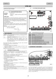
PIT – 624 BLD UNIT CONNECTION DIAGRAMFig. 10NOTE: During the first 4 seconds of the <strong>Faac</strong> <strong>City</strong> rise, the pressure switch behaves as a safety photocell. Therefore refer tocolumn FSW in the Logic tables to check its behaviour in the different functions.FAAC S.p.A. Via Benini, 1 40069 Zola Predosa Bologna (Italia) tel. +39 051 61724 www.faac.it- 14 -
CONNECTION WITH 624 BLD UNITTo control the <strong>Faac</strong> <strong>City</strong> device with the 624 BLD unit, you need to connect the internal components ofthe traffic bollard according to the diagram of fig. 10 (if necessary, use the connection diagram indicatedin the electronic manual of the 624 BLD unit for a more complete overview of the connections):Specifically, connect the cables coming from the safety pressure switch to the terminal board ofthe travel-limit adapter, as shown in the following figure:Fig. 11Grey = Pressure SwitchGrey = Pressure SwitchThe absence of the opening travel-limit device in the <strong>Faac</strong> <strong>City</strong> application requires you to shortcircuitthe J3 connector as shown in figure 11.Take great care when connecting the automatic lowering solenoid valve, if present. This solenoidvalve, in fact, must be supplied with 24 Volt DC via an EXTERNAL POWER UNIT 230Vac-24Vdc ableto supply 1.3 amp connected to the FAN output of the 624 BLD board on terminals 22 and 23 (asshown in fig. 10).The heating resistances (optional item), if any, shall be controlled via an external power unit and athermostat, which are independent from the 624 BLD board.PROGRAMMING THE BOARDYou need to change the following programming step on the 624 BLD board (refer to chapter“PROGRAMMING” of the electronic manual of the 624 BLD board):First programming step- Set the step d F to the value 03 to install the FAAC CITY <strong>H600</strong> and <strong>H800</strong> standard. Exit the firstprogramming level by scrolling the steps with the “F” key until you reach the status of theapplication without making any further changes.The a.m. operation is indispensable and must always be carried out at the beginning of a newinstallation, BEFORE changing any other parameters in order to customise the application.In this way, you can set the following basic parameters to control the <strong>Faac</strong> <strong>City</strong> on the 624 BLDboard:Logic A, Pause time 30 seconds, Work Time Out 12 seconds, OUT1 output for Buzzer, OUT2 output forHead Lights and control parameters of the travel-limit/safety pressure switch.To customise the operation of the <strong>Faac</strong> <strong>City</strong> you can now enter the first and second programminglevel, remembering however not to change the parameter d F that shall remain to 00.Further details and customisations can be found in the electronic manual of the 624 BLD board,which is supplied together with the application.FAAC S.p.A. Via Benini, 1 40069 Zola Predosa Bologna (Italia) tel. +39 051 61724 www.faac.it- 15 -
TECHNICAL SPECIFICATIONS OF THE FAAC CITY MASTER CONTROLSTATIONElectronic control circuitWith microprocessor with specific softwarefor controlling the FAAC CITY traffic bollardsHousing for control stationStandard, wall-mountedDimensions of housingsee enclosed tableProtection class IP 55Operating ambient temperature -15°C + 70°CControl station power supply230V. +6/-10% - 50HzProtective switches Thermal-magnetic 1P + N – 6A ÷ 16A – 30mA -6KAService transformer230/24 Vac 100VAMax. quantity of <strong>Faac</strong> <strong>City</strong>s that can be Max 10 FAAC CITY devices with simultaneousconnected to the control station movement – the first FAAC CITY is connectedto the master unit – the remaining devices areconnected to the additional slave units – thehousing dimension depends on the quantityof FAAC CITY and on the requiredaccessoriesHOUSINGS FOR FAAC CITY TRAFFIC BOLLARDSDRIVE CONTROL STATIONSDimensionsL x H x DMaterialSystem configurationPLAST 120° C - For basic system with 1 FAAC CITY.WALL-MOUNTED HOUSING320 X 400 X 160WALL-MOUNTED HOUSING400 X 480 X 160WALL-MOUNTED HOUSING400 X 600 X 200WALL-MOUNTED HOUSING500 X 700 X 200FLOOR COLUMN320 X 950 X 280Protection class IP 44PLAST 120° CSTEEL FE 37STEEL FE 37POLYESTER- For system with accessories and 1 FAAC CITY.- For basic system with 2 FAAC CITY.- For system with accessories and 2 FAAC CITY.- For basic system with 3 FAAC CITY.- For system with accessories and 5 FAAC CITY.- For basic system with 8 FAAC CITY.- For system with accessories and 2 FAAC CITY.- For basic system with 3 FAAC CITY.‣ LARGER DIMENSIONS ARE AVAILABLE ACCORDING TO THE SYSTEM CONFIGURATIONFAAC S.p.A. Via Benini, 1 40069 Zola Predosa Bologna (Italia) tel. +39 051 61724 www.faac.it- 16 -
LAYOUT OF FAAC CITY MASTER AND FAAC CITY SLAVE EQUIPMENTBelow you will find the layouts of the Master and Slave equipment with the signalling LEDs functionsand the indications of the protective fuses.L1L1 -– Input Input Pressostato Pressure SwitchL2L2-–InputInputFCforAperturaopening Limit SwtchL3 – Output for BuzzerL3 - Out Segnalatore acusticoL4 – Output for signalsL4 - Out Segnalazione (mobile)L5 – Output for signalsL5 L6-–OutOutputSegnalazionefor closure(fisso)(rise)L6 L7 -– Out Output in Chiusura for solenoid (sollevame valve nto)L7 L8 -– Out Output Elettrovalvola for openingL8 L9 -– Output In Apertura for movement (abbassamento)L9 L10 - Out – Output Movimento for green traffic lightL10 L11 - Out – Output Semaforo +12 Vdc VerdeL11 L12 - (Out) – Output + 12V +24 c.c. Vdc OKL12 L13 - (Out) – Input + 24V START c.c. OKL13 L14 - Input – Input Start for Magnetic LoopL14 - Input Spira di sicurezzaOperating TASTO DI KeyAZIONAMENTOPF1 – Transformer ProtectionPF1 PF2 -– Protezione Clock Protection TrasformatorePF2 PF3 -– Protezione Traffic Light Orologio ProtectionPF3 PF4 -– Protezione Solenoid Valve Semaforo ProtectionPF4 PF5 -– Protezione Auxiliary Protection ElettrovalvolaPF5 PF6 -– Protezione 24Vdc Protection AusiliariaPF6 PF7 -– Protezione Logic Protection Ausiliaria 24VPF7 - Protezione LogicaApparecchiatura MASTER CONTROL Master UNIT - Layout COMPONENTS e componentiFAAC S.p.A. Via Benini, 1 40069 Zola Predosa Bologna (Italia) tel. +39 051 61724 www.faac.it- 17 -
Connettore Connector collegamentobetweenMaster Master/Slave & SlaveSlave/SlaveL1 – Input - Input for pressure Pressostato switchL2 – Input - Input for opening Finecorsa limit switch AperturaL3 – 24 VdcL3 - (Out) + 24V c.c. OKPF1 – Auxiliary protectionPF1 PF2 – Transformer - Protezione protection AusiliariaPF2 - Protezione TrasformatoreConnettore Connector collegamento betweenSlave/Slave & Apparecchiatura SLAVE CONTROL Slave UNIT - Layout COMPONENTS e componentiFAAC S.p.A. Via Benini, 1 40069 Zola Predosa Bologna (Italia) tel. +39 051 61724 www.faac.it- 18 -
POWER SUPPLY FOR THE FAAC CITY MASTER AND FAAC CITY SLAVE EQUIPMENTBelow you will find the diagrams for connecting the power supply to the Master boardand to the Master board with one or more cascade-connected Slave boards.Usually the transformers are connected in the factory.Note: the <strong>Faac</strong> <strong>City</strong> devices connected to the Slave boards perform the same movementas that connected to the Master board. If you need the bollards to perform differentmovements, you shall fit a Master board for every movement type to control.Linea Power 230VC6Id 30mA230V545355 56 57 58 59230VPOWER52511ATSTOP50492AT2ATPredisposizione N.C.Pulsante sgancio di emergenzaCOM NO NC48474645230VG44Trasformatore100 VA230 VR4342230VG41R4024 V 16 V 0 V230V 12V 0 12VA B C0V +12 +2424~393837363534333231302928272625242322212AT 5AT 1AT 2AT12345678910111213141516171819MA B CCOM++ + +PRCollegamento <strong>Faac</strong> <strong>City</strong>20Predisposizione N.C.Rilevatore induttivo OpzionaleSTARTAUTINLOOPPR1PR21 2 3 45ApMASTER parecchiatura CONTROL Master UNIT - AlimentazioneCOMPONENTSFAAC S.p.A. Via Benini, 1 40069 Zola Predosa Bologna (Italia) tel. +39 051 61724 www.faac.it- 19 -
RRB123PRBPR230V545355 56 57 58 59C10PowerLinea 230VId 30mAPredisposizione N.C.Pulsante sgancio di emergenzaTrasformatore100 VA230 V24 V 16 V 0 V230VPOWERSTOP230V230VCOM NO NC230V12V 012VAC0V +12+2424~GG52515049484746454443424140393837363534333231302928272625242322211AT 2AT2AT 5AT 1AT 2AT2AT12345678910111213141516171819MA B CCOM++ + +Collegamento <strong>Faac</strong> <strong>City</strong> 120STARTPredisposizione N.C.Rilevatore induttivo OpzionaleAUTINLOOPPR1PR24 5A B C230V12V 012V28272625242322212019185AT2ATL3L1L21234567891011121314151617AMCCOM++ +Collegamento <strong>Faac</strong> <strong>City</strong> 2AMASTER pparecchiature & SLAVE Master CONTROL e Slave UNIT - AlimentazioneCONNECTIONSFAAC S.p.A. Via Benini, 1 40069 Zola Predosa Bologna (Italia) tel. +39 051 61724 www.faac.it- 20 -
RRABCABC123C+PRABC++++PRPR230V545355 56 57 58 59C10Linea Power 230VId 30mAPredisposizione N.C.Pulsante sgancio di emergenzaTrasformatore230 V100 VA24 V 16 V 0 V230VPOWERSTOP230V230VCOM NO NC230V12V 012V0V +12+2424~GG52515049484746454443424140393837363534333231302928272625242322211AT 2AT2AT 5AT 1AT 2AT2AT12345678910111213141516171819A BCOM+ + +MCollegamento <strong>Faac</strong> <strong>City</strong>120STARTAUTPredisposizione N.C.Rilevatore induttivo OpzionaleINLOOPPR1PR24 5A B C230V12V 012V28272625242322212019185AT2ATL3L1L21234567891011121314151617+ +MCOMCollegamento <strong>Faac</strong> <strong>City</strong> 2230V12V0 12V28272625242322212019185AT2ATL3L1L21234567891011121314151617A B CMCOMCollegamento <strong>Faac</strong> <strong>City</strong> 3Apparecchiature MASTER & 2 SLAVE Master CONTROL e 2 Slave UNIT - AlimentazioneCONNECTIONSFAAC S.p.A. Via Benini, 1 40069 Zola Predosa Bologna (Italia) tel. +39 051 61724 www.faac.it- 21 -
TERMINAL BOARD CONNECTING THE MASTER BOARD1-2-3 = through connection with 33-32-31 with protective fuse4-5-6-7-8 = connection of the hydraulic unit9-10 = connection of the automatic lowering device in the event of a 230Vpower fault11-12 = connection of the safety pressure switch13 = common contact for limit switch– buzzer– flashing lamp14 = connection for FAAC CITY limit switch down15 = connection for intermittent buzzer FAAC CITY16 = connection of the flashing lamp incorporated in the FAAC CITYhead17 = common contact for: limit switch-buzzer–flashing lamp18-19 = connection of flashing luminous sign (24 V a.c. intermittent output)20-21-22-23 = connection of the safety inductive detector24-25 = input for lowering control26-27-28-29-30 = connection of the lowering control device31-32-33 = through connection with 3-2-1 with protective fuse34-35-36-37-38-39 = connection of service transformer40-41-42 = 230v connection traffic light 143-44-45 = 230v connection traffic light 246-47-48 = traffic light remote repetition (voltage-free contact)49-50 = connection of the emergency lowering push-button51-52 = 230v connection to the electronic circuit53 = not used54 = earthing connection55-56-57-58-59 = connection of the weekly/yearly clockTERMINAL BOARD CONNECTING THE SLAVE BOARD1-2-3 = through connection with 28-27-26 with protective fuse4-5-6-7-8 = connection of the hydraulic unit9-10 = connection of the automatic lowering device in the event of a 230vpower fault11-12 = connection of the safety pressure switch13 = common contact for limit switch – buzzer – flashing lamp FAAC CITY14 = connection for limit switch FAAC CITY down15 = connection for intermittent buzzer FAAC CITY16 = connection of flashing lamp incorporated in the FAAC CITY head17 = common contact for limit switch – buzzer – flashing lamp FAAC CITY18-19-20 = connection to the service transformer21 = not used22-23 = 230v connection to the electronic circuit24 = not used25 = earthing connection26-27-28 = through connection with 3-2-1 (with protective fuse)FAAC S.p.A. Via Benini, 1 40069 Zola Predosa Bologna (Italia) tel. +39 051 61724 www.faac.it- 22 -
FUNCTIONS OF THE DIP–SWITCHES OFFAAC CITY MASTER BOARDThe dip-switch no. 1 on the <strong>Faac</strong> <strong>City</strong> Master board enables you to select the operatinglogic of the system (automatic or semiautomatic).The dip-switches no. 2, 3 and 4 have been added to simplify trouble-shooting operationsduring system repair/maintenance jobs.In facts, if faults occur, you do not need to disconnect the wires from the terminal boards,but you can override part of the circuits by positioning the dip-switches as you require.DIP – SWITCH “OFF” No. DS DIP – SWITCH “ON”AUTOMATIC RISE ENABLED 1 AUTOMATIC RISE DISABLEDCOMMANDS ENABLED 2 COMMANDS DISABLEDSAFETY DEVICES ENABLED 3 SAFETY DEVICES DISABLEDRISE TRAVEL-LIMIT PRESSURE SWITCHENABLED4 RISE TRAVEL-LIMIT PRESSURE SWITCHDISABLED_ _ _ _ _ _ _ _ _ _ _ _ _ _ _ _ _ _ _5 LEAVE ALWAYS ONDIP – SWITCH 1This position is to be defined according to the use and the system configuration (if nosafety device is used, it MUST be positioned to ON)‣ OFF position = AUTOMATIC RISE ENABLED: the traffic bollard, normally in up position,moves to down position following a command. After the vehicle has transited throughthe controlled passage (and therefore it engages and then disengages the safetydevices) the traffic bollard goes up again. If the vehicle does not pass, the trafficbollard returns automatically to the up position after 30”. If the opening command iskept pressed, the traffic bollard remains in down position until the command isreleased (timer function).‣ ON position = AUTOMATIC RISE DISABLED: the traffic bollard, after a first command,moves from up to down position. Following a further command it returns up.Default position: OFFDIP – SWITCH 2‣ OFF position = COMMANDS ENABLED: the commands for the bollard movement,connected to terminals 24/25 – 26/27 – 58/59, are in function.‣ ON position = COMMANDS DISABLED: the commands for the bollard movement,connected to terminals 24/25 – 26/27 – 58/59, are disabled. If the FAAC CITY trafficbollard does not rise, run a test by means of the push-button on the board (START) afterhaving momentarily disabled the external command devices.FAAC S.p.A. Via Benini, 1 40069 Zola Predosa Bologna (Italia) tel. +39 051 61724 www.faac.it- 23 -
Default position: OFFDIP – SWITCH 3:‣ OFF position = SAFETY DEVICES ENABLED: the inputs for the safety devices (terminals20/21) are enabled. If no safety devices are fitted, jumper connect terminals 20 and21.‣ ON position = SAFETY DEVICES DISABLED: the input for the safety devices (terminals20/21) is disabled. If the FAAC CITY traffic bollard does not rise, you can momentarilydisable the safety devices to check if the fault is caused by them.Note: to fit devices for the detection of metallic masses, please refer to the instructions ofthe traffic bollard and to the instructions of the single devices.Default position: OFFDIP – SWITCH 4:‣ OFF position = RISE TRAVEL-LIMIT PRESSURE SWITCH ENABLED: in the final rising phase, thesignal from the pressure switch is used as rise travel-limit.‣ ON position = RISE TRAVEL-LIMIT PRESSURE SWITCH DISABLED: the a.m. function isdisabled. The rise command is kept for the entire duration of the time-out time (cannotbe changed).Default position: ONDIP – SWITCH 5:Leave always ON.THE FOLLOWING CHECKS ARE ALSO TO BE PERFORMED:‣ Check the operation of the flashing lamp incorporated in the bollard head‣ Check the operation of the safety inductive loops‣ Check the operation of the command radio receiver‣ Visual check of the control unitFINAL OPERATIONSAfter installation, check the correct operation of the traffic bollard, paying specialattention to the safety devices, if any.FAAC S.p.A. Via Benini, 1 40069 Zola Predosa Bologna (Italia) tel. +39 051 61724 www.faac.it- 24 -
MANUAL LOWERING PROCEDUREIn the event of a power fault or system failure, you can perform the following operation for themanual lowering of the traffic bollard:• Unscrew the Allen screw on the base in order to remove it from its seat.• Press the key under the seat of the screw using an Allen wrench. The traffic bollard lowers aslong as the key is kept pressed.• When the bollard is down, tighten the screw to the base.The manual lowering device is not supplied with the FAAC CITY bollards equipped with anautomatic lowering device.FAAC S.p.A. Via Benini, 1 40069 Zola Predosa Bologna (Italia) tel. +39 051 61724 www.faac.it- 25 -
STANDARD PROCEDURE FOR A 6-MONTHLY ORDINARY MAINTENANCE OFCONCEILING TRAFFIC BOLLARD FAAC CITY <strong>275</strong> <strong>H600</strong> and <strong>275</strong> <strong>H800</strong>:Ordinary maintenance standard procedure:‣ Clean the pit and remove any settled material by suction‣ Clean the water drainage systems on the pit bottom‣ Clean and lubricate the central sliding guide‣ Check (and replace, if necessary) the bottom limit-stop gaskets‣ Check (and repair, if necessary) any oil leakages from the driving piston‣ Check the correct tightening of the bollard screws‣ Clean the driven cylinder and touch up paint, if necessary‣ Check the hydraulic unit and top up oil, if necessary. Check the setting of the operatingpressure‣ Check and set, if necessary, the functions of the safety pressure switch (40 Kg.)THE FOLLOWING CHECKS ARE ALSO TO BE PERFORMED:‣ Check the operation of the flashing lamp incorporated in the bollard head‣ Check the operation of the safety inductive loops‣ Check the operation of the command radio receiver‣ Visual check of the control unitFAAC S.p.A. Via Benini, 1 40069 Zola Predosa Bologna (Italia) tel. +39 051 61724 www.faac.it- 26 -
FAAC S.p.A.Via Benini, 140069 Zola Predosa (BO) – ITALIATel.: 051/61724 - Fax: 051/758518www.faac.itDistributor’s stamp:The descriptions and illustrations in this manual are not binding. While leaving the essential characteristics ofthe equipment unaltered, FAAC reserves the right, at any time and without having to update this publication,to make the modifications which it considers convenient for technical improvements or for any otherconstruction or commercial requirements.732868 rev. CFAAC S.p.A. Via Benini, 1 40069 Zola Predosa Bologna (Italia) tel. +39 051 61724 www.faac.it- 27 -