Installation and Operating Instructions for ROBA®-multiswitch ... - Mayr
Installation and Operating Instructions for ROBA®-multiswitch ... - Mayr
Installation and Operating Instructions for ROBA®-multiswitch ... - Mayr

Create successful ePaper yourself
Turn your PDF publications into a flip-book with our unique Google optimized e-Paper software.
<strong>Installation</strong> <strong>and</strong> <strong>Operating</strong> <strong>Instructions</strong> <strong>for</strong><br />
ROBA ® -<strong>multiswitch</strong> Type 019.100.2 (B.0191002.GB)<br />
20/07/2012 GC/TH<br />
Page 1 of 6<br />
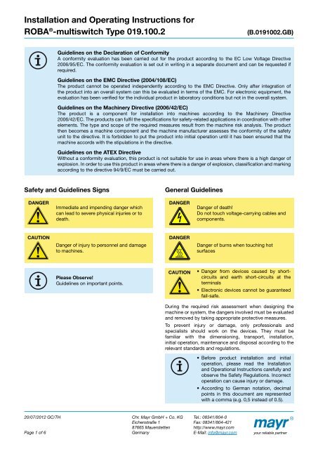
Guidelines on the Declaration of Con<strong>for</strong>mity<br />
A con<strong>for</strong>mity evaluation has been carried out <strong>for</strong> the product according to the EC Low Voltage Directive<br />
2006/95/EC. The con<strong>for</strong>mity evaluation is set out in writing in a separate document <strong>and</strong> can be requested if<br />
required.<br />
Guidelines on the EMC Directive (2004/108/EC)<br />
The product cannot be operated independently according to the EMC Directive. Only after integration of<br />
the product into an overall system can this be evaluated in terms of the EMC. For electronic equipment, the<br />
evaluation has been verified <strong>for</strong> the individual product in laboratory conditions but not in the overall system.<br />
Guidelines on the Machinery Directive (2006/42/EC)<br />
The product is a component <strong>for</strong> installation into machines according to the Machinery Directive<br />
2006/42/EC. The products can fulfil the specifications <strong>for</strong> safety-related applications in coordination with other<br />
elements. The type <strong>and</strong> scope of the required measures result from the machine risk analysis. The product<br />
then becomes a machine component <strong>and</strong> the machine manufacturer assesses the con<strong>for</strong>mity of the safety<br />
unit to the directive. It is <strong>for</strong>bidden to put the product into initial operation until it has been ensured that the<br />
machine accords with the stipulations in the directive.<br />
Guidelines on the ATEX Directive<br />
Without a con<strong>for</strong>mity evaluation, this product is not suitable <strong>for</strong> use in areas where there is a high danger of<br />
explosion. In order to use this product in areas where there is a danger of explosion, classification <strong>and</strong> marking<br />
according to the directive 94/9/EC must be carried out.<br />
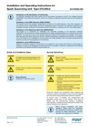
Safety <strong>and</strong> Guidelines Signs<br />
DANGER<br />
CAUTION<br />
Immediate <strong>and</strong> impending danger which<br />
can lead to severe physical injuries or to<br />
death.<br />
Danger of injury to personnel <strong>and</strong> damage<br />
to machines.<br />
Please Observe!<br />
Guidelines on important points.<br />
Chr. <strong>Mayr</strong> GmbH + Co. KG<br />
Eichenstraße 1<br />
87665 Mauerstetten<br />
Germany<br />
General Guidelines<br />
DANGER<br />
DANGER<br />
CAUTION<br />
Danger of death!<br />
Do not touch voltage-carrying cables <strong>and</strong><br />
components.<br />
Danger of burns when touching hot<br />
surfaces<br />
•<br />
•<br />
Danger from devices caused by shortcircuits<br />
<strong>and</strong> earth short-circuits at the<br />
terminals<br />
Electronic devices cannot be guaranteed<br />
fail-safe.<br />
During the required risk assessment when designing the<br />
machine or system, the dangers involved must be evaluated<br />
<strong>and</strong> removed by taking appropriate protective measures.<br />
To prevent injury or damage, only professionals <strong>and</strong><br />
specialists should work on the devices. They must be<br />
familiar with the dimensioning, transport, installation,<br />
initial operation, maintenance <strong>and</strong> disposal according to the<br />
relevant st<strong>and</strong>ards <strong>and</strong> regulations.<br />
• Be<strong>for</strong>e product installation <strong>and</strong> initial<br />
operation, please read the <strong>Installation</strong><br />
<strong>and</strong> Operational <strong>Instructions</strong> carefully <strong>and</strong><br />
observe the Safety Regulations. Incorrect<br />
operation can cause injury or damage.<br />
•<br />
According to German notation, decimal<br />
points in this document are represented<br />
with a comma (e.g. 0,5 instead of 0.5).<br />
Tel.: 08341/804-0<br />
Fax: 08341/804-421<br />
http://www.mayr.com<br />
E-Mail: info@mayr.com<br />
your reliable partner
<strong>Installation</strong> <strong>and</strong> <strong>Operating</strong> <strong>Instructions</strong> <strong>for</strong><br />
ROBA ® -<strong>multiswitch</strong> Type 019.100.2 (B.0191002.GB)<br />
Application<br />
ROBA ® -<strong>multiswitch</strong> fast acting rectifiers are used to connect<br />
DC consumers to alternating voltage supplies, <strong>for</strong> example<br />
electromagnetic brakes <strong>and</strong> clutches (ROBA-stop ® , ROBA ® -<br />
quick, ROBATIC ® ), electromagnets, electrovalves, etc.<br />
Fast acting rectifier ROBA ® -<strong>multiswitch</strong> 019.100.2<br />
• Consistently controlled output voltage in the entire input<br />
voltage range.<br />
• Consumer operation with overexcitation or power<br />
reduction<br />
• Input voltage: 100 – 500 VAC<br />
• Max. output current I RMS : 2 A<br />
• UL-approved<br />
Function<br />
20/07/2012 GC/TH<br />
Page 2 of 6<br />
ROBA ® -<strong>multiswitch</strong> units are not suitable<br />
<strong>for</strong> all applications, e.g. use of the ROBA ® -<br />
<strong>multiswitch</strong> when operating noise-damped<br />
brakes is not possible without taking<br />
additional measures. The product’s suitability<br />
should be checked be<strong>for</strong>e use.<br />
The ROBA ® -<strong>multiswitch</strong> units are (dependent on size) used<br />
<strong>for</strong> an input voltage of between 100 <strong>and</strong> 500. After switchon,<br />
they emit the rectified bridge voltage <strong>for</strong> 50 ms <strong>and</strong> then<br />
control the 90 or 180 VDC overexcitation voltages. After<br />
the overexcitation period, they control the 52 or 104 VDC<br />
holding voltages. The overexcitation period can be adjusted<br />
via a DIP-switch to 150 ms, 450 ms, 1 s, 1,5 s <strong>and</strong> 2 s.<br />
Electrical Connection (Terminals)<br />
1 + 2 Input voltage (fitted protective varistor)<br />
3 + 4 Connection <strong>for</strong> external contact <strong>for</strong> DC-side switchoff<br />
(with an installed bridge, switch-off only takes place ACside<br />
with a longer brake engagement time)<br />
5 + 6 Output voltage (fitted protective varistor)<br />
5<br />
5,6<br />
Chr. <strong>Mayr</strong> GmbH + Co. KG<br />
Eichenstraße 1<br />
87665 Mauerstetten<br />
Germany<br />
Dimensions (mm)<br />
Ø4,5<br />
54<br />
64<br />
54<br />
4,5<br />
69<br />
ON<br />
1 2 3 4<br />
9<br />
15<br />
30<br />
73,6<br />
Tel.: 08341/804-0<br />
Fax: 08341/804-421<br />
http://www.mayr.com<br />
E-Mail: info@mayr.com<br />
your reliable partner<br />
17,5<br />
Accessories:<br />
Mounting bracket set <strong>for</strong><br />
35 mm rail acc. EN 60715:<br />
Article No. 1802911
<strong>Installation</strong> <strong>and</strong> <strong>Operating</strong> <strong>Instructions</strong> <strong>for</strong><br />
ROBA ® -<strong>multiswitch</strong> Type 019.100.2 (B.0191002.GB)<br />
Technical Data<br />
Input voltage<br />
Output voltage<br />
Output current<br />
Max. coil<br />
nominal capacity<br />
L1<br />
L2<br />
L3<br />
M 3 ~<br />
20/07/2012 GC/TH<br />
Page 3 of 6<br />
± 10 %<br />
acc. EN 50160<br />
®<br />
ROBA -<strong>multiswitch</strong><br />
20/019.100.2<br />
U – = 180/104V I max = 2,0A–<br />
200 -<br />
500V~<br />
– +<br />
IN S DC OUT<br />
1 2 3 4 5 6<br />
1 2 3 4<br />
0,15s<br />
0,45s<br />
1,00s<br />
1,50s<br />
2,00s<br />
1 2 3 4 5 6<br />
ON<br />
1 2 3 4<br />
L1<br />
L2<br />
L3<br />
Chr. <strong>Mayr</strong> GmbH + Co. KG<br />
Eichenstraße 1<br />
87665 Mauerstetten<br />
Germany<br />
M 3 ~<br />
Type 019.100.2<br />
Size 10 Size 20<br />
U I [VAC] 100 – 275 200 – 500<br />
Frequency [Hz] 50 – 60 50 – 60<br />
± 10 % U over [VDC] 90 180<br />
± 10 % U hold [VDC] 52 104<br />
at ≤ 45 °C I RMS [A] 2,0 2,0<br />
at max. 70 °C I RMS [A] 1,0 1,0<br />
on<br />
power reduction P nom [W]<br />
on<br />
overexcitation<br />
P nom<br />
[W]<br />
312<br />
at coil nominal voltage 90 V<br />
104<br />
at coil nominal voltage 52 V<br />
Tel.: 08341/804-0<br />
Fax: 08341/804-421<br />
http://www.mayr.com<br />
E-Mail: info@mayr.com<br />
623<br />
at coil nominal voltage 180 V<br />
208<br />
at coil nominal voltage 104 V<br />
Fitted protective varistors U RMS [V] 300 550<br />
Device fuses FF 6,3 A (H) 5 x 20 mm FF 6,3 A (H) 6,3 x 32 mm<br />
Protection IP65 components IP20 terminals<br />
Terminals<br />
Nominal cross-section 1,5 mm 2 (AWG 22-14),<br />
screws M3, max. tightening torque 0,5 Nm<br />
Ambient temperature [°C] -25 up to +70<br />
Storage temperature [°C] -40 up to +105<br />
Con<strong>for</strong>mity markings<br />
<strong>Installation</strong><br />
Wiring Example<br />
(400 VAC, DC-side switching)<br />
The installation position can be user-defined.<br />
Please ensure sufficient heat dissipation <strong>and</strong> air convection!<br />
Do not install near to sources of intense heat!<br />
Special designs with other input <strong>and</strong> output voltages as well as different overexcitation times are available<br />
on request!<br />
Wiring Example<br />
(400 VAC, AC-side switching)<br />
®<br />
ROBA -<strong>multiswitch</strong><br />
20/019.100.2<br />
U – = 180/104V I max = 2,0A–<br />
200 -<br />
500V~<br />
– +<br />
IN S DC OUT<br />
1 2 3 4 5 6<br />
1 2 3 4<br />
0,15s<br />
0,45s<br />
1,00s<br />
1,50s<br />
2,00s<br />
1 2 3 4 5 6<br />
ON<br />
1 2 3 4<br />
your reliable partner
<strong>Installation</strong> <strong>and</strong> <strong>Operating</strong> <strong>Instructions</strong> <strong>for</strong><br />
ROBA ® -<strong>multiswitch</strong> Type 019.100.2 (B.0191002.GB)<br />
Switch-ON<br />
Switch-on always takes place AC-side. Only then is the<br />
overexcitation actuated.<br />
Switch-OFF<br />
If a longer brake engagement time or a quieter switching<br />
noise is required, please switch AC-side. For this, a bridge<br />
must be installed between terminals 3 <strong>and</strong> 4.<br />
Device Fuses<br />
20/07/2012 GC/TH<br />
Page 4 of 6<br />
If short switching times are required, please<br />
switch DC-side. The AC-side should always<br />
be switched as well, in order to activate the<br />
overexcitation.<br />
To protect against damage from short circuits or earth<br />
short-circuits, please add suitable device fuses to the mains<br />
cable.<br />
Short-circuits of earth short-circuits can lead to ROBA ® -<br />
<strong>multiswitch</strong> failures. After fuse elements have reacted to a<br />
malfunction, the ROBA ® - <strong>multiswitch</strong> must be checked <strong>for</strong><br />
functional <strong>and</strong> operational safety (overexcitation voltage,<br />
switch-off voltage, response delay time, holding voltage).<br />
The same procedure is to be carried out after coil failure.<br />
Chr. <strong>Mayr</strong> GmbH + Co. KG<br />
Eichenstraße 1<br />
87665 Mauerstetten<br />
Germany<br />
Overexcitation Time t over<br />
Increased wear (enlarged air gap) as well<br />
as coil heat lengthen the brake separation<br />
time t 2 . There<strong>for</strong>e, when dimensioning the<br />
overexcitation time t over , please select at<br />
least double the separation time t 2 on each<br />
brake Type <strong>and</strong> size (catalogue values).<br />
The overexcitation time can be adjusted via a DIP-Switch to<br />
150 ms, 450 ms, 1 s, 1,5 s <strong>and</strong> 2 s ±20 %. The switches<br />
may only be switched in de-energised state <strong>and</strong> may only be<br />
adjusted as depicted.<br />
DIP-Switch Overexcitation time t over<br />
[s]<br />
ON<br />
1 2 3 4<br />
ON<br />
1 2 3 4<br />
ON<br />
1 2 3 4<br />
ON<br />
1 2 3 4<br />
ON<br />
1 2 3 4<br />
manufacturer-side setting<br />
Recovery Time 100 ms<br />
The recovery time is the amount of time the ROBA ® -<strong>multiswitch</strong><br />
requires in order to reach its starting position after<br />
switch-off. There<strong>for</strong>e, the input voltage may be switched on<br />
again at the earliest after 100 ms.<br />
During cycle operation, please take suitable measures to<br />
ensure that the recovery time of 100 ms is kept to.<br />
Operation on Trans<strong>for</strong>mers<br />
During operation on a trans<strong>for</strong>mer, please ensure sufficient<br />
rigidity on trans<strong>for</strong>mers (min. 3x P nom of the brake). A filter<br />
or external varistor must be installed. Please ensure that the<br />
st<strong>and</strong>ard EN 50160 is kept to <strong>and</strong> that this is re-checked<br />
after installation of the ROBA ® -<strong>multiswitch</strong>.<br />
Tel.: 08341/804-0<br />
Fax: 08341/804-421<br />
http://www.mayr.com<br />
E-Mail: info@mayr.com<br />
0,15<br />
0,45<br />
1,00<br />
1,50<br />
2,15<br />
your reliable partner
<strong>Installation</strong> <strong>and</strong> <strong>Operating</strong> <strong>Instructions</strong> <strong>for</strong><br />
ROBA ® -<strong>multiswitch</strong> Type 019.100.2 (B.0191002.GB)<br />
Coil Capacity<br />
The values <strong>for</strong> the maximum coil nominal capacity stated in the Table are guideline values <strong>for</strong> a switching frequency of<br />
maximum 1 cycle per minute <strong>and</strong> <strong>for</strong> keeping to the permitted current I RMS .<br />
Size Input voltage<br />
U I<br />
10 100 – 275<br />
20 200 – 500<br />
Time Diagram:<br />
U<br />
0<br />
20/07/2012 GC/TH<br />
Page 5 of 6<br />
U over<br />
U nom<br />
U hold<br />
If the switching frequency is larger than 1 cycle<br />
per minute or if the overexcitation time t over<br />
is longer than double the separation time t 2 ,<br />
please observe the following:<br />
P RMS ≤ P nom<br />
The coil capacity P RMS must not be larger than<br />
P nom or the nominal current I RMS which flows<br />
through the ROBA ® -<strong>multiswitch</strong> must not<br />
be exceeded, as otherwise the coil <strong>and</strong> the<br />
ROBA ® -<strong>multiswitch</strong> can fail due to thermic<br />
overload.<br />
At high input voltage <strong>and</strong> low brake<br />
per<strong>for</strong>mance, the initial bridge rectification of<br />
50 ms can lead to thermic overload.<br />
t over<br />
t tot<br />
t on t off<br />
t hold<br />
Coil nominal voltage<br />
U nom<br />
t<br />
Coil nominal capacity<br />
P nom<br />
[VAC] [VDC] [W]<br />
Type 019.100.2 Over-<br />
≤ 45 °C 70 °C excitation<br />
52 104 52 x<br />
Calculations:<br />
Chr. <strong>Mayr</strong> GmbH + Co. KG<br />
Eichenstraße 1<br />
87665 Mauerstetten<br />
Germany<br />
P RMS [W] RMS coil capacity, dependent on the switching<br />
frequency, overexcitation, power reduction <strong>and</strong><br />
switch-on time duration<br />
P nom<br />
P over<br />
P hold<br />
t over<br />
t hold<br />
t off<br />
t tot<br />
U over<br />
P RMS =<br />
P over x t over + P hold x t hold<br />
t tot<br />
[W] Coil nominal capacity (catalogue values or Type<br />
tag)<br />
[W] Coil capacity on overexcitation<br />
P = ( over Uover Unom )² x P nom<br />
[W] Coil capacity on power reduction<br />
P = ( hold Uhold Unom [s] Overexcitation time<br />
)² x P nom<br />
[s] Time of operation with power reduction<br />
[s] Time without voltage<br />
[s] Total time (t over + t hold + t off )<br />
[V] Overexcitation voltage (bridge voltage)<br />
U hold [V] Holding voltage (half-wave voltage)<br />
U nom<br />
[V] Coil nominal voltage<br />
I RMS [A] RMS current, dependent on switching<br />
frequency, overexcitation time <strong>and</strong> switch-on<br />
time duration<br />
I RMS =<br />
P RMS x P nom<br />
U nom ²<br />
Tel.: 08341/804-0<br />
Fax: 08341/804-421<br />
http://www.mayr.com<br />
E-Mail: info@mayr.com<br />
Operation<br />
with<br />
Power<br />
reduction<br />
90 312 156 x<br />
104 208 104 x<br />
180 623 311 x<br />
your reliable partner
<strong>Installation</strong> <strong>and</strong> <strong>Operating</strong> <strong>Instructions</strong> <strong>for</strong><br />
ROBA ® -<strong>multiswitch</strong> Type 019.100.2 (B.0191002.GB)<br />
EMC-compatible <strong>Installation</strong><br />
The measure described <strong>for</strong> compliance with the EMC<br />
directive is examined under laboratory conditions. It cannot<br />
be transferred obligatorily to the condition of a machine<br />
or equipment due to deviations. The inspection tests the<br />
individual components mayr ® -ROBA ® -<strong>multiswitch</strong> <strong>and</strong> the<br />
mayr ® -brake <strong>and</strong> is applicable <strong>for</strong> an input voltage of up to<br />
500 VAC.<br />
L1<br />
L2<br />
PE<br />
Measure<br />
20/07/2012 GC/TH<br />
Page 6 of 6<br />
line<br />
filter<br />
®<br />
ROBA -<strong>multiswitch</strong><br />
20/019.100.2<br />
U – = 180/104V I max = 2,0A–<br />
200 -<br />
500V~<br />
– +<br />
IN S DC OUT<br />
1 2 3 4 5 6<br />
1 2 3 4<br />
0,15s<br />
0,45s<br />
1,00s<br />
1,50s<br />
2,00s<br />
1 2 3 4 5 6<br />
<strong>Installation</strong> of a line filter in the AC-supply line<br />
(e.g. Epcos B84113-C-B30)<br />
•<br />
•<br />
•<br />
•<br />
•<br />
•<br />
ON<br />
1 2 3 4<br />
Avoid antennae effect: Keep the supply<br />
cables as short as possible: do not <strong>for</strong>m<br />
ring or bow shapes with the cables!<br />
Mount good earth connections onto the<br />
metal body of the brake!<br />
Lay control cables separately from power<br />
cables or from strongly pulsating cables!<br />
During operation with a frequency<br />
converter, please ensure<br />
EMC-compatible installation<br />
of the frequency converter!<br />
Please always check the holding voltage<br />
of the ROBA ® -<strong>multiswitch</strong> during<br />
operation of all components in the<br />
system.<br />
For the operation of the ROBA ® -<br />
<strong>multiswitch</strong> in living <strong>and</strong> small business<br />
areas, special precautions must be taken<br />
in order to keep to the correct limit values<br />
<strong>for</strong> this area with the complete system,<br />
e.g. by installing a capacitor. The device<br />
has been inspected individually only <strong>for</strong><br />
industrial areas.<br />
St<strong>and</strong>ards<br />
Chr. <strong>Mayr</strong> GmbH + Co. KG<br />
Eichenstraße 1<br />
87665 Mauerstetten<br />
Germany<br />
EMC inspections<br />
EN 61000-6-2:2006-03 Interference immunity<br />
EN 61000-6-4:2007-09 Interference emission<br />
VDE 0160 / EN 50178:1998-04 Electronic equipment <strong>for</strong><br />
use in power installations<br />
Insulation coordination<br />
acc. VDE 0110 / EN 60664:2008-01<br />
Overvoltage category III<br />
Pollution degree 2<br />
Rated insulation voltage 500 V RMS<br />
Intended use<br />
acc. EN 50178:1998-04<br />
Tel.: 08341/804-0<br />
Fax: 08341/804-421<br />
http://www.mayr.com<br />
E-Mail: info@mayr.com<br />
your reliable partner