Moving to next generation sub-micron CMOS image sensor devices
Moving to next generation sub-micron CMOS image sensor devices
Moving to next generation sub-micron CMOS image sensor devices
- No tags were found...

Create successful ePaper yourself
Turn your PDF publications into a flip-book with our unique Google optimized e-Paper software.
<strong>Moving</strong> <strong>to</strong> <strong>next</strong> <strong>generation</strong> <strong>sub</strong>-<strong>micron</strong><strong>CMOS</strong> <strong>image</strong> <strong>sensor</strong> <strong>devices</strong>Gianluca TestaMicron Technology ItalyTechnology Development©2011 Micron Technology, Inc. All rights reserved. Products are warranted only <strong>to</strong> meet Micron’s production data sheet specifications. Information, products, and/or specifications are<strong>sub</strong>ject <strong>to</strong> change without notice. All information is provided on an “AS IS” basis without warranties of any kind. Dates are estimates only. Drawings are not <strong>to</strong> scale. Micron and theMicron logo are trademarks of Micron Technology, Inc. All other trademarks are the property of their respective owners.September 30, 2011Micron Confidential | ©2011 Micron Technology, Inc. | 1
Outline• Introduction• Imaging systems: CCD vs CIS• Pixel shrinking race▶ Optics diffraction limits vs Pixel Size▶ Technology Solutions <strong>to</strong> reduce pixel size• Future Image Sensor directionsSeptember 30, 2011Micron Confidential | ©2011 Micron Technology, Inc. | 2
<strong>CMOS</strong> <strong>image</strong> <strong>sensor</strong>s in MicronSeptember 30, 2011Micron Confidential | ©2011 Micron Technology, Inc. | 3
Imaging SystemsAu<strong>to</strong>FocusAu<strong>to</strong>ExposureControl andInterfaceSceneThrough the OpticSystem the scene isfocused on the<strong>image</strong>r <strong>sensor</strong>ImagingOptic2-dimensional pixel array convertsthe incident light in<strong>to</strong> an electricalsignal. A color filter array (CFA)separates the color components.Microlens ArrayColor Filter ArrayImage SensorTo produce a color<strong>image</strong> a spatialinterpolation operationcalled DEMOSAIC isneededADCThe analog signalsare read out of the<strong>sensor</strong> array anddigitized by an ADC.ColorProcessingImageEnhancementandCompressionFurther digital signalprocessing is used <strong>to</strong>improve <strong>image</strong> quality.Finally the <strong>image</strong> will becompressed and s<strong>to</strong>red.September 30, 2011Micron Confidential | ©2011 Micron Technology, Inc. | 4
Imaging SystemsAu<strong>to</strong>FocusAu<strong>to</strong>ExposureControl andInterfaceSceneImagingOpticMicrolens ArrayColor Filter ArrayImage SensorImage Sensor CoreADCColorProcessingImageEnhancementandCompressionImage Sensor System On Chip (SOC)September 30, 2011Micron Confidential | ©2011 Micron Technology, Inc. | 5
Sensor - From light <strong>to</strong> colorsEvery pho<strong>to</strong>diode is covered by a single micro lens. Under the micro lens there is acolor filter. A possible Color Filter Array (CFA) layout is the Bayer pattern (Red;Green; Blue) (Bayer, 1975 - Kodak)Why Green are twice Red/Blue?September 30, 2011Micron Confidential | ©2011 Micron Technology, Inc. | 6
<strong>CMOS</strong> Imagers vs. CCDPixel array is made bypho<strong>to</strong>diodes only.Charge <strong>to</strong> Voltage conversion ismade outside the arrayPixel array is not made only bypho<strong>to</strong>diodes. Each pixel has 3 <strong>to</strong> 4transis<strong>to</strong>rs close <strong>to</strong> it.Charge <strong>to</strong> Voltage conversion ismade inside the arraySeptember 30, 2011Micron Confidential | ©2011 Micron Technology, Inc. | 7
<strong>CMOS</strong> Imagers vs. CCDCCDs has been, his<strong>to</strong>rically, the benchmark in professional applications:pho<strong>to</strong>graphic, scientific, and industrial where the highest <strong>image</strong> quality is acritical constraint.<strong>CMOS</strong> <strong>image</strong>rs offer much more integration (a full system on a single chip),lower power dissipation, and the possibility of smaller system size.Main differences between the two technologies<strong>CMOS</strong> ImagerLower costs<strong>CMOS</strong> based fabrication technologyLower power supply voltageLower power consumptionReadout flexibility (windowing and skipping)System-On-Chip (SOC)Low system ComplexityLower Cost of OwnershipHigher SpeedCCDMature and Optimized TechnologyLarger Sensitivity at low light conditionsLower NoiseLower Dark CurrentLower Sensor ComplexityLower R&D CostsHigher Fill Fac<strong>to</strong>rHigher Dynamic RangeSeptember 30, 2011Micron Confidential | ©2011 Micron Technology, Inc. | 8
Image Sensors Units Shipment (M)3,500.00Image Sensors Units (M)3,000.002,500.002,000.001,500.001,000.00500.000.002009 2010 2011 2012 2013 2014 2015<strong>CMOS</strong> 1,250.12 1,548.47 1,950.28 2,304.38 2,563.10 2,806.03 3,027.38CCD 165.06 184.91 188.13 170.50 153.47 132.10 110.39September 30, 2011Micron Confidential | ©2011 Micron Technology, Inc. | 9
Micron CIS Product FamiliesTechnology Nodes150nm, 130nm, 110nm and 90nmSensor DensityOptical FormatApplicationVGA, 1.3Mpixels, 2.0MPixels, 3.2Mpixels, 5Mpixels,8MPixels, 9Mpixels, 10Mpixels, 12Mpixels, 14Mpixelsand 16MpixelsAPS, 1“, 1/2“, 1/2.3“, 1/2.35“, 1/2.5“, 1/3“, 1/3.2“, 1/4“,1/4.5“, 1/5“, 1/6“, 1/11“ and 1/13"Mobile, Au<strong>to</strong>motive/Industrial, Digital Camera, PC/GamingSeptember 30, 2011Micron Confidential | ©2011 Micron Technology, Inc. | 10
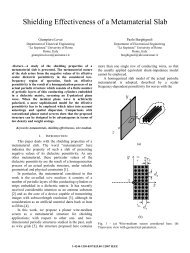
Pixel continues <strong>to</strong> shrink…..Consumer demand for higher megapixel <strong>sensor</strong>s in smaller form fac<strong>to</strong>r<strong>devices</strong> has driven a shrinking pixel race amongst <strong>image</strong> <strong>sensor</strong> producers.At the same time, higher quality of the output <strong>image</strong> (DSC-like quality formobile applications) is required.Post processing circuitryPixel arrayConsumers: 8-12 Mpixel range.Professional cameras: 20-40 Mpixel rangeAerospace applications: 100 Mpixels.Pixel size in current <strong>CMOS</strong> <strong>sensor</strong>s forconsumers ranges from 2.2um <strong>to</strong> 1.1um.0.9um pixels are under developmentSeptember 30, 2011Micron Confidential | ©2011 Micron Technology, Inc. | 11
Smaller and smaller pixels…..Pro:• Lower chip cost• Smaller optics size and lower cost• Smaller camera modules more desirable for integration in<strong>to</strong> consumer products• Higher resolution <strong>image</strong>s for same opticsCons:• Degraded Pixel Performance▶▶▶▶▶▶Lower quantum efficiency due <strong>to</strong> fill fac<strong>to</strong>rReduced SNR under low lightSmaller full-wellIncreased op<strong>to</strong>electronic crosstalkStack height and aperture degrades chief ray angleHigher Dark Current• Entering visible light diffraction limit (less return on resolution)• More stringent requirements on optical system quality• More megapixels makes getting data off chip at same frame rate more challengingSeptember 30, 2011Micron Confidential | ©2011 Micron Technology, Inc. | 12
Smaller and smaller pixels…..In the following slides, we will focus on twofundamental properties:Diffraction-limited blurringPho<strong>to</strong>n noiseSeptember 30, 2011Micron Confidential | ©2011 Micron Technology, Inc. | 13
Lens diffraction limitF=1 f≈'2sinθD1F = ='2sinϑDfDθfA perfect lens can only focus a point<strong>to</strong> a diffraction-limited spot known asan Airy disk, surrounded by higherorder diffraction disks.For λ = 550 nm and F = 2.8, dAiry = 3.7µmThe Physical dimensions of pixels arecomparable or smaller than thediffraction limit of light at thewavelengths of interestd Airy = 2.44λFCurrent pixel in mobile applicationsare in the range 2.2-0.9 um!September 30, 2011Micron Confidential | ©2011 Micron Technology, Inc. | 14
Lens resolutionFor a particular wavelength and aperture, resolution and contrast aredetermined by the spacing between two adjacent Airy disks.Higher resolution, lower contrastLower resolution, higher contrastSeptember 30, 2011Micron Confidential | ©2011 Micron Technology, Inc. | 15
Do <strong>sensor</strong>s “out resolve” lens capabilities?In the pho<strong>to</strong>graphy, the signal that comes in<strong>to</strong> the lens is not band-limited, butthe diffraction puts a limit <strong>to</strong> the maximum spatial frequency transferred fromthe lens <strong>to</strong> the <strong>sensor</strong> (lens resolution).Digital capture <strong>sensor</strong>s are bandwidth-limited. The sampling (spatial) frequencyis related <strong>to</strong> the pixel pitch ∆.Sampling theoremIf the signal is limited <strong>to</strong> frequencies smaller than f c = 1/2 ∆ (Nyquist frequency),the information is completely captured, otherwise the power spectral densitylying outside the frequency range (-f c , f c ) is spuriously moved in<strong>to</strong> that range(aliasing).September 30, 2011Micron Confidential | ©2011 Micron Technology, Inc. | 16
Do <strong>sensor</strong>s “out resolve” lens capabilities?Most cameras useanti-aliasing opticallow-pass filters(OLPF)MTF (%) MTF (%)Spatial FrequencyMTF for an imaging lensSpatial FrequencyMTF for a typical OLPFSeptember 30, 2011Micron Confidential | ©2011 Micron Technology, Inc. | 17
Pho<strong>to</strong>n Shot NoisePho<strong>to</strong>n detection is essentially a random process obeying Poisson statistics.Noise(pho<strong>to</strong>n)=SNR(pho<strong>to</strong>n)=NNN=NSmaller Pixel Size = Lower SNRSeptember 30, 2011Micron Confidential | ©2011 Micron Technology, Inc. | 18
Pho<strong>to</strong>n loss mechanisms in real CISIn a real <strong>sensor</strong>, the surface is far more complicated than just an array ofpixel. The light must pass through the metal routing that brings electricalsignals in and out of the pixel array. Additional diffractive, refractive andreflective losses must be minimizedGreen filterPassivation layersRed filterRefraction at allinterfacesM3M2Diffraction atmetal apertureCTSTIM1PolyCapPD implantReflection atmetal surfaceSeptember 30, 2011Micron Confidential | ©2011 Micron Technology, Inc. | 19
• Design solutions:▶ Optimize pixel readout architecture <strong>to</strong> reduce transis<strong>to</strong>r count andeliminate metal lines• Design/Technology solutions:▶Reduce design rules (use smaller line widths, reduce active spacing, etc.)<strong>to</strong> increase fill fac<strong>to</strong>r• Technology solutions:How <strong>to</strong> reduce pixel size….▶▶▶▶Add optical layers (micro lens, light pipe) <strong>to</strong> funnel light <strong>to</strong> the sensitiveportion of pixel.Match the refraction index of optical layersIncrease Pho<strong>to</strong>diode depth <strong>to</strong> absorb completely all light coming on<strong>to</strong> thePDMove from front side <strong>to</strong> backside illuminationSeptember 30, 2011Micron Confidential | ©2011 Micron Technology, Inc. | 20
• Design solutions:▶ Optimize pixel readout architecture <strong>to</strong> reduce transis<strong>to</strong>r count andeliminate metal lines• Design/Technology solutions:▶Reduce design rules (use smaller line widths, reduce active spacing, etc.)<strong>to</strong> increase fill fac<strong>to</strong>r• Technology solutions:How <strong>to</strong> reduce pixel size▶▶▶▶Add optical layers (micro lens, light pipe) <strong>to</strong> funnel light <strong>to</strong> the sensitiveportion of pixel.Match the refraction index of optical layersIncrease Pho<strong>to</strong>diode depth <strong>to</strong> absorb completely all light coming on<strong>to</strong> thePDMove from front side <strong>to</strong> backside illuminationSeptember 30, 2011Micron Confidential | ©2011 Micron Technology, Inc. | 21
• Design solutions:▶ Optimize pixel readout architecture <strong>to</strong> reduce transis<strong>to</strong>r count andeliminate metal lines• Design/Technology solutions:▶Reduce design rules (use smaller line widths, reduce active spacing, etc.)<strong>to</strong> increase fill fac<strong>to</strong>r• Technology solutions:How <strong>to</strong> reduce pixel size▶▶▶▶Add optical layers (micro lens, light pipe) <strong>to</strong> funnel light <strong>to</strong> the sensitiveportion of pixel.Match the refraction index of optical layersIncrease Pho<strong>to</strong>diode depth <strong>to</strong> absorb completely all light coming on<strong>to</strong> thePDMove from front side <strong>to</strong> backside illuminationSeptember 30, 2011Micron Confidential | ©2011 Micron Technology, Inc. | 22
Use smaller Design Rules…• Pixel size shrinkage requires advanced processes with tighter design rules.▶▶▶For the same pixel architecture and process, pixel size shrink comes onlyfrom pho<strong>to</strong>diode (PD) shrink, which makes a quick drop in PD fill fac<strong>to</strong>rand optical opening fac<strong>to</strong>r, making impossible <strong>to</strong> achieve scaled pixelperformance;PD fill fac<strong>to</strong>r is mainly limited by FEOL and contact process design rules;Pixel optical opening fac<strong>to</strong>r is limited by BEOL process design rules, suchas metal line width and space, via size and surround.Fill fac<strong>to</strong>r (FF) = Apd / Apix [%]Apd Pho<strong>to</strong>diode areaApix Pixel areaSeptember 30, 2011Micron Confidential | ©2011 Micron Technology, Inc. | 23
Cu BEOL 90nm technology nodePass Ni<strong>to</strong>penAluminumPADM4BloKColor filters + uLensILD3M3ILD2M2ILD1M1BloKBloKBloKBloKTEOSLight pipePass nitBPSGSubstratePerypho<strong>to</strong>diodeArraySi-<strong>sub</strong>strateSeptember 30, 2011Micron Confidential | ©2011 Micron Technology, Inc. | 24
• Design solutions:▶ Optimize pixel readout architecture <strong>to</strong> reduce transis<strong>to</strong>r count andeliminate metal lines• Design/Technology solutions:▶Reduce design rules (use smaller linewidths, reduce active spacing, etc.)<strong>to</strong> increase fill fac<strong>to</strong>r• Technology solutions:How <strong>to</strong> reduce pixel size▶▶▶▶Add optical layers (microlens, light pipe) <strong>to</strong> funnel light <strong>to</strong> the sensitiveportion of pixel.Match the refraction index of optical layersIncrease Pho<strong>to</strong>diode depth <strong>to</strong> absorb completely all light coming on<strong>to</strong> thePDMove from front side <strong>to</strong> backside illuminationSeptember 30, 2011Micron Confidential | ©2011 Micron Technology, Inc. | 25
Optimize the Optical stackMicro lenses, above the CFA or combined with inner lenses, funnel lightaway from non sensitive portions of pixel. They increase the effective fillfac<strong>to</strong>r and maximize light delivered <strong>to</strong> the PD.Pho<strong>to</strong>diodePho<strong>to</strong>diodeSeptember 30, 2011Micron Confidential | ©2011 Micron Technology, Inc. | 26
MICRO LENS FORMATIONCOAT – EXPOSE - DEVELOPBLEACH AND REFLOWSeptember 30, 2011Micron Confidential | ©2011 Micron Technology, Inc. | 27
Without UlensMicro-lensWith UlensClick <strong>to</strong> start movie (works only in presentation mode)Click <strong>to</strong> start movie (works only in presentation mode)September 30, 2011Micron Confidential | ©2011 Micron Technology, Inc. | 28
Optical stack - “Step Index” Light Guides• A solution <strong>to</strong> overcome refraction andreflection losses, and <strong>to</strong> help withMicrolens and planarization layerdiffraction limitations is the use of lightguides. The “Step Index” approachrequires a “core” material with thefollowing characteristics:Colored filter arrayNitride passivationM2▶▶▶Good transparency in the visible spectralrange;Refractive-index higher than thesurrounding oxide for <strong>to</strong>tal reflection at theinterface;Easy <strong>to</strong> integrate (heat resistance, crackthreshold and Adhesion for following.processes).M1September 30, 2011Micron Confidential | ©2011 Micron Technology, Inc. | 29
“Step Index” Light GuidesSimulation Movies: 0 deg CRAReflection from metal structures contribute <strong>to</strong> QE losses in pixelwithout light guide while in the pixel with light guide these losses areminimal.Cross Talk is also smaller in the case of pixel with light guide:there is a wider gap between light fields localized in active regions ofneighboring pixels.September 30, 2011Micron Confidential | ©2011 Micron Technology, Inc. | 30
“Step Index” Light GuidesSimulation Movies: 15 deg CRAReflection from metal structures contribute <strong>to</strong> QE losses in pixelwithout light guide while in the pixel with light guide these losses areminimal.Cross Talk is also smaller in the case of pixel with light guide:there is a wider gap between light fields localized in active regions ofneighboring pixels.September 30, 2011Micron Confidential | ©2011 Micron Technology, Inc. | 31
• Design solutions:▶ Optimize pixel readout architecture <strong>to</strong> reduce transis<strong>to</strong>r count andeliminate metal lines• Design/Technology solutions:▶Reduce design rules (use smaller line widths, reduce active spacing, etc.)<strong>to</strong> increase fill fac<strong>to</strong>r• Technology solutions:How <strong>to</strong> reduce pixel size▶▶▶▶Add optical layers (micro lens, light pipe) <strong>to</strong> funnel light <strong>to</strong> the sensitiveportion of pixel.Match the refraction index of optical layersIncrease Pho<strong>to</strong>diode depth <strong>to</strong> absorb completely all light coming on<strong>to</strong> thePDMove from front side <strong>to</strong> backside illuminationSeptember 30, 2011Micron Confidential | ©2011 Micron Technology, Inc. | 32
Match the refraction index of optical layersIncident light is reflected at the interface of two materials when the refractiveindices are different. Reflectivity (R) of light rays that are incidentperpendicular <strong>to</strong> the materials is given byR=⎛⎜⎝nn11−+nn22⎞⎟⎠2Green filterRed filterwith the refractiveCTSTIM3M2Passivation layersM1CapPolyPD implantindices of 1.45 for SiO 2and 3~5 for Si, morethan 20 <strong>to</strong> 30 percen<strong>to</strong>f the incident light isreflected at the siliconsurface in the visiblelight range (400nm–700nm)!September 30, 2011Micron Confidential | ©2011 Micron Technology, Inc. | 33
• Design solutions:▶ Optimize pixel readout architecture <strong>to</strong> reduce transis<strong>to</strong>r count andeliminate metal lines• Design/Technology solutions:▶Reduce design rules (use smaller line widths, reduce active spacing, etc.)<strong>to</strong> increase fill fac<strong>to</strong>r• Technology solutions:How <strong>to</strong> reduce pixel size▶▶▶▶Add optical layers (micro lens, light pipe) <strong>to</strong> funnel light <strong>to</strong> the sensitiveportion of pixel.Match the refraction index of optical layersIncrease Pho<strong>to</strong>diode depth <strong>to</strong> absorb completely all light coming on<strong>to</strong> thePDMove from front side <strong>to</strong> backside illuminationSeptember 30, 2011Micron Confidential | ©2011 Micron Technology, Inc. | 34
Increase Pho<strong>to</strong> Diode depth• The Integration of the Deep Pho<strong>to</strong>diode is atrue challenge from a technology developmentpoint of view, for the very deep implant steprequired (MeV);• We need <strong>to</strong> develop pho<strong>to</strong> resist maskshaving small features and blocking power highenough for the needed implant energies (AR~ 10).Pho<strong>to</strong>diodeIsolationScanning Capacitance MicroscopyAnalysis in the Pixel array.September 30, 2011Micron Confidential | ©2011 Micron Technology, Inc. | 35
• Design solutions:▶ Optimize pixel readout architecture <strong>to</strong> reduce transis<strong>to</strong>r count andeliminate metal lines• Design/Technology solutions:▶Reduce design rules (use smaller line widths, reduce active spacing, etc.)<strong>to</strong> increase fill fac<strong>to</strong>r• Technology solutions:How <strong>to</strong> reduce pixel size▶▶▶▶Add optical layers (micro lens, light pipe) <strong>to</strong> funnel light <strong>to</strong> the sensitiveportion of pixel.Match the refraction index of optical layersIncrease Pho<strong>to</strong>diode depth <strong>to</strong> absorb completely all light coming on<strong>to</strong> thePDMove from front side <strong>to</strong> backside illuminationSeptember 30, 2011Micron Confidential | ©2011 Micron Technology, Inc. | 36
Back Side Illumination – TSV approachBackside illumination (BSI) flips the <strong>image</strong> <strong>sensor</strong> upside down so it absorbs light fromthe backsideAs an alternative <strong>to</strong> the more common front-side illumination (FSI) technique, it offersthe most direct path for light <strong>to</strong> strike the pixelIn principle, BSI provides a better fill fac<strong>to</strong>r, higher QE, lower cross talk, and metalrouting flexibilityuLensCFAARCPho<strong>to</strong> diodeSiliconTransis<strong>to</strong>rsMetal routingSeptember 30, 2011Micron Confidential | ©2011 Micron Technology, Inc. | 37
Poolside Day ProcessedSeptember 30, 2011Micron Confidential | ©2011 Micron Technology, Inc. | 38
Poolside Night ProcessedSeptember 30, 2011Micron Confidential | ©2011 Micron Technology, Inc. | 39
Future Directions• 1970 Charge‐coupled device• 1993 <strong>CMOS</strong> active pixel <strong>image</strong> <strong>sensor</strong>What comes <strong>next</strong>?‐ “Black silicon”‐ “Quanta Image Sensors”‐ “Organic stacked structures”• - ……September 30, 2011Micron Confidential | ©2011 Micron Technology, Inc. | 40
September 30, 2011