EUROSTER 11/11C - Logitron
EUROSTER 11/11C - Logitron
EUROSTER 11/11C - Logitron

Create successful ePaper yourself
Turn your PDF publications into a flip-book with our unique Google optimized e-Paper software.
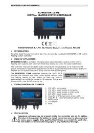
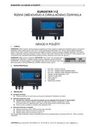
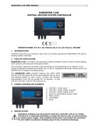
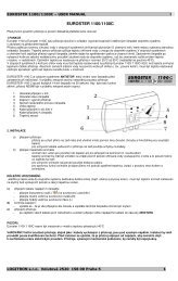
<strong>EUROSTER</strong> <strong>11</strong>, <strong>11</strong>C USER MANUAL 1<strong>EUROSTER</strong> <strong>11</strong>/<strong>11</strong>CCENTRAL HEATING PUMP CONTROLLERMANUFACTURER: P.H.P.U. AS, Polanka 8a/3, 61-131 Poznań, POLAND1. INTRODUCTIONCarefully study this user manual to learn how to correctly operate the <strong>EUROSTER</strong> <strong>11</strong>/<strong>11</strong>Ccentral heating (CH) pump controller.2. FIELD OF APPLICATION<strong>EUROSTER</strong> <strong>11</strong>/<strong>11</strong>C is an electronic controller used to automatically turn ON/OFF CH systemcirculation pump depending on CH system water temperature. The pump may circulate waterthrough a system heated by a coal- or gas-fired boiler. Water temperature is sensed by asensor located at the CH system inlet.The controller will also turn the pump OFF as soon as coal-fired boiler flame is put out. Watershould not be circulated unless it is heated by the boiler since chimney air draft cools down theboiler water much faster than the radiator water.Controller is equipped with a knob used to preset optimum CH system water temperature(most often around 40ºC). If the controller cooperates with a gas-fired boiler, its setpoint MUST BE LOWER than the boiler thermostat set point. Set the controller setpoint higher than the dew point in order to prevent boiler sweat during the processof heating the water up.The <strong>EUROSTER</strong> <strong>11</strong>/<strong>11</strong>C controller features the ANTY STOPfunction that prevents idle pump rotors and valves againstseizing. Once the heating season is over, every 14 days thefunction automatically turns ON the pumps and the valves for30 seconds. To that end the controller must be left powered up.3. VISIBLE CONTROLLER ELEMENTS1. Mains switch2. 230 VAC~ mains input3. 230 VAC~ power supply to pump4. Input for the boiler temperature sensor cable5. Temperature preset knob6. Controller turned on green LED7. Pump turned on red LED8. Continuous operation switch
<strong>EUROSTER</strong> <strong>11</strong>, <strong>11</strong>C USER MANUAL 24. INSTALLATIONThe procedure:Hazardous voltages may be present inside the controller and on its cables.Therefore it is expressly forbidden to install the device prior to disconnectingits mains power supply. Only qualified technicians may install the controller.Do not install any devices showing signs of any mechanical damage.a) Mount the controller: using a pair of supplied nylon nail-it fasteners (anchors) mount the controller box on awall (or any other suitable supporting structure) using fasteners fix controller cables to the wall.b) Install temperature sensor: do not immerse sensor in liquids nor install it within stream of flue gases install the CH system inlet temperature sensor at the boiler point specially designed forthat purpose or on an unshielded boiler outlet pipe (as close to the boiler as possible) using hose clips tighten the sensor to the pipe.c) Hook up pump power supply cable: connect yellow (or yellow-green) PE wire with the terminal connect blue wire with the N terminal connect brown wire with the L terminal.d) Verify the connections: check up all cable connections and tighten terminal box lids.e) Hook up the controller: make sure controller cables are protected against incidental cut off plug the controller power supply cable into a 230V/50Hz mains socket equipped with agrounding pin.The controller must not be installed in a place where the ambienttemperature may exceed 40ºC.5. TURNING THE CONTROLLER ONTurn the controller mains switch (1 in section 3) into the “I” position.Green LED (6 in section 3) goes ONIn case of the E<strong>11</strong>C controller model its ANTY STOP function turns the pump on forabout 30 seconds (red LED goes ON)Using the knob set the desired temperature.6. AUTOMATIC OPERATIONThe <strong>EUROSTER</strong> E<strong>11</strong>/<strong>11</strong>C controller engages/disengages CH system circulation pumpdepending on sensor temperature in relation to the knob-preset temperature set point. Thepump is turned ON as soon as sensor temperature exceeds the set point, and is turned OFF assoon as it drops below the set point.MANUAL OPERATIONManual pump switch of the <strong>EUROSTER</strong> E<strong>11</strong>/<strong>11</strong>C controller may be useful e.g. to help deaeratethe system or in case of a failure of the temperature sensor.1. Turn the continuous operation switch (8 in section 3) into the “I” position (red LED goes ON).2. The pump will be engaged regardless of the actual sensor temperature in relation to thecontroller set point.7. TROUBLESHOOTINGa) Device is dead (green LED does not go ON)Burnt mains fuse or ROM failure. Replace the fuse or have the controller serviced.
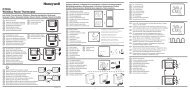
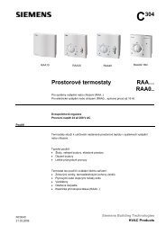
<strong>EUROSTER</strong> <strong>11</strong>, <strong>11</strong>C USER MANUAL 3b) Pump does not operateUse manual operation switch (8) to turn the pump ON. If the red LED (7) goes ON but thepump does not operate, check if pump operates when connected directly to a mains socket. Ifso, have the controller serviced.Turn the knob all the way towards minimum temperature and heat temperature sensor. If thered LED (7) does not go ON, have the controller serviced.c) Pump continuously engagedMake sure that manual operation switch (Błąd: Nie znaleziono źródła odwołania) is not turnedON.Turn the knob all the way towards maximum temperature. If the red LED (7) is still ON, havethe controller serviced. Otherwsie (the LED goes OFF but the pump does not stop) check theconnections.8. COMPATIBILITY WITH STANDARDS/CERTIFICATESThe <strong>EUROSTER</strong> <strong>11</strong>/<strong>11</strong>C controller meets all requirements of the EMC and the LVD EUDirectives. The CE Conformity Declaration is available on the http://www.euroster.com.plInternet webpage.9. SPECIFICATIONSa) Mains 230 V 50Hzb) Output rated load 3 Ac) Hysteresis 5°Cd) Length of cables 1.5 me) Dimensions (width x height x depth) 150 x 90 x 54 mm10. KIT CONTENTSa) controller box with temperature sensorb) sensor hose clipc) box fasteners/anchorsd) this Installation & Operation Manuale) template to drill holes for fasteners/anchors<strong>11</strong>. CONNECTION DIAGRAMSDiagram presented below is simplified (not every element necessary to correctly operate thesystem is shown).1. <strong>EUROSTER</strong> <strong>11</strong>/<strong>11</strong>C controller2. CH boiler (secondary)3. CH boiler (primary)4. Temperature sensor5. CH pump6. Heat load (radiator)
<strong>EUROSTER</strong> <strong>11</strong>, <strong>11</strong>C USER MANUAL 412. ELECTRONIC WASTE MANAGEMENT INFORMATIONWe made every effort to get as a long controller lifetime as possible.However, the device is subject to natural tear and wear. We ask you to havea controller that will not meet your requirements any more brought in to anelectronic waste management facility. Electronic waste is collected free ofcharge by local distributors of electronic equipment.Inappropriate management of electronic waste may lead to an unnecessaryenvironment pollution.Cardboard boxes should be disposed of at a paper recycling facility.<strong>EUROSTER</strong> <strong>11</strong>/<strong>11</strong>C CONTROLLER WARRANTY CERTIFICATEWarranty terms:1. Warranty is valid for 24 months from the controller sale date.2. Warranty is valid exclusively on the territory of Poland.3. Claimed controller together with this warranty certificate must be supplied to theseller or directly mailed via Poczta Polska mail operator to the manufacturer.4. Warranty claims shall be processed within 14 business days from the date themanufacturer has received the claimed device.5. Controller may be repaired exclusively by the manufacturer or by other party clearlyauthorized by the manufacturer.6. Warranty becomes invalidated in case of any mechanical damage, incorrectoperation and/or making any repairs by unauthorized persons.7. This consumer warranty does not exclude, restrict nor suspend any right of theBuyer ensuing if the product would not meet any of the sale contract terms.........................................................................................................................sale date serial number/date of manufacture signature/stampService phone (48) 655-71-20-12Business entity that issued this warranty certificate:P.H.P.U. AS Agnieszka Szymańska-Kaczyńska, Chumiętki 4, 63-840 Krobia, Poland