IA-PC HPET (High Precision Event Timers) Specification 1.0a - Intel
IA-PC HPET (High Precision Event Timers) Specification 1.0a - Intel
IA-PC HPET (High Precision Event Timers) Specification 1.0a - Intel
- No tags were found...

Create successful ePaper yourself
Turn your PDF publications into a flip-book with our unique Google optimized e-Paper software.
<strong>IA</strong>-<strong>PC</strong> <strong>HPET</strong> (<strong>High</strong> <strong>Precision</strong> <strong>Event</strong> <strong>Timers</strong>)<strong>Specification</strong>Revision: <strong>1.0a</strong>Date: October 2004______________________________________________________________________________________<strong>IA</strong>-<strong>PC</strong> <strong>HPET</strong> <strong>Specification</strong> Rev <strong>1.0a</strong> 1
LEGAL DISCLAIMERTHIS SPECIFICATION IS PROVIDED "AS IS" WITH NO WARRANTIESWHATSOEVER, INCLUDING ANY WARRANTY OF MERCHANTABILITY, NON-INFRINGEMENT, FITNESS FOR ANY PARTICULAR PURPOSE, OR ANY WARRANTYOTHERWISE ARISING OUT OF ANY PROPOSAL, SPECIFICATION OR SAMPLE.<strong>Intel</strong> disclaims all liability, including liability for infringement of any proprietary rights,relating to use of information in this specification. No license, express or implied, byestoppels or otherwise, to any intellectual property rights is granted herein.This specification is a preliminary draft provided for comment and informational purposesonly, and is subject to change without any notice, obligation or liability. Readers shouldnot rely on this specification in any way for product design purposes.It is <strong>Intel</strong>'s intent to provide a Version 1.0 of this specification, that will be made availablesubject to an appropriate license agreement. However, <strong>Intel</strong> is under no obligation orliability to do so.The contents of the areas marked as "reserved" in this specification will not belicensed under the <strong>Intel</strong> license for this specification.<strong>IA</strong>-<strong>PC</strong> <strong>HPET</strong> <strong>Specification</strong>Copyright © 1999-2004 <strong>Intel</strong> CorporationAll rights reserved.*THIRD-PARTY BRANDS AND NAMES MAY BE CLAIMED AS THE PROPERTY OF OTHERS.______________________________________________________________________________________<strong>IA</strong>-<strong>PC</strong> <strong>HPET</strong> <strong>Specification</strong> Rev <strong>1.0a</strong> 2
Table of Contents1. <strong>IA</strong>-<strong>PC</strong> <strong>HPET</strong>........................................................................................................................................... 41.1 Revision History:............................................................................................................................ 41.2 Scope .............................................................................................................................................. 51.3 Terminology ................................................................................................................................... 62. Hardware Overview................................................................................................................................ 72.1 Register Model Overview............................................................................................................... 82.1.1 Memory Map .......................................................................................................................... 82.2 Minimum Recommended Hardware Implementation .................................................................... 92.3 Register Definitions...................................................................................................................... 102.3.1 Register Overview ................................................................................................................ 102.3.2 Programming Requirements ................................................................................................. 102.3.3 Power Management Considerations ..................................................................................... 102.3.4 General Capabilities and ID Register ................................................................................... 11General Capability and ID Register Addressing...................................................................................112.3.5 General Configuration Register............................................................................................ 122.3.6 General Interrupt Status Register.......................................................................................... 142.3.7 Main Counter Register.......................................................................................................... 152.3.8 Timer N Configuration and Capabilities Register ................................................................ 162.3.9 Timer N Comparator Register .............................................................................................. 192.3.9.1 Register Definition and Usage Model .............................................................................. 202.3.9.2 Periodic vs. Non-Periodic Modes ..................................................................................... 212.3.9.2.1 Non-Periodic Mode.................................................................................................... 212.3.9.2.2 Periodic Mode............................................................................................................ 212.3.9.2.3 Read/Write Paths for Periodic Mode Vs One-Shot Mode ......................................... 222.3.10 Timer N FSB Interrupt Route Register................................................................................. 232.4 Theory Of Operation .................................................................................................................... 232.4.1 Timer Accuracy Rules .......................................................................................................... 232.4.2 Interrupt Mapping................................................................................................................. 242.4.2.1 Mapping Option #1: LegacyReplacement Option ........................................................... 242.4.2.2 Mapping Option #2: Standard Option ............................................................................. 242.4.2.3 Mapping Option #3: FSB Option..................................................................................... 242.4.3 Periodic vs. Non-Periodic Modes ......................................................................................... 242.4.3.1 Non-Periodic Mode .......................................................................................................... 242.4.3.2 Periodic Mode...................................................................................................................252.4.4 Enabling the <strong>Timers</strong>.............................................................................................................. 252.4.5 Interrupt Levels..................................................................................................................... 252.4.6 Handling Interrupts............................................................................................................... 262.4.7 Issues related to 64-bit <strong>Timers</strong> with 32-bit CPUs................................................................. 263. Enumeration & Configuration of <strong>HPET</strong>............................................................................................... 273.1 Initial State of <strong>Event</strong> Timer Hardware.......................................................................................... 273.2 BIOS Initialization........................................................................................................................ 273.2.1 Assign memory to Timer Block(s) ....................................................................................... 273.2.2 <strong>HPET</strong> Block Interrupt Routing............................................................................................. 273.2.2.1 Routing Interrupts for <strong>HPET</strong> Blocks that do not support 8254/RTC IRQ Routing.......... 273.2.2.2 Routing Interrupts for <strong>HPET</strong> Blocks that support 8254/RTC IRQs ................................. 283.2.3 Considerations for Platforms without Legacy <strong>Timers</strong> .......................................................... 293.2.4 Create ACPI 2.0 <strong>HPET</strong> Description Table (<strong>HPET</strong>).............................................................. 303.2.5 Describe <strong>Event</strong> Timer(s) in ACPI Name space .................................................................... 323.2.5.1 ACPI Name Space Example............................................................................................. 323.2.6 Recommendations for OS Initialization code....................................................................... 32______________________________________________________________________________________<strong>IA</strong>-<strong>PC</strong> <strong>HPET</strong> <strong>Specification</strong> Rev <strong>1.0a</strong> 3
1. <strong>IA</strong>-<strong>PC</strong> <strong>HPET</strong>1.1 Revision History:VersionComments0.97 Last Updated: 03/07/2000• Incorporated technical editing changes, released for external feedback.0.97a Last Updated: 05/18/2000• Incorporated various non-technical and legal feedbacks.0.98 01/20/2002• Product name changed: from Multimedia Timer to <strong>HPET</strong> (<strong>High</strong> <strong>Precision</strong> <strong>Event</strong> Timer)• Technologic term changed: from Legacy Mode to LegacyReplacement Mode for clarity purpose• ETDT ACPI table changed: ETDT (<strong>Event</strong> Timer Descriptor Table) is changed to <strong>HPET</strong> table and its content of the tablehas been updated.• <strong>IA</strong>64 platform support: Use GAS(Generic Address Structure) format in <strong>HPET</strong> table and up to 64KB timer block.0.98a 08/31/2001• Modified the accuracy of clock frequency drift to 0.05%• Add “write lock” note to the programming requirement1.0 6/8/2004• Removed color-code for read-only fields• Added programming notes for 64-bit register access in a 64-bit platform• Explicitly mark “Reserved” in reserved fields of FSB Registers<strong>1.0a</strong> 6/8/2004• Clarifications to 64 bit accesses.• General cleanup______________________________________________________________________________________<strong>IA</strong>-<strong>PC</strong> <strong>HPET</strong> <strong>Specification</strong> Rev <strong>1.0a</strong> 4
1.2 ScopeThis specification provides register model and programming interface definitions for new event timerhardware for use on <strong>Intel</strong> Architecture-based Personal Computers. In this specification, the terms ‘<strong>IA</strong>-<strong>PC</strong><strong>HPET</strong> and ‘<strong>Event</strong> <strong>Timers</strong>’ refer to the same timer hardware.The <strong>IA</strong>-<strong>PC</strong> <strong>HPET</strong> <strong>Specification</strong> defines timer hardware that is intended to initially supplement andeventually replace the legacy 8254 Programmable Interval Timer and the Real Time Clock PeriodicInterrupt generation functions that are currently used as the ‘de-facto’ timer hardware for <strong>IA</strong>-<strong>PC</strong>s.This new timer hardware can be used by system software for:• Synchronizingo Real-Time Digital Audio & Video Streams• 64-bit free running up-counter• Schedulingo Threads, Tasks, Processes, etc.• Fixed Rate (Periodic) Interrupt Generation• System Heart Beat• Non-Real Time Thread Scheduler• Variable Rate (One-Shot) Interrupt Generation• Scheduling real time tasks associated with host-based signal processingapplications• Time Stampingo On Multiprocessor platforms• 64-Bit free running up-counter can be utilized as DIG64 “platform timer” forTime Stamping Applications. This provides a time-base that is insensitive toclock frequency drifts on individual CPU’s on a N-Way MP systems.Note:The name of the timer block has been changed from Multimedia Timer to <strong>HPET</strong> (<strong>High</strong> <strong>Precision</strong><strong>Event</strong> Timer). However, before the new name was adopted, many related documents continue to useor reference the term of “Multimedia Timer”. Therefore, for the purposes of designing products tothis specification, the terms <strong>HPET</strong>, Multimedia Timer, MMT and MM Timer should be treated asthe same timer hardware.______________________________________________________________________________________<strong>IA</strong>-<strong>PC</strong> <strong>HPET</strong> <strong>Specification</strong> Rev <strong>1.0a</strong> 5
1.3 TerminologyTerm<strong>IA</strong><strong>PC</strong><strong>IA</strong>-<strong>PC</strong>PITRTCSCIFSBMM• Timer• <strong>Event</strong> Timer• <strong>HPET</strong>• MM Timer• MMTTimer Block32-Bit Timer64-Bit TimerDefinition for this document<strong>Intel</strong> ArchitecturePersonal Computer<strong>Intel</strong> Architecture-based <strong>PC</strong>8254 Programmable Interval TimerReal Time ClockSystem Configuration InterruptFront Side BusMultimediaThe terms Timer, <strong>Event</strong> Timer, <strong>HPET</strong>, MMT and MM Timer refer to the combination ofa Counter, Comparator, and Match Register. The Comparator compares the contents ofthe Match Register against the value of a free running up-counter. When the output of theup-counter equals the value in the match register an interrupt is generated. The <strong>IA</strong>-<strong>PC</strong><strong>HPET</strong> Architecture allows up to 32 compare/match registers per counter. Each of the 32comparators can output an interrupt.Each Timer Block consists of a single counter that feeds up to 32 comparators. EachTimer Block in the system can have different clocking attributes.Comparator Register is 32 bits wide. Main Counter can be 32 or 64 bits wide for a ’32 bitTimer’.Comparator Register is 64 bits wide. Main Counter must be 64 bits wide for a ’64 bitTimer’.Note: For better legibility, the fields of <strong>HPET</strong> internal registers are color-coded as following:RPurple background indicates reserved fields: Represents bit filed from bit b1 to bit b2: Represents a single bit field______________________________________________________________________________________<strong>IA</strong>-<strong>PC</strong> <strong>HPET</strong> <strong>Specification</strong> Rev <strong>1.0a</strong> 6
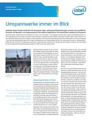
2. Hardware OverviewThe <strong>IA</strong>-<strong>PC</strong> <strong>HPET</strong> Architecture defines a set of timers that can be used by the operating system. The timersare defined such that in the future, the OS may be able to assign specific timers to be used directly byspecific applications. Each timer can be configured to generate a separate interrupt. This specificationallows for a block of 32 timers, with support for up to 8 blocks, for a total of 256 timers. However, specificimplementations can include only a subset of these timers.The timers are implemented as a single up-counter with a set of comparators. The counter increasesmonotonically. When software does two consecutive reads of the counter, the second read will never returna value that is less than the first read unless the counter has actually rolled over. Each timer includes amatch register and a comparator. Each individual timer can generate an interrupt when the value in itsmatch register equals the value of the free-running counter. Some of the timers can be enabled to generatea periodic interrupt.The registers associated with these timers are mapped to memory space (much like the I/O APIC).However, it is not implemented as a standard <strong>PC</strong>I function. The BIOS reports to the operating system thelocation of the memory-mapped register space consumed by the timers. The hardware can support relocatableaddress decode space, however the BIOS will set this space prior to handing it over to the OS. Itis not expected that the OS will move the location of these timers once it is set by the BIOS.ClockGen64/32 BitUp CounterCurrent_Count64/32 BitCompareC0=32 BitCompareC132 BitCompare=C2=Data Bus32 BitAdderIRQ En &Status Reg8254RTCFSBSticky BitsEnable BitsConfig/Enable/Status RegsCounter RegisterCompare RegistersInterrupt Routing Logic> All registers are memory-mapped> Multimedia Timer Subsystem is exposed to OSusing ACPI TablesINTI[X:Y]INTI_8INTI_2IRQ8IRQ0IOAPIC8259IOAPICLegacyCPUPeriod RegisterFigure 1 Hardware Block Diagram______________________________________________________________________________________<strong>IA</strong>-<strong>PC</strong> <strong>HPET</strong> <strong>Specification</strong> Rev <strong>1.0a</strong> 7
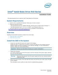
2.1 Register Model Overview2.1.1 Memory MapThe <strong>Event</strong> Timer registers are memory mapped in a non-indexed scheme. This allows the CPU to directlyaccess each register without having to use an index register. The timer register space is 1024 bytes. Theregisters are generally aligned on 64-bit boundaries to simplify implementation with <strong>IA</strong>64 processors. For<strong>IA</strong>64 platform, the timer register space can be up to 64K bytes with page protection capability. The registermodel allows each timer block to contain up to 32 timers, where each ‘timer’ consists of a comparator plusa match register.Register Model& Programming Interface63 0General Capabilities IDGeneral ConfigurationGeneral IRQ StatusMemoryMappedIOInterface‘Main’ Counter ( 32 or 64bit)BIOS BARTimerRegisters(1K)T0_Config_&_ CapsT0_ComparatorT0_FSB_IRQ_Routing> BIOS selects 1 of Nlocation in system memory> BIOS reports Base Addressof Timer Reg Block viaACPI Tables and ASL Code> Base Address can be4K aligned Memory-Mapped 64-bit Aligned Extensible Allows up to 32 <strong>Timers</strong> to be supported Capabilities Registers are Read Only Configuration Registers are R/WT31_Config_&_ CapsT31_ComparatorT31_FSB_IRQ_RoutingFigure 2 Register Model Overview______________________________________________________________________________________<strong>IA</strong>-<strong>PC</strong> <strong>HPET</strong> <strong>Specification</strong> Rev <strong>1.0a</strong> 8
2.2 Minimum Recommended Hardware ImplementationItem Recommendation CommentsMain CounterMain Counter WidthRequired to be an upcounter64-bitsClock FrequencyClock Frequency DriftFmin = 10 MHz+- .05 % (500 ppm )+- .2 % (2000 ppm)Over any interval >= 1 MillisecondOver any interval
2.3 Register Definitions2.3.1 Register OverviewOffset Register Type000-007h General Capabilities and ID Register Read Only008-00Fh Reserved010-017h General Configuration Register Read-Write018-01Fh Reserved020-027h General Interrupt Status Register Read/Write Clear028-0EFh Reserved0F0-0F7h Main Counter Value Register Read/Write0F8-0FFh Reserved100-107h Timer 0 Configuration and Capability Register Read/Write108-10Fh Timer 0 Comparator Value Register Read/Write110-117h Timer 0 FSB Interrupt Route Register Read/Write118-11Fh Reserved120-127h Timer 1 Configuration and Capability Register Read/Write128-12Fh Timer 1 Comparator Value Register Read/Write130-137h Timer 1 FSB Interrupt Route Register Read/Write138-13Fh Reserved140-147h Timer 2 Configuration and Capability Register Read/Write148-14Fh Timer 2 Comparator Value Register Read/Write150-157h Timer 2 FSB Interrupt Route Register Read/Write158-15Fh Reserved160-3FFh Reserved for <strong>Timers</strong> 3-31Table 2 Memory-Mapped Registers2.3.2 Programming Requirements1. Software must not attempt to read or write across register boundaries. For example, a 32-bit accessmust be to offset 00h, 04h, 08h, or 0Ch. 32-bit accesses must not be to 01h, 02h, 03h, 05h, 06h, 07h,09h, 0Ah, 0Bh, 0Dh, 0Eh, or 0Fh. 64-bit accesses can only be to 00h or 08h and must not cross 64-bitboundaries.2. Software should not write to read-only registers.3. Software should not expect any particular or consistent value when reading reserved registers or bits.4. Software should perform read-modify-write operations on reserved bits.Note:Host controllers are not required to support exclusive-access mechanisms (such as <strong>PC</strong>ILOCK) for accesses to the memory-mapped register space. Therefore, if software attemptsexclusive-access mechanisms to the host controller memory-mapped register space, theresults are undefined.2.3.3 Power Management ConsiderationsIt is the Operating System’s responsibility to save and restore <strong>Event</strong> Timer hardware context if this needs tobe preserved through ACPI System Sleep State transitions.General behavioral rules for <strong>Event</strong> Timer hardware regarding sleep state transitions:1. The <strong>Event</strong> Timer registers (including the main counter) are not expected to be preserved through anS3, S4, or S5 state.______________________________________________________________________________________<strong>IA</strong>-<strong>PC</strong> <strong>HPET</strong> <strong>Specification</strong> Rev <strong>1.0a</strong> 10
2. The features and functions associated with these registers are not expected to be used in an S1 state.Prior to going to an S1 state, all interrupts associated with this function should be disabled.3. The main counter is permitted, but not required, to run during S1 or S2 states. This allows mobilesystems to stop clock generators feeding the main counter during S1 or S2 states.2.3.4 General Capabilities and ID Register63:32 31:16 15 14 13 12:8 7:0RREV_IDNUM_TIM_CA<strong>PC</strong>OUNT_SIZE_CAPReservedLEG_ROUTE_CAPVENDOR_IDCOUNTER_CLK_PERIODOffset: 00h R ReservedFigure 3 General Capability and ID RegisterGeneral Capability and ID Register AddressingOffset0x00AttributeRead-OnlySize64-bitsGeneral BehavioralRules1. Writes to this register should not be attempted by software.2. Software can read the various bytes in this register using 32-bit or 64-bit accesses. 32-bitaccesses can be done to offset 00h or 04h, but not to offsets 01h, 02h, 03h, 05h, 06h, or 07h. 64-bit accesses can only be done to 00h.General Capabilities and ID Register Bit DefinitionsBitDescription63:32 COUNTER_CLK_PERIOD Main Counter Tick Period: This read-only field indicates the period at whichthe counter increments in femptoseconds (10^-15 seconds). A value of 0 in thisfield is not permitted. The value in this field must be less than or equal to05F5E100h (10^8 femptoseconds = 100 nanoseconds). The resolution must be infemptoseconds (rather than picoseconds) in order to achieve a resolution of 50ppm.31:16 VENDOR_ID This read-only field will be the same as what would be assigned if this logic was a<strong>PC</strong>I function.15 LEG_RT_CAP LegacyReplacement Route Capable: If this bit is a 1, it indicates that thehardware supports the LegacyReplacement Interrupt Route option.14 Reserved: In order to preserve usage of these bits in the future, software should always writea 0 to these bits until they are defined.13 COUNT_SIZE_CAP Counter Size:• This bit is a 0 to indicate that the main counter is 32 bits wide (andcannot operate in 64-bit mode).• This bit is a 1 to indicate that the main counter is 64 bits wide (although______________________________________________________________________________________<strong>IA</strong>-<strong>PC</strong> <strong>HPET</strong> <strong>Specification</strong> Rev <strong>1.0a</strong> 11
this does not preclude it from being operated in a 32-bit mode).12:8 NUM_TIM_CAP Number of <strong>Timers</strong>: This indicates the number of timers in this block. Thenumber in this field indicates the last timer (i.e. if there are three timers, the valuewill be 02h, four timers will be 03h, five timers will be 04h, etc.).7:0 REV_ID This indicates which revision of the function is implemented. The value mustNOT be 00h.2.3.5 General Configuration Register63:16 15:8 7:21 0RRRENABLE_CNFLEG_RT_CNFReservedReserved for ManufacturerReservedOffset: 00hRReservedFigure 4 General Configuration RegisterGeneral Configuration Register AddressingOffset0x10AttributeRead-WriteSize64-bitsGeneral Behavioral 1. Software can access the various bytes in this register using 32-bit or 64-bit accesses. 32-bitRulesaccesses can be done to offset 010h or 014h, but not to offsets 011h, 012h, 013h, 015h, 016h, or017h. 64-bit accesses can only be done to 010h.General Configuration Register Bit DefinitionsBitDescription63:16 Reserved In order to preserve usage of these bits in the future, software should not modify the value inthese bits until they are defined. This is done by doing a “read-modify-write” to thisregister.15:8 Reserved for Non-OSThese bits are reserved for the manufacturer. Future revisions of this spec will not use thesebits. OS-based drivers must not modify the value in these bits. This is done by doing a“read-modify-write” to this register.7:2 Reserved: In order to preserve usage of these bits in the future, software should not modify the value inthese bits until they are defined. This is done by doing a “read-modify-write” to thisregister.1 LEG_RT_CNF LegacyReplacement Route:• 0 – Doesn’t support LegacyReplacement Route• 1 – Supports LegacyReplacement RouteIf the ENABLE_CNF bit and the LEG_RT_CNF bit are both set, then the interrupts will berouted as follows:______________________________________________________________________________________<strong>IA</strong>-<strong>PC</strong> <strong>HPET</strong> <strong>Specification</strong> Rev <strong>1.0a</strong> 12
Timer 0 will be routed to IRQ0 in Non-APIC or IRQ2 in the I/O APICTimer 1 will be routed to IRQ8 in Non-APIC or IRQ8 in the I/O APICTimer 2-n will be routed as per the routing in the timer n config registers.If the LegacyReplacement Route bit is set, the individual routing bits for timers 0 and 1(APIC or FSB) will have no impact.If the LegacyReplacement Route bit is not set, the individual routing bits for each of thetimers are used.0 ENABLE_CNF Overall Enable: This bit must be set to enable any of the timers to generate interrupts. Ifthis bit is 0, then the main counter will halt (will not increment) and no interrupts will becaused by any of these timers.• 0 – Halt main count and disable all timer interrupts• 1 – allow main counter to run, and allow timer interrupts if enabled______________________________________________________________________________________<strong>IA</strong>-<strong>PC</strong> <strong>HPET</strong> <strong>Specification</strong> Rev <strong>1.0a</strong> 13
2.3.6 General Interrupt Status Register63:32 31:321 0RRT0_INT_STST1_INT_STST2_INT_STSReservedReservedOffset: 20h R ReservedFigure 5 General Interrupt Status RegisterGeneral Interrupt Status Register AddressingOffset020hAttributeRead-Write ClearSize64-bitsGeneral Behavioral 1. Software can access the various bytes in this register using 32-bit or 64-bit accesses. 32-bitRulesaccesses can be done to offset 20h or 24h, but not to offsets 21h, 22h, 23h, 25h, 26h, or 27h. 64-bit accesses can only be done to offset 20h.General Interrupt Status Register Field DefinitionsBit Field Name Description63:32 Reserved In order to preserve usage of these bits in the future, software should always write a 0 tothese bits until they are defined.31:3 Tn_INT_STS Timer n Interrupt Active (where xx is 31:3): Same functionality as for Timer 02 T2_INT_STS Timer 2 Interrupt Active: Same functionality as Timer 0.1 T1_INT_STS Timer 1 Interrupt Active: Same functionality as Timer 0.0 T0_INT_STS Timer 0 Interrupt Active: The functionality of this bit depends on whether the edge orlevel-triggered mode is used for this timer:If set to level-triggered mode:This bit defaults to 0. This bit will be set by hardware if the corresponding timerinterrupt is active. Once the bit is set, it can be cleared by software writing a 1to the same bit position. Writes of 0 to this bit will have no effect. For example,if the bit is already set a write of 0 will not clear the bit.If set to edge-triggered mode:This bit should be ignored by software. Software should always write 0 to this bit.Note: Software uses Tn_INT_TYPE_CNF bit (bit of Timer N Configuration and Capability Register)to select Level vs Edge operation.______________________________________________________________________________________<strong>IA</strong>-<strong>PC</strong> <strong>HPET</strong> <strong>Specification</strong> Rev <strong>1.0a</strong> 14
2.3.7 Main Counter Register630Counter valueOffset: 0F0hFigure 6 Main Counter RegisterMain Counter Register AddressingOffset0F0hAttributeRead/WriteSize64-bitsGeneral Behavioral 1. Software can access the various bytes in this register using 32-bit or 64-bit accesses. 32-bitRulesaccesses can be done to offset 0F0h or 0F4h. 64-bit accesses can be done to 0F0h. 32-bitaccesses must not be done starting at: 0F1h, 0F2h, 0F3h, 0F5h, 0F6h, or 0F7h.2. Writes to this register should only be done while the counter is halted.3. Reads to this register return the current value of the main counter.4. 32-bit counters will always return 0 for the upper 32-bits of this register.5. If 32-bit software attempts to read a 64-bit counter, it must be aware of timer rollover. Seesection 2.4.7 for details on safely accessing 64-bit counters using software or hardware whichonly supports 32-bit accesses. It is strongly recommended that 32-bit software only operate thetimer in 32-bit mode.6. Reads to this register are monotonic. No two consecutive reads will return the same value,except when the reads happen at less than the resolution of the counter or if the counter hasrolled over. (See section 2.4.1)Main Counter Register Field DefinitionsBit Field Name Description63:0 MAIN_COUNTER_VAL Bits 63:0 of the counter.______________________________________________________________________________________<strong>IA</strong>-<strong>PC</strong> <strong>HPET</strong> <strong>Specification</strong> Rev <strong>1.0a</strong> 15
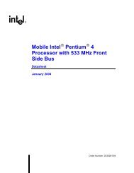
2.3.8 Timer N Configuration and Capabilities Register63:32 31:1615 14 13:9 87 6 5 4 3 21 0RRRReservedTN_INT_TYPE_CNFTN_INT_ENB_CNFTN_TYPE_CNFTN_PER_INT_CAPTN_SIZE_CAPTN_VAL_SET_CNFReservedTN_32MODE_CNFTN_INT_ROUTE_CNFTN_FSB_EN_CNFTN_FSB_INT_DEL_CAPReservedTN_INT_ROUTE_CAPOffset: 0100h(20h*N) + 100hRReservedFigure 7 Timer N Configuration and Capability RegisterT0_FSB_ENMainCounterCompare=Overall EnableENABLE_CNFLEG_RT_ENFSBIRQRouterFSBTimer 0ComparatorRegisterT0_INT_ENBAPICIRQRouterIOAPICCPU8254MUXINTI#2IRQ0IOAPICPICExample of Timer 0 Configuration and Capacities Diagram______________________________________________________________________________________<strong>IA</strong>-<strong>PC</strong> <strong>HPET</strong> <strong>Specification</strong> Rev <strong>1.0a</strong> 16
Timer N Configuration and Capability Register AddressingOffset Timer 0: 100h – 107h, Timer 1: 120h – 127h, Timer 2: 140h – 147hTimer n: (20h * n) + 100h through (20h * n) + 107hAttributeRead-WriteSize64-bitsGeneral Behavioral 1. Software can access the various bytes in this register using 32-bit or 64-bit accesses. 32-bitRulesaccesses can be done to offset 1x0h or 1x4h. 64-bit accesses can be done to offset 1x0h. 32-bitaccesses must not be done to offsets 1x1h, 1x2h, 1x3h, 1x5h, 1x6h, or 1x7h.2. Reads or writes to unimplemented timers should not be attempted.Timer N Configuration and Capability Register Field DefinitionsBit Field Name Description64:32 Tn_INT_ROUTE_CAP Timer n Interrupt Routing Capability: (where n is the timer number: 00 to31) This 32-bit read-only field indicates to which interrupts in the I/O (x) APICthis timer’s interrupt can be routed. This is used in conjunction with theTn_INT_ROUTE_CNF field.Each bit in this field corresponds to a particular interrupt. For example, if thistimer’s interrupt can be mapped to interrupts 16, 18, 20, 22, or 24, then bits 16,18, 20, 22, and 24 in this field will be set to 1. All other bits will be 0.31:16 Reserved In order to preserve usage of these bits in the future, software should alwayswrite a 0 to these bits until they are defined.15 Tn_FSB_INT_DEL_CAPTimer n FSB Interrupt Delivery: (where n is the timer number: 00 to 31). Ifthis read-only bit is 1, then the hardware supports a direct front-side bus deliveryof this timer’s interrupt.14 Tn_FSB_EN_CNF Timer n FSB Interrupt Enable: (where n is the timer number: 00 to 31). If theTn_FSB_INT_DEL_CAP bit is set for this timer, then the software can set theTn_FSB_EN_CNF bit to force the interrupts to be delivered directly as FSBmessages, rather than using the I/O (x) APIC. In this case, theTn_INT_ROUTE_CNF field in this register will be ignored. TheTn_FSB_ROUTE register will be used instead.13:9 Tn_INT_ROUTE_CNF Timer n Interrupt Route: (where n is the timer number: 00 to 31). This 5-bitread/write field indicates the routing for the interrupt to the I/O APIC. Amaximum value of 32 interrupts are supported. Default is 00h Software writesto this field to select which interrupt in the I/O (x) will be used for this timer’sinterrupt. If the value is not supported by this prarticular timer, then the valueread back will not match what is written. The software must only write validvalues.Note: If the LegacyReplacement Route bit is set, then <strong>Timers</strong> 0 and 1 will havea different routing, and this bit field has no effect for those two timers.Note: If the Tn_FSB_INT_DEL_CNF bit is set, then the interrupt will bedelivered directly to the FSB, and this bit field has no effect.8 Tn_32MODE_CNF Timer n 32-bit Mode: (where n is the timer number: 00 to 31). Software canset this read/write bit to force a 64-bit timer to behave as a 32-bit timer. This istypically needed if the software is not willing to halt the main counter to read orwrite a particular timer, and the software is not capable of doing an atomic 64-bit read to the timer. If the timer is not 64 bits wide, then this bit will always beread as 0 and writes will have no effect.7 Reserved In order to preserve usage of these bits in the future, software should alwayswrite a 0 to these bits until they are defined.6 Tn_VAL_SET_CNF Timer n Value Set: (where n is the timer number: 00 to 31). Software uses thisread/write bit only for timers that have been set to periodic mode. By writingthis bit to a 1, the software is then allowed to directly set a periodic timer’saccumulator.Software does NOT have to write this bit back to 0 (it automatically clears).______________________________________________________________________________________<strong>IA</strong>-<strong>PC</strong> <strong>HPET</strong> <strong>Specification</strong> Rev <strong>1.0a</strong> 17
Software should not write a 1 to this bit position if the timer is set to nonperiodicmode.5 Tn_SIZE_CAP Timer n Size: (where n is the timer number: 00 to 31). This read-only fieldindicates the size of the timer. 1 = 64-bits, 0 = 32-bits.4 Tn_PER_INT_CAP Timer n Periodic Interrupt Capable: (where n is the timer number: 00 to31). If this read-only bit is 1, then the hardware supports a periodic mode forthis timer’s interrupt.3 Tn_TYPE_CNF Timer n Type: (where n is the timer number: 00 to 31).If the corresponding Tn_PER_INT_CAP bit is 0, then this bit will alwaysreturn 0 when read and writes will have no impact.If the corresponding Tn_PER_INT_CAP bit is 1, then this bit is read/write, andcan be used to enable the timer to generate a periodic interrupt.• Writing a 1 to this bit enables the timer to generate a periodicinterrupt.• Writing a 0 to this bit enables the timer to generate a non-periodicinterrupt.2 Tn_INT_ENB_CNF Timer n Interrupt Enable: (where n is the timer number: 00 to 31). Thisread/write bit must be set to enable timer n to cause an interrupt when the timerevent fires.Note: If this bit is 0, the timer will still operate and generate appropriate statusbits, but will not cause an interrupt.1 Tn_INT_TYPE_CNF Timer n Interrupt Type: (where n is the timer number: 00 to 31)• 0 = The timer interrupt is edge triggered. This means that an edgetypeinterrupt is generated. If another interrupt occurs, another edgewill be generated.• 1 = The timer interrupt is level triggered. This means that a leveltriggeredinterrupt is generated. The interrupt will be held active untilit is cleared by writing to the bit in the General Interrupt StatusRegister. If another interrupt occurs before the interrupt is cleared, theinterrupt will remain active.0 Reserved In order to preserve usage of these bits in the future, software should alwayswrite a 0 to these bits until they are defined.______________________________________________________________________________________<strong>IA</strong>-<strong>PC</strong> <strong>HPET</strong> <strong>Specification</strong> Rev <strong>1.0a</strong> 18
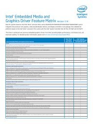
2.3.9 Timer N Comparator Register63:32 31:0TN Comparator ValueOffset: (20h * N) + 108hFigure 8 Timer N Comparator RegisterNon-Periodic Mode Operation:TN_Comparator Register ValueCounterCompareRegisterCompare=IRQPeriodic Mode Operation:TN_Comparator Register ValueMainCounterCompare+AdderComparatorRegister= IRQUpdate retgisterat match______________________________________________________________________________________<strong>IA</strong>-<strong>PC</strong> <strong>HPET</strong> <strong>Specification</strong> Rev <strong>1.0a</strong> 19
2.3.9.1 Register Definition and Usage ModelTimer N Comparator Register AddressingOffsetTimer 0: 108h – 10FhTimer 1: 128h – 12FhTimer 2: 148h – 14FhTimer n: (20h * n) + 108h - (20h * n) + 10FhAttributeRead-WriteSize64-bitsGeneral Behavioral 1. Software can access the various bytes in this register using 32-bit or 64-bit accesses. 32-bitRulesaccesses can be done to offset 1x8h or 1xCh. 64-bit accesses can be done to 1x8h. 32-bitaccesses must not be done to offsets 1x9h, 1xAh, 1xBh, 1xDh, 1xEh, or 1xFh.2. Reads to this register return the current value of the comparator.3. If the timer is configured to non-periodic mode:• Writes to this register load the value against which the main counter should be comparedfor this timer.• When the main counter equals the value last written to this register, the correspondinginterrupt can be generated (if so enabled).• The value in this register does not change based on the interrupt being generated.4. If the timer is configured to periodic mode:• When the main counter equals the value last written to this register, the correspondinginterrupt can be generated (if so enabled).• After the main counter equals the value in this register, the value in this register is increasedby the value last written to the register.For example, if the value written to the register is 00000123h, then1. An interrupt will be generated when the main counter reaches 00000123h.2. The value in this register will then be adjusted by the hardware to 00000246h.3. Another interrupt will be generated when the main counter reaches 00000246h4. The value in this register will then be adjusted by the hardware to 00000369h• As each periodic interrupt occurs, the value in this register will increment. When theincremented value is greater than the maximum value possible for this register(FFFFFFFFh for a 32-bit timer or FFFFFFFFFFFFFFFFh for a 64-bit timer), the value willwrap around through 0. For example, if the current value in a 32-bit timer is FFFF0000hand the last value written to this register is 20000, then after the next interrupt the valuewill change to 00010000h5. Default value for each timer is all 1’s for the bits that are implemented. For example, a 32-bittimer will have a default value of 00000000FFFFFFFFh. A 64-bit timer will have a defaultvalue of FFFFFFFFFFFFFFFFh.______________________________________________________________________________________<strong>IA</strong>-<strong>PC</strong> <strong>HPET</strong> <strong>Specification</strong> Rev <strong>1.0a</strong> 20
2.3.9.2 Periodic vs. Non-Periodic Modes2.3.9.2.1 Non-Periodic ModeThis mode change can be thought of as creating a one-shot timer.When a timer is set up for non-periodic mode, it will generate a value in the main counter that matches thevalue in the timer’s comparator register. If the timer is set up for 32-bit mode, then it will generate anotherinterrupt when the main counter wraps around.During run-time, the value in the timer’s comparator value register will not be changed by the hardware.Software can of course change the value.WARNING: Software developers must be careful when programming the comparator registers. If thevalue written to the register is not sufficiently set far enough ahead of the current register value, then thecounter may pass the value before it reaches the register and the interrupt will be missed.Every timer is required to support the non-periodic mode of operation.2.3.9.2.2 Periodic ModeWhen a timer is set up for periodic mode, the software writes a value in the timer’s comparator valueregister. When the main counter value matches the value in the timer’s comparator value register, aninterrupt can be generated. The hardware will then automatically increase the value in the comparatorvalue register by the last value written to that register.To make the periodic mode work properly, the main counter is typically written with a value of 0 so thatthe first interrupt occurs at the right point for the comparator. If the main counter is not set to 0, interruptsmay not occur as expected.During run-time, the value in the timer’s comparator value register can be read by software to find outwhen the next periodic interrupt will be generated (not the rate at which it generates interrupts). Softwareis expected to retain the last value written to the comparator’s value register (the rate at which interrupts aregenerated).If software wants to change the periodic rate, it should write a new value to the comparator value register.At the point when the timer’s comparator indicates a match, this new value will be added to derive the nextmatching point. So as to avoid race conditions where the new value is written just as a match occurs,either the main counter should be halted or the comparator disabled when the new periodic rate is written.If the software resets the main counter, the value in the comparator’s value register needs to reset as well.This can be done by setting the Tn_VAL_SET_CNF bit. Again, to avoid race conditions, this should bedone with the main counter halted. The following usage model is expected:1) Software clears the GLOBAL_ENABLE_CNF bit to prevent any interrupts2) Software Clears the main counter by writing a value of 00000000h to it.3) Software sets the TIMER0_VAL_SET_CNF bit.4) Software writes the new value in the TIMER0_COMPARATOR_VAL register5) Software sets the GLOBAL_ENABLE_CNF bit to enable interrupts.______________________________________________________________________________________<strong>IA</strong>-<strong>PC</strong> <strong>HPET</strong> <strong>Specification</strong> Rev <strong>1.0a</strong> 21
2.3.9.2.3 Read/Write Paths for Periodic Mode Vs One-Shot ModeOne-Shot Mode of OperationClockGenN-bit BitUp CounterN- BitCompareT0_C=IRQN- BitCompareT1_C=IRQData BusRead/WriteRead/WriteRead/WritePeriodic Mode of OperationClockGenN-bit BitUp CounterN BitAdderT0_C=IRQData BusRead/WriteWritesReadsFigure 9 Read/Write paths for One-shot Vs Periodic modes of operationFor <strong>Event</strong> <strong>Timers</strong> that provide hardware support (i.e. the adder logic) for periodic mode of operation, theTimer N Comparator Register is overloaded as shown in Figure 9. In the periodic mode of operation, writesto this register will program the periodic interval value to be added to the contents of the match register atthe next interrupt. Reads from this register will return the current contents of the match register at which thenext interrupt will occur.If it is necessary to save/restore the context of a periodic timer through ACPI Sleep state transitions, systemsoftware is expected to ‘remember’ the last value written to this register.______________________________________________________________________________________<strong>IA</strong>-<strong>PC</strong> <strong>HPET</strong> <strong>Specification</strong> Rev <strong>1.0a</strong> 22
2.3.10 Timer N FSB Interrupt Route Register63:32 31:0TN_FSB_INT_VALTN_FSB_INT_ADDROffset: (20h * N) + 110hFigure 10 Timer N FSB Interrupt Route RegisterOffset Timer 0: 110h – 117h,Timer 1: 130h – 137h,Timer 2: 150h – 157hTimer n: (20h * n) + 110h - (20h * n) + 117hAttributeRead-WriteSizeGeneral BehavioralRules64-bits1. Software can access the various bytes in this register using 32-bit or 64-bit accesses. 32-bitaccesses can be done to offset 1x0h or 1x4h. 64-bit accesses can be done to 1x0h. 32-bitaccesses must not be done to offsets 1x1h, 1x2h, 1x3h, 1x5h, 1x6h, or 1x7h.2. Reads or writes to unimplemented timers should not be attempted.Bit Field Name Description64:32 Tn_FSB_INT_ADDR Software sets this 32-bit field to indicate the location that the FSB interruptmessage should be written to.31:0 Tn_FSB_INT_VAL Software sets this 32-bit field to indicate that value that is written during the FSBinterrupt message2.4 Theory Of Operation2.4.1 Timer Accuracy Rules1. The timers are expected to be accurate over any 1 ms period to within 0.05% (500 ppm)of the timespecified in the timer resolution fields.2. Within any 100-microsecond period, the timer is permitted to report a time that is up to 2 ticks tooearly or too late. Each tick must be less than or equal to 100 ns, so this represents an error of less than0.2% (2000 ppm).3. The main counter must be an up-counter. Two consecutive reads to the main counter may return thesame value if the access latency to the timer is less than the clock period that feeds it. For back-backreads, the 2 nd read must never return a value that is less than the 1 st read, unless the counter has rolledover and actually reached the same value.______________________________________________________________________________________<strong>IA</strong>-<strong>PC</strong> <strong>HPET</strong> <strong>Specification</strong> Rev <strong>1.0a</strong> 23
2.4.2 Interrupt MappingThe interrupts associated with the various timers have several interrupt mapping options.2.4.2.1 Mapping Option #1: LegacyReplacement OptionIf the Legacy Replacement Route bit (LEG_RT_CNF) is set (‘1’), the following mapping is forced:Timer 8259 Mapping APIC Mapping Comment0 IRQ0 IRQ2 In this case, the 8254 timer will not cause any interrupts1 IRQ8 IRQ8 In this case, the RTC will not cause any interrupts.2 As per IRQRouting FieldAs per IRQ RoutingField2.4.2.2 Mapping Option #2: Standard OptionIf the LegacyReplacement Route bit (LEG_RT_CNF) is clear (‘0’), each timer has its own routing control.The interrupts can be routed to various interrupts in the I/O APIC. A capability field indicates whichinterrupts are valid options for the routing.If a timer is set for edge-triggered mode, the timers should not be shared with any <strong>PC</strong>I interrupts.2.4.2.3 Mapping Option #3: FSB OptionIn this case, the interrupts are mapped directly to the FSB interrupts without going to the 8259 or I/O (x)APIC. To use this mode, the interrupt must be configured to edge-triggered mode. A separate configurebit must be set to enable this mode.When the interrupt is delivered to the FSB, the message is delivered to the address indicated in theTn_FSB_INT_ADDR field. The data value for the write cycle is specified in the Tn_FSB_INT_VALfield.Notes:• The FSB interrupt deliver option has HIGHER priority and is mutually exclusive to the standardinterrupt delivery option. Thus, if the Tn_FSB_EN_CNF bit is set, the interrupts will be delivered viathe FSB, rather than via the APIC or 8259.• The FSB interrupt delivery can be used even when the LegacyReplacement mapping is used.2.4.3 Periodic vs. Non-Periodic Modes2.4.3.1 Non-Periodic ModeThis mode of operation provides a one-shot timer.When a timer is set for non-periodic mode, it will generate an interrupt when the value in the main countermatches the value in the timer’s comparator register. If the timer is set up for 32-bit mode, then it willgenerate another interrupt when the main counter wraps around.During run-time, the value in the timer’s comparator value register will not be changed by the hardware.Software can of course change the value.WARNING:______________________________________________________________________________________<strong>IA</strong>-<strong>PC</strong> <strong>HPET</strong> <strong>Specification</strong> Rev <strong>1.0a</strong> 24
Software developers must be careful when programming the comparator registers. If the value written tothe register is not sufficiently set far enough ahead of the current register value, then the counter may passthe value before it reaches the register and the interrupt will be missed.Every timer is required to support the non-periodic mode of operation.2.4.3.2 Periodic ModeWhen a timer is set for periodic mode, the software writes a value in the timer’s comparator register. Whenthe main counter value matches the value in the timer’s comparator register, an interrupt can be generated.The hardware will then automatically increase the value in the compare register by the last value written tothat register.To make the periodic mode work properly, the main counter is typically written with a value of 0 so thatthe first interrupt occurs at the right point for the comparator. If the main counter is not set to 0, interruptsmay not occur as expected.During run-time, the value in the timer’s comparator value register can be read by software to find outwhen the next periodic interrupt will be generated.Software can also write to the comparator’s match register to select a different period. A write to theregister will not immediately be loaded into the comparator. It will only be added at the time thecomparator triggers.There is no mechanism to immediately change the periodic rate.Each timer is NOT required to support this mode of operation. A capabilities bit indicates if the particulartimer supports periodic mode. The reason for this is that supporting the periodic mode adds a significantamount of gates.2.4.4 Enabling the <strong>Timers</strong>The BIOS or OS PnP code should:1. Assign Base Address to each Timer Block in the System.2. Route the interrupts. This includes the LegacyReplacement Route bit, Interrupt Route bit (for eachtimer), interrupt type (to select the edge or level type for each timer).3. If system BIOS is used to enable the timers, then report memory and interrupt resources consumed byeach Timer Block to OS Configuration Manager using <strong>HPET</strong>.The Device Driver code should do the following for an available timer:1. Set the timer type field (selects one-shot or periodic).2. Set the interrupt enable3. Set the comparator match4. Set the Overall Enable bit (Offset 04h, bit 0). This starts the main counter and enables comparators todeliver interrupts.2.4.5 Interrupt LevelsThe interrupts are all active high.If the interrupts are mapped to the I/O APIC and set for level-triggered mode, they can be shared with <strong>PC</strong>Iinterrupts.______________________________________________________________________________________<strong>IA</strong>-<strong>PC</strong> <strong>HPET</strong> <strong>Specification</strong> Rev <strong>1.0a</strong> 25
2.4.6 Handling InterruptsIf each timer has a unique interrupt and the timer has been configured for edge-triggered mode, then thereare no specific steps required. No read is required to process the interrupt.If a timer has been configured to level-triggered mode, then its interrupt must be cleared by the software.This is done by reading the interrupt status register and writing a 1 back to the bit position for the interruptto be cleared.Independent of the mode, software can read the value in the main counter to see how much time has passedfrom when the interrupt was generated and when it was first serviced.If a timer is set up to generate a periodic interrupt, the software can check to see how much time remainsuntil the next interrupt by reading the main counter.2.4.7 Issues related to 64-bit <strong>Timers</strong> with 32-bit CPUsA 32-bit timer can be read directly using processors that are capable of 32-bit or 64-bit instructions.However, a 32-bit processor may not be able to directly read a 64-bit timer. A race condition comes up if a32-bit CPU reads the 64-bit register using two separate 32-bit reads. An accuracy problem may be arise ifjust after reading one half, the other half rolls over and changes the first half.Software has several ways of reading the 64 bit counter using 32 bit reads. The first is that it may halt thecounter, read the high and low 32 bits, and then restart the counter. This has the obvious drawback ofshifting the counter timebase.If software does not want to halt the timer, it can use the 64-bit timer as a 32-bit timer by setting theTIMERn_32MODE_CNF bit. This will cause the timer to behave as a 32-bit timer. The upper 32-bits willalways be 0.Alternatively, software may do a multiple read of the counter while it is running. Software can read thehigh 32 bits, then the low 32 bits, then the high 32 bits again. If the high 32 bits have not changed betweenthe two reads, then a rollover has not happened and the low 32 bits are valid. If the high 32 bits havechanged between reads, then the multiple reads are repeated until a valid read is performed.Note: On a 64-bit platform, if software attempts a 64 bit read of the 64-bit counter, software mustbe aware that some platforms may break the 64 bit read into two 32 bit reads, and therefore theread may be inaccurate if the low 32 bits roll over between the high and low part reads.______________________________________________________________________________________<strong>IA</strong>-<strong>PC</strong> <strong>HPET</strong> <strong>Specification</strong> Rev <strong>1.0a</strong> 26
3. Enumeration & Configuration of <strong>HPET</strong>Operating System software must discover/configure platform timers early in the OS boot process.Typically, the OS has to establish basic timer services before it can begin loading drivers. This requiresenumeration of timer hardware to be handled by system BIOS tables (ie ACPI Tables) versus ACPI namespace. System Resources consumed by the <strong>Event</strong> Timer hardware (memory and interrupts) should bereported by the System BIOS using ACPI Name space.3.1 Initial State of <strong>Event</strong> Timer Hardware• Main Counter is Halted and Zeroed• Comparator Match Registers reset to all 1’s.• All interrupts are disabled• General Configuration and Capability Register [Offset 0x010] = 00• Global IRQ Enable bit comes up disabled…no comparators can deliver interrupts• LegacyReplacement IRQ Routing Enable bit comes up disabled…8254 is on IRQ0, RTC ison IRQ83.2 BIOS Initialization3.2.1 Assign memory to Timer Block(s)Map each <strong>HPET</strong> (MMT) block to CPU memory space using implementation specific Base AddressRegisters. Each <strong>HPET</strong> block in the system will consume 1K of system memory.3.2.2 <strong>HPET</strong> Block Interrupt RoutingExcept for the case where <strong>HPET</strong> are being used to replace 8254/RTC functionality, all <strong>HPET</strong> interrupts aredisabled. The OS is responsible for establishing interrupt routing/delivery metrics prior to utilizing anygiven comparator within a Timer Block.3.2.2.1 Routing Interrupts for <strong>HPET</strong> Blocks that do not support 8254/RTC IRQ RoutingIn general, system BIOS is not required to assign or report <strong>HPET</strong> interrupts in system name space. ThePower-On-Default state of all compare interrupts should be disabled as shown in the following table.Device Interrupt Routing Comments8254 IRQ0, INTI2 8254 signals via PIC/APIC using IRQ0/INTI2 LegacyReplacement IRQ Routing Disabled for Comparator_0RTC IRQ8, INTI8 RTC signals via PIC/APIC using IRQ8/INTI8 LegacyReplacement IRQ Routing Disabled for Comparator_1Compare 0 INTI [xx] BIOS leaves Disabled OS responsible for establishing irq routing prior to using this comparatorCompare 1 INTI [xx] BIOS leaves Disabled OS responsible for establishing irq metrics prior to using this comparatorCompare 2 INTI [xx] BIOS leaves Disabled OS responsible for establishing irq metrics prior to using this comparator……Compare 31 INTI [xx] BIOS leaves Disabled OS responsible for establishing irq metrics prior to using this comparator______________________________________________________________________________________<strong>IA</strong>-<strong>PC</strong> <strong>HPET</strong> <strong>Specification</strong> Rev <strong>1.0a</strong> 27
3.2.2.2 Routing Interrupts for <strong>HPET</strong> Blocks that support 8254/RTC IRQsThe exception to this rule is for the single <strong>HPET</strong> block in the system that may optionally support legacy8254 & LegacyReplacement RTC irq routings for the compare interrupts. Assuming platform does nothave 8254/RTC hardware or does not want to support this legacy timer hardware, for this case, SystemBIOS should set the LegacyReplacement Route bit and report IRQ0 & IRQ8 as being consumed by the<strong>HPET</strong> block in system name space:Device Interrupt Routing Comments8254 Not connected BIOS sets LegacyReplacement Route bit (LEG_RT_CNF)> LegacyReplacement IRQ Routing Enabled for Comparator_0• If present, 8254 will not cause any interrupts• If present, 8254 will still consume legacy i/o rangeRTC Not connected BIOS sets LegacyReplacement Route bit (LEG_RT_CNF)> LegacyReplacement IRQ Routing Enabled for Comparator_1• If present, RTC Periodic Interrupt Function will not cause any interrupts.• RTC Alarm function (still required) will signal interrupts via SCI• RTC CMOS function (still required) will consume i/o rangeCompare 0 IRQ0, INTI2 BIOS sets LegacyReplacement Route bit (LEG_RT_CNF)• Comparator_0 replaces 8254 PIT FunctionCompare 1 IRQ8, INTI8 BIOS sets LegacyReplacement Route bit (LEG_RT_CNF)• Comparator_0 replaces 8254 PIT FunctionCompare 2 INTI [xx]…Compare 31 INTI [xx]Note 1: The use of LegacyReplacement IRQ Routing for C0 & C1 does not preclude delivery ofIRQ0/IRQ8 via FSB.______________________________________________________________________________________<strong>IA</strong>-<strong>PC</strong> <strong>HPET</strong> <strong>Specification</strong> Rev <strong>1.0a</strong> 28
3.2.3 Considerations for Platforms without Legacy <strong>Timers</strong>If it is necessary to maintain DOS compatibility at INT 19 (or if necessary by OS to have periodic timerticks running when hand-over occurs from BIOS to OS for IPL), BIOS can use Timer_0 in periodic mode(Vs 8254).<strong>IA</strong>-<strong>PC</strong> <strong>HPET</strong> do not replace RTC Time of Day, RTC Alarm, and RTC CMOS functionality. <strong>IA</strong>-<strong>PC</strong>Multimedia <strong>Event</strong> Timer architecture supplements/replaces only the RTC Periodic Interrupt function.When the event timer is using IRQ8, RTC Alarm function will signal interrupts using SCI.IOAPICINTI_8SCILegacy IRQRoute EnableBit for Compare_XCX_IRQEnable BitIRQN BitCompare=Counter8259PICIRQ8SCI2:1 MuxIRQ8#CX_IRQStatus BitRTC PeriodicValue toCompareSCIRouterPM1_ENRegPM1_STSRegSleep/WakeSMRTC_ENRTC_STSRTC AlarmRTC TODI/O BasedIndex/DataInterfaceCMOS NVSFigure 11 RTC Functionality replaced by <strong>IA</strong><strong>PC</strong> <strong>HPET</strong>The <strong>IA</strong>-<strong>PC</strong> <strong>HPET</strong> Architecture switches on or off both the 8254 and the RTC Periodic Interrupt Functionstogether.For the platforms without Legacy <strong>Timers</strong>, System BIOS needs to mark the 8254 and RTC Periodicfunctions as ‘missing’ using the ACPI 2.0 proposed ‘legacy free’ flags.______________________________________________________________________________________<strong>IA</strong>-<strong>PC</strong> <strong>HPET</strong> <strong>Specification</strong> Rev <strong>1.0a</strong> 29
3.2.4 The ACPI 2.0 <strong>HPET</strong> Description Table (<strong>HPET</strong>)The <strong>HPET</strong> Description Table is a means to report the Base Addresses of each <strong>Event</strong> Timer Block early inthe OS boot process. The table is needed to allow Operating Systems to discover event timers and establishbasic timer services for driver load.Table 3 <strong>HPET</strong> Description TableFieldByteLengthdecimalByte OffsetdecimalDescriptionHeaderSignature 4 0 ‘<strong>HPET</strong>’. Signature for the <strong>HPET</strong> Description Table.Length 4 4 Length, in bytes, of the entire <strong>Event</strong> Timer DescriptionTable.Revision 1 8 The revision of the <strong>HPET</strong> Description Table definition;currently 01h.Checksum 1 9 Entire table must sum to zero.OEMID 6 10 OEM ID.OEM Table ID 8 16 For the <strong>Event</strong> Timer Description Table, the table ID is themanufacturer model ID.OEM Revision 4 24 OEM revision of <strong>Event</strong> Timer Description Table forsupplied OEM Table ID.Creator ID 4 28 Vendor ID of utility that created the table. For the DSDT,RSDT, SSDT, and PSDT tables, this is the ID for theASL Compiler.Creator Revision 4 32 Revision of utility that created the table. For the DSDT,RSDT, SSDT, and PSDT tables, this is the revision forthe ASL Compiler.<strong>Event</strong> Timer Block ID*Note #1BASE_ADDRESSLower 32-bit4 36 Hardware ID of <strong>Event</strong> Timer Block:Contents of General_Cap&ID Reg of Timer Block[31:16] = <strong>PC</strong>I Vendor ID of 1 st Timer Block[15] = LegacyReplacement IRQ Routing Capable[14] = Reserved[13] = COUNT_SIZE_CAP counter size[12:8] = Number of Comparators in 1 st Timer Block[7:0] = Hardware Rev ID12 40 The lower 32-bit base address of <strong>Event</strong> Timer Block.Each <strong>Event</strong> Timer Block consumes 1K of systemmemory, regardless of how many comparators areactually implemented by the hardware.*Note #2<strong>HPET</strong> Number 1 52 This one byte field indicates the <strong>HPET</strong> sequence number.0 = 1 st table, 1 = 2 nd table and so forth. This field iswritten by BIOS at boot time and should not be altered byany other software.Main Counter MinimumClock_tick in PeriodicMode*Note#32 53 Unit: Clock tickThe minimum clock ticks can be set without lostinterrupts while the counter is programmed to operate inperiodic mode______________________________________________________________________________________<strong>IA</strong>-<strong>PC</strong> <strong>HPET</strong> <strong>Specification</strong> Rev <strong>1.0a</strong> 30
FieldPage Protection And OEMAttributeByteLengthdecimalByte OffsetdecimalDescription1 55 The lower 4-bit ( bit ) of this field describes thetimer hardware capability to guarantee the pageprotection. This information is required for the OSes thatwant to expose this timer to the user space:0 = no guarantee for page protection.1 = 4KB page protected, access to the adjacent 3KBspace will not generate machine check orcompromise the system security.2 = 64KB page protected, access to the adjacent63KB space will not generate machine check orcompromise the system security.3~ 15 = Reserved for future use.The upper 4-bit (bits of this field is reserved forOEM attributes:OEM can use this field for its implementation specificattributes.*Note #1: This field provides a quick access for software which needs to know the <strong>HPET</strong> implementation.*Note #2: This is a 12-byte ACPI address format:GAS (Generic Address Structure) -- ACPI Address Format:Byte #1 – Address_Space_ID : 0 – System Memory1 – System I/OByte #2 – Register_Bit_WidthByte #3 – Register_Bit_OffsetByte #4 – ReservedByte #5 to 12 – 64-bit address* Note #3: This field is written by BIOS and may be chipset and/or platform dependent. This indicates theminimum value that must be used for any counter programmed in periodic mode to avoid lost interrupts. For anycounter x that has been configured for periodic mode, the number can be programmed in any Tx_CompareRegister must be greater than P, whereP = (Minimum Period) / (Main counter period) in order to avoid lost interrupts.* Note 4: The <strong>HPET</strong> Number field must match the number in the _UID field in the ACPI Namespace table(section 3.2.5.1) for the specific counter being described.For the case where there may be additional <strong>Event</strong> Timer Blocks implemented in the system, their baseaddresses would be described in ACPI Name space.Only one <strong>Event</strong> Timer Block needs to be described in the <strong>HPET</strong> in order to boot strap the OS.For “legacy free” platforms that do not implement the 8254 Timer/RTC Periodic Interrupt logic, the <strong>Event</strong>Timer Block described in the <strong>HPET</strong> would be the one that provides functionality to replace the 8254/RTCPeriodic Interrupt Logic.Object Description______________________________________________________________________________________<strong>IA</strong>-<strong>PC</strong> <strong>HPET</strong> <strong>Specification</strong> Rev <strong>1.0a</strong> 31
_HID_STR_CRSPAGEATTRNamed object that provides the interface’s Plug and Play identifier. This valueis set to PNP0103. _HID is a standard device configuration control methoddefined in ACPI 2.0 Spec section 6.1.4, "_HID (Hardware ID)."Named object (optional) that evaluates to a Unicode string that may be used byan OS to provide information to an end user describing the device. __STR is astandard device configuration control method defined in ACPI 2.0 Spec section6.1.5, "_STR (String)."Named object that returns the <strong>Event</strong> Timer’s current resource settings. <strong>Event</strong>Timer is considered static resources; hence only return its defined resources._CRS is a standard device configuration control method defined in ACPI 2.0 Spec section 6.2.1,"_CRS (Current Resource Settings)."Object that specifies the page protection capability, as defined in the <strong>HPET</strong>Description Table.Object that specifies the timer attributes, as defined in the <strong>HPET</strong>Description Table3.2.5 Describing <strong>Event</strong> Timer(s) in ACPI Name spaceSystem BIOS must report memory and interrupt resources consumed by each <strong>Event</strong> Timer block in ACPIName space.<strong>Event</strong> Timer(s) memory assignments are established by the system BIOS on per Timer Block basis. <strong>Event</strong>Timer(s) memory assignments are reported to the OS by the BIOS using <strong>HPET</strong> Table and in ACPI Namespace.<strong>Event</strong> Timer IRQ assignments need only be established for the single Timer Block that may optionallyprovide hardware support to supplement/replace legacy 8254 and legacy RTC hardware with these new<strong>HPET</strong>. For this case, system bios reports interrupt resources consumed by the Timer Block in ACPI Namespace. For the case where the Timer Block does not provide legacy 8254/legacy RTC hardwarereplacement, system bios is not required to establish or report <strong>Event</strong> Timer Interrupt assignments. The OSis expected to assign event timer interrupts prior to utilizing any given comparator in the Timer Block.PNP0103 is Microsoft assigned generic PNPID for <strong>IA</strong>-<strong>PC</strong> <strong>HPET</strong> blocks.3.2.5.1 ACPI Name Space ExampleDevice (<strong>HPET</strong>)_HID PNP0103 // newly assigned PNPID for <strong>IA</strong><strong>PC</strong> <strong>HPET</strong>_UID 0 // Optional : used if there are more than 1 timer blocks_CRS ( memory range consumed // Report 1K of memory consumed by this Timer BlockIRQs consumed ) // Optional : only used if BIOS allocates Interrupts 1Notes:1. For case where Timer Block is configured to consume IRQ0/IRQ8 AND Legacy 8254/Legacy RTC hardware stillexists, the device objects associated with 8254 & RTC devices should not report IRQ0/IRQ8 as “consumedresources.”2. If one or more <strong>HPET</strong> Description tables exist (see section 3.2.4), the _UID in the ACPI name space description forthe counter must correspond to the “<strong>HPET</strong> Number” field for the counter described in the in the <strong>HPET</strong> DescriptionTable(s).3.2.6 Recommendations for OS Initialization codeFrom ACPI <strong>HPET</strong> table, the OS initialization code extracts the base address assigned by the BIOS for eachtimer block implemented in the system. The OS initialization code can then directly query the timerhardware to discover detailed attributes and configurations supported by the timer hardwareimplementation.______________________________________________________________________________________<strong>IA</strong>-<strong>PC</strong> <strong>HPET</strong> <strong>Specification</strong> Rev <strong>1.0a</strong> 32
<strong>IA</strong>-<strong>PC</strong> <strong>HPET</strong> architecture has configuration and capability reporting mechanisms designed in at the registerlevel. OS initialization code can query these registers to determine, establish, or override (for example:default IRQ assignments established by the BIOS) <strong>Event</strong> Timer hardware configurations.The following registers provide enumeration info to system software:General Capabilities & ID RegisterOffset 00h• Clock Frequency• Width of Main Counter• Vendor ID/Hardware ID• LegacyReplacement Timer IRQ Routing Capable (or not)• Number of Comparator’s ImplementedTo determine / override the default IRQ assignments established by the BIOS:General Configuration RegisterOffset 04h• Global Interrupt Enable Bit• LegacyReplacement Timer IRQ Routing Enable BitTimer N Configuration & Capabilities Register1 for each Comparator implemented:Offsets:Timer 0: 108h – 10FhTimer 1: 128h – 12FhTimer 2: 148h – 14FhTimer n: (20h * n) + 108h - (20h * n) + 10Fh• Width of Comparator• Comparator Configuration bit which allows 64bit comparator to behave like a 32bitcomparator.• Per Comparator Interrupt Enable• Edge Vs Level selection• IOAPIC IRQ Routing capabilities reporting• IO APIC IRQ Router settings• FSB IRQ Delivery Capable (or not)• FSB IRQ Delivery Enable bit• Operating Modes : Periodic Vs One-ShotTimer_N_FSB_Route RegisterOffset: 1 for each Comparator Implemented• Address to which the FSB interrupt message should be written.• Data Value/Vector to be used with FSB interrupt message.______________________________________________________________________________________<strong>IA</strong>-<strong>PC</strong> <strong>HPET</strong> <strong>Specification</strong> Rev <strong>1.0a</strong> 33