LTFX Installation Manual - Chromalox Precision Heat and Control
LTFX Installation Manual - Chromalox Precision Heat and Control
LTFX Installation Manual - Chromalox Precision Heat and Control

Create successful ePaper yourself
Turn your PDF publications into a flip-book with our unique Google optimized e-Paper software.
<strong>LTFX</strong>Electric TankImmersion <strong>Heat</strong>ers<strong>Installation</strong> Instructions1PN403-4161-049178-101July 2013
<strong>LTFX</strong>Electric Tank Immersion <strong>Heat</strong>er <strong>Installation</strong> InstructionsGeneralThe <strong>Chromalox</strong> Electric Tank Immersion <strong>Heat</strong>er, Model<strong>LTFX</strong>, is an engineered, pretested package designed togive years of virtually maintenance free service <strong>and</strong> it isshipped ready for installation into a storage tank. <strong>LTFX</strong>provides low watt-density heating over a large heatingsurface with precise temperature control for suchmaterials as asphalt, fuel oil, pitch <strong>and</strong> tar, liquid sugar,lube oils, linseed oil, biodiesel, glycerin, ethanol <strong>and</strong>many other heat sensitive compounds.The open coil heating elements (OCE) are housed ineither 2” or 3” Schedule 40 carbon or stainless steelpipes, which are welded into the 150# ANSI flange.Once the Unitary Immersion <strong>Heat</strong>er is mated to yourtank, the heating elements may be removed <strong>and</strong> replacedwithout draining the tank.Since excessive temperatures may permanently damagethe heater <strong>and</strong> cause premature failure, the use oftemperature controls, limiting controls, <strong>and</strong> liquid levelsensors are required.The system designer is responsible for thesafety of this equipment <strong>and</strong> should install adequateback-up controls <strong>and</strong> safety deviceswith their electric heating equipment. Wherethe consequences of failure could result in personalinjury or property damage, back-up controlsare essential.<strong>Installation</strong>FIRE OR EXPLOSION HAZARD: The tank mustbe purged of all flammable vapors prior to cuttingor welding.High heating efficiency, low element temperatures, <strong>and</strong>longer heater life are achieved when the unit is properlyinstalled.1. To avoid chipping or cracking, precaution should betaken while unpacking, h<strong>and</strong>ling, <strong>and</strong> installing theceramic insulators. <strong>Heat</strong>ers with damaged insulatorsshould be returned to the factory for repair orreplacement. Contact your local sales office for returnauthorization.2. The <strong>LTFX</strong> unit must not be mounted in the verticalposition as the resistance wire on the OCE elementcan sag, thus causing uneven heating or short circuit.Unit should be installed in a horizontal positionwith the thermowell on top only.FIRE OR EXPLOSION HAZARD: Mount the heaterin a level, horizontal orientation only. Allother orientations may result in property damageor personal injury.3. IMPORTANT: Mount heater in the tank so the liquidlevel will always be above the effective heated portionof the heater. Provide expansion tank if necessary.4. Select a location for this installation according tothe following guidelines: (refer to Figure 1)A. <strong>Heat</strong>ing elements are removable through the terminalenclosure however adequate room mustbe provided for this purpose. The removal lengthof the OCE heating element is 3 feet since thecenter section may be bent on a 12” radius. OCEelements should only be bent in a vertical planewith ground strap on the bottom.B. The neck on the tank’s mating flange should beof adequate length to accommodate tank insulation<strong>and</strong> flange bolting.5. Tube supports (internal to the tank) should beplaced approximately three feet from the ‘wet-side’of the <strong>LTFX</strong> flange to ensure gasket sealing integrity.Additional tube supports can then be spaced on 10foot centers. Do not anchor the heater tubes to thesupports, as the tubes must be allowed to exp<strong>and</strong>.6. To ensure proper sealing, a material appropriategasket needs to be installed between the matingflanges. The mating flanges should then be securedby tightening the bolting according to TEMA St<strong>and</strong>ards.7. A tank suction pipe should be mounted at least 2”above the level of the heaters. A separate line canbe provided to drain tank after heaters have beende-energized.2
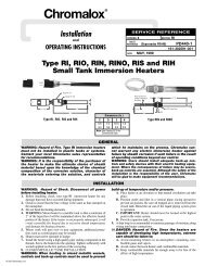
Allow for TankInsulation <strong>and</strong> Bolting36” Min. ElementRemoval DistanceFluidLevelOpen-Coil ElementsModel <strong>LTFX</strong>Figure 1WiringELECTRIC SHOCK HAZARD. Disconnect allpower before installing or servicing heater.Failure to do so could result in personal injuryor property damage. <strong>Heat</strong>er must be installedor serviced by a qualified person in accordancewith applicable National Electric Codes, NFPA70 <strong>and</strong>/or International Electric codes.ELECTRIC SHOCK HAZARD. Any installationinvolving electric heaters must be performedby a qualified person <strong>and</strong> must be effectivelygrounded in accordance with applicable NationalElectric Codes <strong>and</strong>/or International ElectricCodes to eliminate shock hazard.The system designer is responsible for thesafety of this equipment <strong>and</strong> should install adequateback-up controls <strong>and</strong> safety deviceswith their electric heating equipment. Wherethe consequences of failure could result in personalinjury or property damage, back-up controlsare essential.1. Electrical wiring to heating elements must be sized<strong>and</strong> installed in accordance with applicable NationalElectric Codes, International Electric Codes <strong>and</strong>/or<strong>and</strong> applicable local codes by a qualified person asdefined by the code.2. Temperatures at the heater terminals will require theuse of manganese nickel or equivalent temperaturelead wire. (Type TGS, TGT, or TGGT are recommended.)Wiring Entrance Locations - MoistureResistant Housing Only (E4 Option)The Moisture Resistant (E4) Housing offers severalconvenient options for conduit wiring & location. Thehousing is equipped with two removable service entranceplates for installation of wiring. Any or all of thesix sides can be used for wiring locations. Refer to explodedview drawing. The housing can also be rotated(by removal from flange) to allow for more positionpossibilities. To install service entrance holes, simplyremove the side Allen screws <strong>and</strong> use the centeringdepression to drill the appropriate size hole. Reinstallthe gasket(s), if applicable, <strong>and</strong> service entrance platesby tightening the Allen head screws to 4-5 in/lbs. The‘Octobox’ style of housing can be removed for ease ofaccess to element bussing or to better locate the powerconduit(s) entry point. To accomplish, simply removethe Allen-head screws on the outside of the housing.3
When reinstalling, be sure to properly align gasket, ifapplicable, <strong>and</strong> tighten to 40-50 in/lbs.Tip for Reinstalling Gaskets:Place allen head screws through metal covers <strong>and</strong>gentle push gasket hole over the threaded screw. Thiswill allow the gasket to stay in place while tighteningthe cover.Table A – E4 Wiring Information<strong>Heat</strong>er kW Volts PhaseTotalAmpsCircuits<strong>LTFX</strong>-125-004E4 4 480 3 4.8 1<strong>LTFX</strong>-128-008E4 8 480 3 9.6 1<strong>LTFX</strong>-1212-012E4 12 480 3 14.5 1<strong>LTFX</strong>-2212-024E4 24 480 3 28.9 1<strong>LTFX</strong>-3212-036E4 36 480 3 43.4 1<strong>LTFX</strong>-2325-060E4 60 480 3 72.3 1<strong>LTFX</strong>-3325-090E4 90 480 3 108.4 3<strong>LTFX</strong>-4325-120E4 120 480 3 144.5 2<strong>LTFX</strong>-6325-180E4 180 480 3 216.8 3<strong>LTFX</strong>-8325-240E4 240 480 3 289.0 4Wiring Entrance Locations - ExplosionResistant Housing Only (E2 Option)The Explosion Resistant (E2) Housing features dedicatedconduit connection sizes <strong>and</strong> locations for eitherNPT installation of conduit or Metric cable gl<strong>and</strong>s. Incomingwiring must be suitable for a maximum terminalenclosure temperature of 158˚F (70˚C). Wiring installationmust be in accordance with Hazardous Arearequirements. The use of EYS seals or rigid conduitmay be required. Please consult with the local inspectionauthority.Maximum TemperaturesSafe operation in a hazardous location requires themaximum operating temperatures of all exposed surfacesof the heater including temperatures on the outsideof the vessel, piping, flanges, screw plugs, enclosures<strong>and</strong> other heat conducting parts be limited. Theflammable liquids, vapors or gases present determinethe maximum surface temperature permitted in anyhazardous location. The end user or purchaser of theelectric heating equipment is responsible for determiningthe proper classification of an area <strong>and</strong> for providing<strong>Chromalox</strong> with hazardous area specifications <strong>and</strong>requirements for proper equipment design. (NEC <strong>and</strong>IEC provide guidelines for evaluating <strong>and</strong> classifyinghazardous locations.)An approved liquid level control or overtemperaturecontrol must be installed to deenergizethe heater if the liquid level drops below thetop of the heater.Maximum fluid temperature per following table:Temperature ClassT1 (450˚C)T2 (300˚C)T3 (200˚C)T4 (135˚C)T5 (100˚C)T6 (85˚C)Maximum Fluid Temperature440˚C290˚C195˚C130˚C95˚C80˚CThe external surfaces of the heater must not exceedthe marked fluid temperature. An over-temperaturecontrol should be used if there is a possibility of theheater’s external surface temperature exceeding thefluid temperature.4
Table B – E2 Wiring Information<strong>Heat</strong>er kW Volts PhaseTotalAmpsCircuits<strong>LTFX</strong>-125-004E2 4 480 3 4.8 1<strong>LTFX</strong>-128-008E2 8 480 3 9.6 1<strong>LTFX</strong>-1212-012E2 12 480 3 14.5 1<strong>LTFX</strong>-3210-024E2 24 480 3 28.9 1<strong>LTFX</strong>-3215-036E2 36 480 3 43.4 1<strong>LTFX</strong>-3225-060E2 60 480 3 72.3 1<strong>LTFX</strong>-4225-090E2 90 480 3 108.4 2<strong>LTFX</strong>-8215-120E2 120 480 3 144.5 2<strong>LTFX</strong>-9220-180E2 180 480 3 216.8 3<strong>LTFX</strong>-12225-240E2 240 480 3 289.0 4Explosion Resistant Housing Conduit Entry TableFlangeSize(In.)St<strong>and</strong>ard ConstructionConduit/Cable EntriesPer EnclosureOptional ConstructionConduit/Cable EntriesPer Enclosure3/4” NPT 1-1/2”NPT M20 M404 & 5 1 1 1 16 1 1 1 18 1 2 1 210 1 2 1 212 1 2 1 214 1 3 1 316 1 3 1 318 1 4 1 4Note: A minimum of 5 full threads must be engaged on all cable<strong>and</strong> conduit entries.Third Party CertificationsE4 Moisture Resistant Enclosure CertificationsNorthAmericanDesignations(s)CanadianDesignation(s)EuropeanDesignation(s)InternationalDesignation(s)Rating NEMA 4 NEMA 4 IP66 IP66Agency(s)ManufacturersDeclarationManufacturersDeclarationE2 Explosion Resistant Enclosure CertificationsRatingNorth AmericanDesignations(s)ExplosionResistantCanadianDesignation(s)ExplosionResistantEuropeanDesignation(s)ExplosionResistantInternationalDesignation(s)ExplosionResistantAgency(s) CSAus CSA ATEX IECExRatings Class I, Div. 1Groups B, C & DClass II, Div. 1Groups E, F & GClass I Zone 1AEx dIIB + H2 GbT1 to T6Class I, Div. 1Groups B, C & DClass II, Div. 1Groups E, F & GClass I Zone 1Ex dIIB + H2 GbT1 to T6-50˚C < Ta < +60˚C0359II 2 GEx d IIB+H2 GbT1 to T6IP66Ex d IIB+H2 GbT1 to T6IP66*Note: Temps over T3 (200˚C) require st<strong>and</strong>-offs for third-party listing. Refer to IECEx <strong>and</strong>ATEX certificates for st<strong>and</strong>-off dimensions.5
OperationFIRE OR EXPLOSION HAZARD. To avoid possibledamage to the heater, do not energize untilthe tank is filled with fluid. Recommended fluidlevel is 2” above the heater tube or pipe.FIRE or EXPLOSION HAZARD. Do not open enclosurewhen energized. Do not open enclosurewhen an explosive gas atmosphere is present.1. Do not operate heaters at voltages in excess of thatstamped on the heater, since excess voltage willshorten heater life.2. <strong>Heat</strong>ers should not be operated in environmentswith factors that can destroy the electrical insulatingcharacteristics of the ceramic insulators. Foreigncontaminants can create leakage (shock) hazards,permanent heater damage, or cause heater failure<strong>and</strong> therefore should be avoided.For initial operation <strong>and</strong> tuning the control scheme:1. Turn the master circuit breaker off <strong>and</strong> open thecontrol box door.2. Set the indicating temperature control at the desiredtemperature <strong>and</strong> the over-temperature cutoutat 50°F above this temperature.3. Interlock the liquid level control with the cutout device.4. Close the control box door <strong>and</strong> turn the circuitbreaker on. To energize the heater circuits, turn theon-off selector switch to the “on” position.MaintenanceFIRE or EXPLOSION HAZARD. Do not open enclosurewhen energized. Do not open enclosurewhen an explosive gas atmosphere is present.ELECTRIC SHOCK HAZARD. Disconnect allpower before installing or servicing heater.Failure to do so could result in personal injuryor property damage. <strong>Heat</strong>er must be installedor serviced by a qualified person in accordancewith applicable National Electric Codes, NFPA70, <strong>and</strong>/or International Electric Codes.1. Make certain both the terminals <strong>and</strong> the ceramicinsulators are free from contact with oil, liquid, orother foreign matter. NOTE: <strong>Chromalox</strong> cannot beresponsible for failures or damage caused by contaminationon the ceramic insulators. Make certainthe heaters are not exposed to contaminants.2. Check electrical connections at heater terminals<strong>and</strong> tighten if necessary. This will help avoid hot terminalswhich may destroy wire insulation or heaterterminals3. Check overheat operation to assure heater protection.Element Replacement - Moisture Resistant HousingOnly (E4 Option)1. To remove the OCE heating elements, first turn thecircuit breaker to the off position.2. Next remove the housing lid, element wiring <strong>and</strong>the element mounting screw. Now pull the elementstraight out of the heating tube. NOTE: OCE elementsshould only be bent in a vertical plane withground strap on the bottom.3. When removing the heating elements, make certain thatthe terminals <strong>and</strong> the ceramic insulators do not contactoil or any other liquid foreign matter. Note: <strong>Chromalox</strong>cannot be responsible for failures or damage causedby contamination on the ceramic insulators.4. <strong>Installation</strong> is the reverse of the above.Element Replacement - Hazardous Locations,Explosion Resistant Housing Only (E2 option)1. To remove the OCE heating assembly, first turn thecircuit breaker to the off position.2. Next remove the housing lid, element wiring, <strong>and</strong>8mm bolting around the element flamepath module.If bolts must be replaced, use a minimum of grade10.9. If needed, (2) 1/4-20x2” bolts may be used tobreak loose the module from the flange. Turn boltsevenly until module is free. The flamepath module willbe re-used, so disconnect the heating element fromthe module pins. Now pull the element assembly outof the heating tube. NOTE: OCE elements shouldonly be bent in a vertical plane with ground strap onthe bottom.3. When removing the heating elements, make certain thatthe terminals <strong>and</strong> the ceramic insulators do not contactoil or any other liquid foreign matter. Note: <strong>Chromalox</strong>cannot be responsible for failures or damage causedby contamination on the ceramic insulators.6
4. Inspect the element assembly flange <strong>and</strong> matingsurface for any debris, oils, or contamination.NOTE: Surfaces must be in suitable condition to ensureproper hazardous rating.5. Wire connection to OCE heating element shouldbe made using ring connectors. Wire connection toflamepath module must be made with crimp-stylebarrel connectors. If wires between flamepath module<strong>and</strong> OCE element need to be replaced, the wiresshould be rated for a minimum of 250˚C. It is alsorequired to cover the barrel connector, wire <strong>and</strong> ringconnector with electrical sleeving to prevent unwantedgrounding. Connect the new element to theflame path module by wiring connection(s) to theOCE element <strong>and</strong> slide the OCE element into tube.6. Connect the new element to the flamepath module<strong>and</strong> slide into tube. Flamepath module bolting mustbe tightened to 26 ft/lbs. of torque.7. Reattach element wiring. When reinstalling housinglid, be sure to properly align gasket, <strong>and</strong> tightenhousing bolts to 26 ft/lbs.Renewal Parts IdentificationTable C – E4 Housing Renewal Parts Identification<strong>Heat</strong>er Model kW Volts PhaseImmersionLength In.(mm)ANSIFlange SizeNumberof TubesNominalTube Dia.(In)Replacement OCEModel No.<strong>LTFX</strong>-125-004E4 4 480 3 60 (1,524) 4" - 150# 1 2” OCE-05040-2-483<strong>LTFX</strong>-128-008E4 8 480 3 96 (2,438) 4" - 150# 1 2” OCE-06080-2-483<strong>LTFX</strong>-1212-012E4 12 480 3 144 (3,658) 4" - 150# 1 2” OCE-12120-2-483<strong>LTFX</strong>-2212-024E4 24 480 3 144 (3,658) 6" - 150# 2 2” OCE-12120-2-483<strong>LTFX</strong>-3212-036E4 36 480 3 144 (3,658) 6" - 150# 3 2” OCE-12120-2-483<strong>LTFX</strong>-2325-060E4 60 480 3 300 (7,620) 8" - 150# 2 3” OCE-25300-3-483<strong>LTFX</strong>-3325-090E4 90 480 3 300 (7,620) 10" - 150# 3 3” OCE-25300-3-483<strong>LTFX</strong>-4325-120E4 120 480 3 300 (7,620) 10" - 150# 4 3” OCE-25300-3-483<strong>LTFX</strong>-6325-180E4 180 480 3 300 (7,620) 12" - 150# 6 3” OCE-25300-3-483<strong>LTFX</strong>-8325-240E4 240 480 3 300 (7,620) 14" - 150# 8 3” OCE-25300-3-483Table D – E2 Housing Renewal Parts Identification<strong>Heat</strong>er Model kW Volts PhaseImmersionLength In.(mm)ANSIFlange SizeNumberof TubesNominalTube Dia.(In)Replacement OCEModel No.<strong>LTFX</strong>-125-004E2 4 480 3 66 (1,676) 4" - 150# 1 2” OCE-06040-2-483<strong>LTFX</strong>-128-008E2 8 480 3 96 (2,438) 4" - 150# 1 2” OCE-06080-2-483<strong>LTFX</strong>-1212-012E2 12 480 3 144 (3,658) 4" - 150# 1 2” OCE-06080-2-483<strong>LTFX</strong>-3210-024E2 24 480 3 120 (3,048) 8" - 150# 3 2” OCE-06080-2-483<strong>LTFX</strong>-3215-036E2 36 480 3 180 (4,572) 8" - 150# 3 2” OCE-06080-2-483<strong>LTFX</strong>-3225-060E2 60 480 3 300 (7,620) 8" - 150# 3 2” OCE-25200-2-4803<strong>LTFX</strong>-4225-090E2 90 480 3 300 (7,620) 10" - 150# 4 2” OCE-25225-2-4803<strong>LTFX</strong>-8215-120E2 120 480 3 180 (4,572) 12" - 150# 8 2” OCE-15150-2-4803<strong>LTFX</strong>-9220-180E2 180 480 3 240 (6,096) 14" - 150# 9 2” OCE-25200-2-4803<strong>LTFX</strong>-12225-240E2 240 480 3 300 (7,620) 14" - 150# 12 2” OCE-25200-2-48037
Limited Warranty:Please refer to the <strong>Chromalox</strong> limited warranty applicable to this product athttp://www.chromalox.com/customer-service/policies/termsofsale.aspx.2150 N. RULON WHITE BLVD., OGDEN, UT 84404Phone: 1-800-368-2493 www.chromalox.com© 2013 <strong>Chromalox</strong>, Inc.8