Standard Highway Trailer Wheel and Tire ... - Titan International
Standard Highway Trailer Wheel and Tire ... - Titan International
Standard Highway Trailer Wheel and Tire ... - Titan International
- No tags were found...

Create successful ePaper yourself
Turn your PDF publications into a flip-book with our unique Google optimized e-Paper software.
Table of ContentsIntroduction<strong>Titan</strong> Limited Warranty 1-2<strong>Titan</strong> Design Features 3Introduction to Brakes (Braking System Warranty) 4Disc Brakes 5-7Drum Brakes 8-11Hubs & Drums 12-13Introduction to Actuators 14Brake Rite Electric/Hydraulic Actuators 15-18Surge Actuators 19-402 & 2 5/16 Ball Couplers 41Lunette Eyes & Clevis Hitches 42Brake Flanges & Kits 43Breakaway & Parking Kit 44Hubs 45High Speed <strong>Tire</strong>s <strong>and</strong> <strong>Wheel</strong>s 46-53Safety Information 54-65Galphorite Coatings 66Index 67-70
40 years of Leadershipin Hydraulic Braking<strong>Titan</strong> Brakes <strong>and</strong> ActuatorsOriginating under the DICO name, <strong>Titan</strong> has a rich heritage in the hydraulicbrake <strong>and</strong> actuator industry. Many of the products in use today are based onour designs. We invented <strong>and</strong> held the first patent on free backing brakes <strong>and</strong>have led the way on a wide variety of innovations.<strong>Titan</strong>’s extensive line of brakes, actuators, couplers <strong>and</strong> hubs is designed toserve a wide variety of trailer applications. Manufacturers of boat, recreationvehicle, livestock, travel <strong>and</strong> flatbed trailers across North America rely on theperformance of our products.• Training Videos Available
Quality You Can Trust<strong>Titan</strong> uses the highest quality materials to ensure that our products meet thehigh dem<strong>and</strong>s of our customers. Our assembly plant, located in Des Moines,Iowa, has an ISO-9002 Quality System.Customer Satisfaction<strong>Titan</strong> is committed to achieving customer satisfaction through on-time delivery<strong>and</strong> by meeting the functional needs of our customers. <strong>Titan</strong>’s trailercomponents are the perfect complement to the durable highway wheel <strong>and</strong> tireassemblies offered by <strong>Titan</strong>.For more information, call:800-832-8781
LIMITED WARRANTYLimited Warranty <strong>Titan</strong> <strong>International</strong> (<strong>Titan</strong>) warrants its products to be free from defects in material<strong>and</strong> workmanship for one year from date of delivery to the original purchaser when properly installed,used <strong>and</strong> maintained by the purchaser.This warranty does not apply to damage or loss caused by any or all of the following circumstancesor conditions:• Freight damage.• Parts, accessories, materials or components not obtained from or approved in writing by TITAN.• Misapplication, misuse <strong>and</strong> failure to follow the directions or observe cautions <strong>and</strong> warnings oninstallation, operation, application, inspection or maintenance specified in any TITAN quotation,acknowledgement, sales literature, specification sheet or installation instruction <strong>and</strong> service manual(“applicable literature”).If any TITAN products are found upon TITAN’s examination to have been defective when supplied,TITAN will either: credit the purchaser’s account for the purchase price of the TITAN product; replacethe TITAN product; or repair the product. TITAN has sole discretion in choosing which option toprovide. For this LIMITED WARRANTY to apply, TITAN must receive notice of the alleged defect within30 days of either the discovery of the alleged defect or the expiration of the warranty period, whicheveris earlier. Any claim not made within this period shall conclusively be deemed waived.If requested by TITAN, purchaser shall return the alleged defective product to TITAN for examinationat TITAN’s direction <strong>and</strong> return expense. TITAN will not pay for expenses incurred in returning aproduct to TITAN without TITAN’s prior written authorization. TITAN shall not be liable for any otherexpenses purchaser incurs to remedy any defect. Purchasers waive subrogation on all claims underany insurance.Limitation of Liability It is expressly agreed that the liability of TITAN is limited <strong>and</strong> TITAN does notfunction as an insurer. THE REMEDIES SET FORTH IN THIS WARRANTY SHALL CONSTITUTETHE EXCLUSIVE REMEDIES AVAILABLE TO THE PURCHASER OR USER AND ARE IN LIEU OFALL OTHER REMEDIES, EXPRESS OR IMPLIED. THE LIABILITY OF TITAN, WHETHER INCONTRACT, IN TORT, UNDER ANY WARRANTY OR OTHERWISE, SHALL NOT EXCEED THEPURCHASE PRICE OF THE PARTICULAR PRODUCT MANUFACTURED, SOLD OR SUPPLIED BYTITAN.(limited warranty continues to next page)1
To Obtain Technical Assistance To enable TITAN to respond to a request for assistance or evaluationof customer or user operating difficulty, please provide at a minimum the following information by calling1-800-832-8781:• Model number, serial number <strong>and</strong> all other data on the specific component which appears to beinvolved in the difficulty.• The date <strong>and</strong> from whom you purchased your TITAN product.• State your difficulty, being sure to mention at least the following: Application, Nature of loadinvolved, <strong>and</strong> Weight of the load.Field Service If field service at the request of the purchaser is rendered <strong>and</strong> the difficulty is found notto be with TITAN’s product, the purchaser shall pay the time <strong>and</strong> expense (at the prevailing rate at thetime of service) of seller’s field representative(s). Charges for service, labor <strong>and</strong> other expenses thathave been incurred by the purchaser, its customer or agent without prior written authorization of TITANwill not be accepted.TITAN EXTENDS NO WARRANTY, EXPRESS OR IMPLIED, ON PRODUCTS NOT MANUFACTUREDBY TITAN OR TO TITAN’S DESIGN SPECIFICATION, INCLUDING BUT NOT LIMITED TO SUCHITEMS AS NON-TITAN TIRES, BRAKES, ACTUATORS, BEARINGS, HOSE AND TUBING.PURCHASER’S RECOURSE SHALL BE LIMITED TO ANY WARRANTY OF THE RESPECTIVEMANUFACTURERS.THIS WARRANTY EXCLUDES ALL IMPLIED WARRANTIES OF MERCHANTABILITY OR FITNESSFOR A PARTICULAR PURPOSE OR ANY PURPOSE.THIS WARRANTY DOES NOT COVER NOR EXTEND TO INCIDENTAL OR CONSEQUENTIALDAMAGE. Some states do not allow the exclusion or limitation of incidental or consequential damages,so the above limitation or exclusion may not apply to you. This warranty gives you specific legal rights,<strong>and</strong> you may also have other rights which vary from state to state.No representative has authority to make any representation, promise or agreement except as stated inthis Limited Warranty. TITAN reserves the right to make design <strong>and</strong> other changes upon its productswithout any obligation to install the same on any previously sold or delivered products.THERE ARE NO WARRANTIES WHICH EXTEND BEYOND THOSE DESCRIBED ABOVE.EFFECTIVE JANUARY 1, 1998 THIS WARRANTY SUPERSEDES ALL PRIOR WARRANTIES,WRITTEN OR IMPLIED.FOR WARRANTY CLAIMS CALL: 800-872-2327<strong>Titan</strong> Distribution, Inc.2345 East Market StreetDes Moines, IA 50317PH: 800-832-8781 FAX: 515-265-93792
DESIGN FEATURESACTUATOR MOVEMENTThe straight line movement of the actuator is accomplished by using rollers to reduce resistanceso that the kinetic energy of a loaded trailer can be translated into braking effort.This design consists of a tubing assembly to meet applicable specifications for tongue load plusneeded strength for side load. The side load strength is particularly to resist bending in jackknifesituations.TITAN FREE BACKING BRAKESALLOWS YOU TO BACK UP WITH OUR BRAKING SYSTEMHERE IS THE WAY IT WORKS:As wheel revolves forward, outward movementof shoe lever engages brake shoe with drumproviding full braking action.As wheel moves in reverse, shoes turn withdrum until lining pressure is released. Hydraulicpressure is contained by the cylinder.3
TITAN BRAKESTITAN MANUFACTURES BRAKES FOR:<strong>Trailer</strong>s towed by tongue or tow-bar.Self-propelled industrial vehicles <strong>and</strong> carts.Industrial machines <strong>and</strong> equipment that require brakes.<strong>Titan</strong> brakes are hydraulically operated by one of two means. They are motivated by the surge, or inertia of the trailer orelectric over hydraulic.<strong>Titan</strong> surge brakes require no connection to the towing vehicle other than ball or clevis hitch. They operate automatically bythe “PUSH” of the trailer against the towing vehicle <strong>and</strong> are applied in direct relationship to the deceleration rate of thetowing vehicle.Corrosion resistant marine braking systems available.Brake Features:The trailer brakes are available on systems where surge, hydraulic <strong>and</strong> mechanical control is desired.In addition to the hydraulic controls, a separate cable (2385200) may be purchased to provide a parking brake.(See Page 44)Free backing brakes are not effective if the trailer is moving in reverse during breakaway.Limited Warranty <strong>Titan</strong> Inc. (“TITAN”) warrants its products to be free from defects in material <strong>and</strong> workmanship for one year from date of delivery to the original purchaserwhen properly installed, used <strong>and</strong> maintained by the purchaser.<strong>Titan</strong> warrants its complete braking systems (TITAN PREMIER, MARINE & STANDARD brakes, TITAN hubs/drums, <strong>and</strong> TITAN actuators) to be free from defects in material <strong>and</strong>workmanship for two years when properly installed, used <strong>and</strong> maintained.TITAN warrants that the PREMIER BRAKE will be free from a corrosion-related failure of brake components for two years when properly installed, used <strong>and</strong> maintained.This warranty does not apply to damage or loss caused by any or all of the following circumstances or conditions:- Freight damage- Parts, accessories, materials or components not obtained from or approved in writing by TITAN. Misapplication, misuse <strong>and</strong> failure to follow the directions or observecautions <strong>and</strong> warnings on installation, operation, application, inspection or maintenance specified in any TITAN quotation, acknowledgement, sales literature, specificationsheet or installation instruction <strong>and</strong> service manual (“applicable literature”).If any TITAN products are found upon TITAN’S examination to have been defective when supplied, TITAN will either credit the purchasers account for the purchase price of theTITAN product, replace the TITAN product or repair the product. TITAN has sole discretion in choosing which option to provide. For this LIMITED WARRANTY to apply, TITANmust receive notice of the alleged defect within 30 days of either the discovery of the alleged defect or the expiration of the warranty period, whichever is earlier. Any claim notmade within this period shall conclusively be deemed waived.If requested by TITAN, purchaser shall returned the alleged defective product to TITAN for examination at TITAN’S direction <strong>and</strong> expense. TITAN will not pay for expenses incurredin returning a product to TITAN without TITAN’S prior written authority. TITAN shall not be liable for any other expenses purchaser incurs to remedy any defect. Purchasers waivesubrogation on all claims under any insurance.Limitation of Liability It is expressly agreed that the liability of TITAN is limited <strong>and</strong> TITAN does not function as an insurer. THE REMEDIES SET FORTH IN THISWARRANTY SHALL CONSTITUTE THE EXCLUSIVE REMEDIES AVAILABLE TO THE PURCHASER OR USER AND ARE IN LIEU OF ALL OTHER REMEDIES, EXPRESSEDOR IMPLIED. THE LIABILITY OF TITAN, WHETHER IN CONTRACT, IN TORT, UNDER ANY WARRANTY OR OTHERWISE, SHALL NOT EXCEED THE PURCHASE PRICE OFTHE PARTICULAR PRODUCT MANUFACTURED, SOLD OR SUPPLIED BY TITAN.Technical Assistance To enable TITAN to respond to a request for assistance or evaluation of customer or user operating difficulty, please provide, at a minimum, the followinginformation by calling 1-800-832-8781. 1) Model number, serial number, or all other data on the specific component which appears to be involved in the difficulty. 2) The data <strong>and</strong>from whom you purchased your TITAN product. 3) State your difficulty being sure to mention at least the following: application, nature of load involved <strong>and</strong> weight of the load.Field Service If field service, at the request of the purchaser, is rendered <strong>and</strong> the difficulty is found not to be with TITAN’S product, the purchaser shall pay the time <strong>and</strong> expense(at the prevailing rate at the time of service) of seller(s) field representative(s). Charges for service, labor <strong>and</strong> other expenses that have been incurred by the purchaser, its customeror agent, without prior written authorization from TITAN, will not be accepted.TITAN EXTENDS NO WARRANTY, EXPRESSED OR IMPLIED, ON PRODUCTS NOT MANUFACTURED BY TITAN OR TO TITAN’S DESIGN SPECIFICATION, INCLUDING BUTNOT LIMITED TO SUCH ITEMS AS NON-TITAN TIRES, BEARINGS, HOSE AND TUBING. PURCHASER’S RECOURSE SHALL BE LIMITED TO ANY WARRANTY OF THERESPECTIVE MANUFACTURERS. THIS WARRANTY EXCLUDES ALL IMPLIED WARRANTIES OF MERCHANTABILITY OR FITNESS FOR A PARTICULAR PURPOSE ORANY PURPOSE.THIS WARRANTY DOES NOT COVER NOR EXTEND TO INCIDENTAL OR CONSEQUENTIAL DAMAGE. Some states do not allow the exclusion or limitation of incidental orconsequential damages, so the above limitation or exclusion may not apply to you. This warranty gives you specific legal rights, <strong>and</strong> you may also have other rights which varyfrom state to state.No representative has authority to make any representation, promise or agreement except as stated in this Limited Warranty. TITAN reserves the right to make design <strong>and</strong> otherchanges upon its products without any obligation to install the same on any previously sold or delivered products.THERE ARE NO WARRANTIES WHICH EXTEND BEYOND THOSE DESCRIBED ABOVE. EFFECTIVE JULY 1, 1991, THIS WARRANTY SUPERSEDES ALL PRIORWARRANTIES, WRITTEN OR IMPLIED.DUE TO THE WIDE VARIATION IN USES TO WHICH TITAN PRODUCTS (WHEELS, HUBS, BRAKES, ETC.) ARE SUBJECTED BY USERS, WE ARE UNABLE TO SPECIFYCARRYING CAPACITIES OR SPEEDS FOR A PARTICULAR APPLICATION. THEREFORE, THE MANUFACTURER MUST TEST HIS EQUIPMENT UNDER THE MOSTSEVERE CONDITIONS TO DETERMINE THAT TITAN PRODUCTS ARE SUITABLE.PNEUMATIC TIRE WARNING: DANGER ONLY SPECIALLY TRAINED PERSONS USING PROPER EQUIPMENT SHALL MOUNT OR DEMOUNT PNEUMATIC TIRES.SERIOUS OR FATAL INJURIES CAN RESULT FROM USING IMPROPER MOUNTING PROCEDURES.4
DISC BRAKES3500 LB. DISC BRAKE AXLE SET PART NUMBERSE-coated rotor, caliper <strong>and</strong> mounting bracket.Part Axle Rotor # of Bolt <strong>Wheel</strong> Bolt Flange # of Flange Fits <strong>Wheel</strong> Qty. per Weight-AxleNo. Capacity Size Bolts Circle Diameter Diameter Bolts Size Pallet Set (Lbs.)T2RCM10E 3500 lbs. 10” 5 4.5” 1/2” 6.5” 4 14” <strong>and</strong> larger 35 52T2RCM10EKIT 3500 lbs. 10” 5 4.5” 1/2” 6.5” 4 14” <strong>and</strong> larger 27 52The part number with “KIT” suffix will have the components for one complete axle individually boxed.Rotor, caliper <strong>and</strong> mounting brackets all stainless steel: individually boxedPart Axle Rotor # of Bolt <strong>Wheel</strong> Bolt Flange # of Flange Fits <strong>Wheel</strong> Qty. per Weight-AxleNo. Capacity Size Bolts Circle Diameter Diameter Bolts Size Pallet Set (Lbs.)T2RCM10SSKIT 3500 lbs. 10” 5 4.5” 1/2” 6.5” 4 14” <strong>and</strong> larger 35 52E-coated integral hub/rotor, caliper <strong>and</strong> mounting bracketPart Axle Rotor # of Bolt <strong>Wheel</strong> Bolt Flange # of Flange Fits <strong>Wheel</strong> Qty. per Weight-AxleNo. Capacity Size Bolts Circle Diameter Diameter Bolts Size Pallet Set (Lbs.)T2HRCM10E 3500 lbs. 10” 5 4.5” 1/2” 6.5” 4 13” <strong>and</strong> larger 32 56T2HRCM10EKIT 3500 lbs. 10” 5 4.5” 1/2” 6.5” 4 13” <strong>and</strong> larger 27 56The part number with “KIT” suffix will have the components for one complete axle individually boxed.Hub/rotor, caliper, <strong>and</strong> mounting bracket all silver cad plated: individually boxedPart Axle Rotor # of Bolt <strong>Wheel</strong> Bolt Flange # of Flange Fits <strong>Wheel</strong> Qty. per Weight-AxleNo. Capacity Size Bolts Circle Diameter Dia. Bolts Size Pallet Set (Lbs.)T2HRCM10SCADKIT 3500 lbs. 10” 5 4.5” 1/2” 6.5” 4 13” <strong>and</strong> larger 27 565
DISC BRAKES5200 LB. AND 6000 LB. DISC BRAKE AXLE SET PART NUMBERSE-coated rotor, caliper <strong>and</strong> mounting bracket.Part Axle Rotor # of Bolt <strong>Wheel</strong> Bolt Flange # of Flange Fits <strong>Wheel</strong> Qty. per Weight-AxleNo. Capacity Size Bolts Circle Diameter Diameter Bolts Size Pallet Set (Lbs.)T2RCM12E 5200 / 6000 lbs 12” 6 5.5” 1/2” 7.5” 5 15” <strong>and</strong> larger 30 61T2RCM12EKIT 5200 / 6000 lbs 12” 6 5.5” 1/2” 7.5” 5 15” <strong>and</strong> larger 27 61The part number with “KIT” suffix will have the components for one complete axle individually boxed.Rotor, caliper <strong>and</strong> mounting bracket all stainless steel, individually boxed.Part Axle Rotor # of Bolt <strong>Wheel</strong> Bolt Flange # of Flange Fits <strong>Wheel</strong> Qty. per Weight-AxleNo. Capacity Size Bolts Circle Diameter Diameter Bolts Size Pallet Set (Lbs.)T2RCM12SSKIT 5200 / 6000 lbs 12” 6 5.5” 1/2” 7.5” 5 15” <strong>and</strong> larger 27 66E-coated hub/rotor. Caliper, <strong>and</strong> mounting bracket.Part Axle Rotor # of Bolt <strong>Wheel</strong> Bolt Flange # of Flange Fits <strong>Wheel</strong> Qty. per Weight-AxleNo. Capacity Size Bolts Circle Diameter Diameter Bolts Size Pallet Set (Lbs.)T2HRCM12E 5200 / 6000 lbs 12” 6 5.5” 1/2” 7.5” 5 15” <strong>and</strong> larger 21 85T2HRCM12EKIT 5200 / 6000 lbs 12” 6 5.5” 1/2” 7.5” 5 15” <strong>and</strong> larger 27 85The part number with “KIT” suffix will have the components for one complete axle individually boxed.6
DISC BRAKES7000 LB. AND 8000 LB. DISC BRAKE AXLE SET PART NUMBERSRotor with st<strong>and</strong>ard automotive finish, with E-coated caliper <strong>and</strong> mounting bracket.Part Axle Rotor # of Bolt <strong>Wheel</strong> Bolt Flange # of Flange Fits <strong>Wheel</strong> Qty. per Weight-AxleNo. Capacity Size Bolts Circle Diameter Diameter Bolts Size Pallet Set (Lbs.)T2RCM13378 7000 lbs. 13” 8 6.5” 1/2” 8.5” 5 16” <strong>and</strong> larger 23 78T2RCM13378KIT 7000 lbs. 13” 8 6.5” 1/2” 8.5” 5 16” <strong>and</strong> larger 27 78The part number with “KIT” suffix will have the components for one complete axle individually boxed.Rotor with st<strong>and</strong>ard automotive finish, with E-coated caliper <strong>and</strong> mounting bracket.Part Axle Rotor # of Bolt <strong>Wheel</strong> Bolt Flange # of Flange Fits <strong>Wheel</strong> Qty. per Weight-AxleNo. Capacity Size Bolts Circle Diameter Diameter Bolts Size Pallet Set (Lbs.)T2RCM13389 8000 lbs. 13” 8 6.5” 9/16” 8.5” 4 16” <strong>and</strong> larger 23 79T2RCM13389KIT 8000 lbs. 13” 8 6.5” 9/16” 8.5” 4 16” <strong>and</strong> larger 27 79The part number with “KIT” suffix will have the components for one complete axle individually boxed.Rotor with st<strong>and</strong>ard automotive finish, with E-coated caliper <strong>and</strong> mounting bracket.Part Axle Rotor # of Bolt <strong>Wheel</strong> Bolt Flange # of Flange Fits <strong>Wheel</strong> Qty. per Weight-AxleNo. Capacity Size Bolts Circle Diameter Diameter Bolts Size Pallet Set (Lbs.)T2RCM133810 8000 lbs. 13” 8 6.5” 5/8” 8.5” 4 16” <strong>and</strong> larger 23 79T2RCM133810KIT 8000 lbs. 13” 8 6.5” 5/8” 8.5” 4 16” <strong>and</strong> larger 27 79The part number with “KIT” suffix will have the components for one complete axle individually boxed.7
DRUM BRAKESNOTE: Premier Brakes have 2-year Corrosion Warranty8 1 /2” x 2 1 /4” Freebacking <strong>Trailer</strong> BrakeThe 8 1 /2” x 2 1 /4” brake has 37 square inches of bonded lining. This brake is for usewith Surg-O-Matic actuators <strong>and</strong> most 10”, 12”, <strong>and</strong> 13” wheels. Plus features areplated parts to resist corrosion <strong>and</strong> the exclusive patented DICO back-up feature.3,000 lb. axle rating 60 SQ. IN. SWEPT AREARight/Left Part No. of Bolt Center Description Weight Pallet <strong>St<strong>and</strong>ard</strong>No. Bolts Circle Hole Size (Pounds) Quantity Non-<strong>St<strong>and</strong>ard</strong>Right 4442000 4 4” 3” GALPHORITE 9 60 *NON-STDLeft 4442100 4 4” 3” GALPHORITE 9 60 *NON-STD*Non-<strong>St<strong>and</strong>ard</strong> clusters require minimum 8-week lead time <strong>and</strong> minimum quantity may be required.10” x 2 1 /4” <strong>Trailer</strong> BrakeThe 10” x 2 1 /4” brake has 44 square inches of lining. This brake is to be used withSurg-O-Matic actuators <strong>and</strong> with 13”, 14” <strong>and</strong> 15” wheels. Uni-Servo brakes have20% braking in reverse. GALPHORITE (MARINE) BRAKES AVAILABLE FORGREATER CORROSION RESISTANCE. See page 63.10” Premier Freebacking3,750 lb. axle rating 71 SQ. IN. SWEPT AREARight/Left Part No. of Bolt Center Description Weight Pallet <strong>St<strong>and</strong>ard</strong>No. Bolts Circle Hole Size (Pounds) Quantity Non-<strong>St<strong>and</strong>ard</strong>Right 4423400 4 4” 3” GALPHORITE 10 50 STDLeft 4423500 4 4” 3” GALPHORITE 10 50 STD10” Premier Freebacking with Park Brake3,750 lb. axle rating 71 SQ. IN. SWEPT AREARight/Left Part No. of Bolt Center Description Weight Pallet <strong>St<strong>and</strong>ard</strong>No. Bolts Circle Hole Size (Pounds) Quantity Non-<strong>St<strong>and</strong>ard</strong>Right 4423600 4 4” 3” GALPHORITE 10 50 *NON-STDLeft 4423700 4 4” 3” GALPHORITE 10 50 *NON-STD*Non-<strong>St<strong>and</strong>ard</strong> clusters require minimum 8-week lead time <strong>and</strong> minimum quantity may be required.8
10” x 2 1 /4” Premier Uni-Servo3,750 lb. axle rating 71 SQ. IN. SWEPT AREARight/Left Part No. of Bolt Center Description Weight Pallet <strong>St<strong>and</strong>ard</strong>No. Bolts Circle Hole Size (Pounds) Quantity Non-<strong>St<strong>and</strong>ard</strong>Right 4445300 4 4” 3” GALPHORITE 10 50 STDLeft 4445400 4 4” 3” GALPHORITE 10 50 STD10” x 2 1 /4” <strong>St<strong>and</strong>ard</strong> Freebacking3,750 lb. axle rating 71 SQ. IN. SWEPT AREARight/Left Part No. of Bolt Center Description Weight Pallet <strong>St<strong>and</strong>ard</strong>No. Bolts Circle Hole Size (Pounds) Quantity Non-<strong>St<strong>and</strong>ard</strong>Right 4071500 4 4” 3” BLACK 10 50 STDLeft 4071600 4 4” 3” BLACK 10 50 STDRight 4522800 4 4” 3” GALVANIZED 10 50 *NON-STDLeft 4522900 4 4” 3” GALVANIZED 10 50 *NON-STD*Non-<strong>St<strong>and</strong>ard</strong> clusters require minimum 8-week lead time <strong>and</strong> minimum quantity may be required.10” x 2 1 /4” Uni-Servo Non-Premier3,750 lb. axle rating 71 SQ. IN. SWEPT AREARight/Left Part No. of Bolt Center Description Weight Pallet <strong>St<strong>and</strong>ard</strong>No. Bolts Circle Hole Size (Pounds) Quantity Non-<strong>St<strong>and</strong>ard</strong>Right 1878700 4 4” 3” BLACK 10 50 STDLeft 1878800 4 4” 3” BLACK 10 50 STD12” x 2” <strong>Trailer</strong> BrakeThe 12” x 2” brake has 46 square inches of lining. This brake is to be used withSurg-O-Matic actuators <strong>and</strong> with 14.5”, 15” <strong>and</strong> 16” wheels. Uni-Servo brakeshave 20% braking in reverse. GALPHORITE (MARINE) BRAKES AVAILABLEFOR GREATER CORROSION RESISTANCE. See page 63.12” x 2” Uni-Servo <strong>Trailer</strong> Brake6,000 lb. axle rating 75 SQ. IN. SWEPT AREARight/Left Part No. of Bolt Center Description Weight Pallet <strong>St<strong>and</strong>ard</strong>No. Bolts Circle Hole Size (Pounds) Quantity Non-<strong>St<strong>and</strong>ard</strong>Right 2351000 5 3 7 /8” 3 1 /4” BLACK 13 30 STDLeft 2351100 5 3 7 /8” 3 1 /4” BLACK 13 30 STD9
12” x 2” Uni-Servo <strong>Trailer</strong> Brake with Parking Brake6,000 lb. axle rating 75 SQ. IN. SWEPT AREARight/Left Part No. of Bolt Center Description Weight Pallet <strong>St<strong>and</strong>ard</strong>No. Bolts Circle Hole Size (Pounds) Quantity Non-<strong>St<strong>and</strong>ard</strong>Right 2351200 5 3 7 /8” 3 1 /4” BLACK 14 30 *NON-STDLeft 2351300 5 3 7 /8” 3 1 /4” BLACK 14 30 *NON-STD*Non-<strong>St<strong>and</strong>ard</strong> clusters require minimum 8-week lead time <strong>and</strong> minimum quantity may be required.12” x 2” <strong>St<strong>and</strong>ard</strong> Freebacking <strong>Trailer</strong> Brake6,000 lb. axle rating 75 SQ. IN. SWEPT AREARight/Left Part No. of Bolt Center Description Weight Pallet <strong>St<strong>and</strong>ard</strong>No. Bolts Circle Hole Size (Pounds) Quantity Non-<strong>St<strong>and</strong>ard</strong>Right 4202800 5 3 7 /8” 3 1 /4” BLACK 15 30 STDLeft 4202900 5 3 7 /8” 3 1 /4” BLACK 15 30 STD12” x 2” <strong>St<strong>and</strong>ard</strong> Freebacking with Parking Brake6,000 lb. axle rating 75 SQ. IN. SWEPT AREARight/Left Part No. of Bolt Center Description Weight Pallet <strong>St<strong>and</strong>ard</strong>No. Bolts Circle Hole Size (Pounds) Quantity Non-<strong>St<strong>and</strong>ard</strong>Right 4203000 5 3 7 /8” 3 1 /4” BLACK 17 30 *NON-STDLeft 4203100 5 3 7 /8” 3 1 /4” BLACK 17 30 *NON-STD*Non-<strong>St<strong>and</strong>ard</strong> clusters require minimum 8-week lead time <strong>and</strong> minimum quantity may be required.12” x 2” Galvanized Freebacking6,000 lb. axle rating 75 SQ. IN. SWEPT AREARight/Left Part No. of Bolt Center Description Weight Pallet <strong>St<strong>and</strong>ard</strong>No. Bolts Circle Hole Size (Pounds) Quantity Non-<strong>St<strong>and</strong>ard</strong>Right 4523200 5 3 7 /8” 3 1 /4” GALVANIZED 15 30 *NON-STDLeft 4523300 5 3 7 /8” 3 1 /4” GALVANIZED 15 30 *NON-STD*Non-<strong>St<strong>and</strong>ard</strong> clusters require minimum 8-week lead time <strong>and</strong> minimum quantity may be required.10
12” x 2” Premier Freebacking <strong>Trailer</strong> Brake6,000 lb. axle rating 75 SQ. IN. SWEPT AREARight/Left Part No. of Bolt Center Description Weight Pallet <strong>St<strong>and</strong>ard</strong>No. Bolts Circle Hole Size (Pounds) Quantity Non-<strong>St<strong>and</strong>ard</strong>Right 4489500 5 3 7 /8” 3 1 /4” GALPHORITE 15 30 STDLeft 4489600 5 3 7 /8” 3 1 /4” GALPHORITE 15 30 STD12” x 2” <strong>St<strong>and</strong>ard</strong> Duo-Servo withoutParking Brake6,000 lb. axle rating 75 SQ. IN. SWEPT AREARight/Left Part No. of Bolt Center Description Weight Pallet <strong>St<strong>and</strong>ard</strong>No. Bolts Circle Hole Size (Pounds) Quantity Non-<strong>St<strong>and</strong>ard</strong>Right 2349000 5 3 7 /8” 3 1 /4” BLACK 13 30 *NON-STDLeft 2349100 5 3 7 /8” 3 1 /4” BLACK 13 30 *NON-STD*Non-<strong>St<strong>and</strong>ard</strong> clusters require minimum 8-week lead time <strong>and</strong> minimum quantity may be required13” x 2 1 /2” Freebacking <strong>Trailer</strong> BrakeThe 13” x 2 1 /4” hydraulic brake has 65 square inches of lining. It is for use withSurg-O-Matic actuators <strong>and</strong> 15” <strong>and</strong> larger wheels.6,500 lb. axle rating 102 SQ. IN. SWEPT AREARight/Left Part No. of Bolt Center Description Weight Pallet <strong>St<strong>and</strong>ard</strong>No. Bolts Circle Hole Size (Pounds) Quantity Non-<strong>St<strong>and</strong>ard</strong>Right 0965100 4 4.8” 3.9” BLACK 23 30 STDLeft 0965200 4 4.8” 3.9” BLACK 23 30 STD13” x 2 1 /2” Duo-Servo with Special Cylinder CupsFor use with Hydraulic Oil only - operate in both forward <strong>and</strong> reverse directionRight/Left Part No. of Bolt Center Description Weight Pallet <strong>St<strong>and</strong>ard</strong>No. Bolts Circle Hole Size (Pounds) Quantity Non-<strong>St<strong>and</strong>ard</strong>*Right 4718600 4 4.8” 3.9” BLACK 22 30 *NON-STD*Left 4718700 4 4.8” 3.9” BLACK 22 30 *NON-STD*For high pressure hydraulic systems*Non-<strong>St<strong>and</strong>ard</strong> clusters require minimum 8-week lead time <strong>and</strong> minimum quantity may be required11
NOTE: “Complete” in the description column consists ofseals, nuts, cones <strong>and</strong> dust caps as required.8 1 /2” x 2 1 /4” Hub <strong>and</strong> Drum with cups <strong>and</strong> boltsPart No. of Bolt Seal Description Weight Pallet <strong>St<strong>and</strong>ard</strong>No. Bearings Bolts Circle Size (Pounds) Quantity Non-<strong>St<strong>and</strong>ard</strong>1540500CB042 5 4.5 Cup & Bolt 20 64 STD1544500042 1 3 /8”x1 1 /16” 5 4.5 1.718 Complete 22 64 STD1662600CB042 5 5.5 Cup & Bolt 20 64 *NON-STD1662200042 1 3 /8”x1 1 /16” 5 4.5 1.718 Complete 22 64 *NON-STD*Non-<strong>St<strong>and</strong>ard</strong> clusters require minimum 8-week lead time <strong>and</strong> minimum quantity may be required10” x 2 1 /4” Hub <strong>and</strong> Drum with cups <strong>and</strong> boltsPart No. of Bolt Seal Description Weight Pallet <strong>St<strong>and</strong>ard</strong>No. Bearings Bolts Circle Size (Pounds) Quantity Non-<strong>St<strong>and</strong>ard</strong>*1543900CB042 5 4.5 Cup & Bolt 22 48 STD*1544600042 1 3 /8”x1 1 /16” 5 4.5 1.718 Complete 24 48 STD1554400CB042 5 4.5 Cup & Bolt 22 48 STD1554500042 1 3 /8”x1 1 /16” 5 4.5 1.718 Complete 23 48 STD*Use with electric or hydraulic brakes12” x 2” Hub <strong>and</strong> Drum with cups <strong>and</strong> boltsPart No. of Bolt Seal Description Weight Pallet <strong>St<strong>and</strong>ard</strong>No. Bearings Bolts Circle Size (Pounds) Quantity Non-<strong>St<strong>and</strong>ard</strong>1870000CB042 6 5.5 Cup & Bolt 38 36 STD1870000042 1 3 /4”x1 1 /4” 6 5.5 2 1 /4 w/18827 Dust Cup 40 36 STD4221400CB042 6 5.5 Cup & Bolt 38 36 STD422140000042 6 5.5 2 1 /4 w/4159 Dust Cup 40 36 STD12” x 2” Hub <strong>and</strong> Drum with cups <strong>and</strong> boltsPart No. of Bolt Seal Description Weight Pallet <strong>St<strong>and</strong>ard</strong>No. Bearings Bolts Circle Size (Pounds) Quantity Non-<strong>St<strong>and</strong>ard</strong>1870100CB042 8 Cup & Bolt 39 57 STD1870100042 1 3 /4”x1 1 /4” 8 6.5 2 1 /4 Complete 42 57 STD12
12” Brake Drum Assembly (Cast)Part No. of Bolt Center Description Weight Pallet <strong>St<strong>and</strong>ard</strong>No. Bolts Circle Hole Size (Pounds) Quantity Non-<strong>St<strong>and</strong>ard</strong>4404700 6 5.5 4 3 /8” 12 x 2 17 — STDDemountable 13” Brake DrumsComposite Cast Iron <strong>and</strong> Steel Stamping ConstructionSTYLE AStyle A No. of Bolt Bolt Hole Center Weight <strong>St<strong>and</strong>ard</strong>Part No. Bolts Circle Diameter Hole Size (Pounds) Non-<strong>St<strong>and</strong>ard</strong>0989400 8 8” 5/8” 5 3 /4” 21 STD1696400 6 8 1 /4”17/32” 6” 21 STDSTYLE BStyle B No. of Bolt Bolt Hole Center Weight <strong>St<strong>and</strong>ard</strong>Part No. Bolts Circle Diameter Hole Size (Pounds) Non-<strong>St<strong>and</strong>ard</strong>1011100 6 5 1 /2”17/32” 4 3 /8” 21 STD*1885900 8 5 1 /2”17/32” 4 3 /8” 21 STD*4326800 8 5 1 /2”17/32” 4 1 /2” 21 STD* with reinforcement plate13
INTRODUCTION TO SURGE BRAKINGSurge braking is accomplished by replacing a trailer’s st<strong>and</strong>ard tongue coupler with an actuator <strong>and</strong> adding hydraulic brakeassemblies. The “surge” or “push” of the trailer toward the tow vehicle during deceleration automatically synchronizes thesetrailer brakes with the tow vehicle brakes. As the trailer pushes against the vehicle, the actuator telescopes together <strong>and</strong>applies force to its master cylinder, supplying hydraulic pressure to the trailer’s brakes.Surge actuators of this type provide a service life of approximately five years with proper installation, usage, <strong>and</strong>maintenance. However, a well-cared-for actuator can often exceed this estimate. To get the most benefit from your TITANsurge actuator, follow the instructions given in this manual <strong>and</strong> use common sense in caring for the TITAN brake actuator<strong>and</strong> your entire trailer brake system.TITAN ACTUATOR RECOMMENDED APPLICATIONSMODEL 60-6,000 lb. Max. Gross Load, 600 lb. Max. Tongue LoadFor recreational, boat, baggage, <strong>and</strong> other light occasional-use trailers, which are towed by passenger cars <strong>and</strong>pickups.AERO-7500RE-RATED!-7,500 lb. Max. Gross Load, 750 lb. Max. Tongue Load. Equipped with lock-out lever for backing up.For recreational, boat, baggage, <strong>and</strong> other light occasional-use trailers, which are towed by passenger cars <strong>and</strong>pickups.MODEL 6-Multi-fit: 6,000 lb. Max. Gross Load, 600 lb. Max. Tongue Load-2 5 /16” Ball & 3” Lunette Eye: 7,500 lb. Max. Gross Load,600 lb. Max. Tongue LoadFor recreational trailers subject to more frequent use, light utility trailers, <strong>and</strong> light occasional-use industrialtrailers, which are towed by passenger cars <strong>and</strong> pickups.ULTRA-70-7,000 lb. Max. Gross Load, 700 lb. Max. Tongue Load. Equipped with an integral back up solenoid valve.- 2” BallFor recreational, marine, <strong>and</strong> agricultural, occasional use trailers towed by cars or pickups.MODEL 10-10,000 lb. Max. Gross Load, 800 lb. Max. Tongue LoadFor heavier recreational <strong>and</strong> light industrial trailers, which are towed by passenger cars <strong>and</strong> pickups.MODEL 20-Fixed Coupler: 20,000 lb. Max. Gross Load, 2,000 lb. Max. Tongue Load-Adjustable Clevis Hitch: 20,000 lb. Max. Gross Load, 2,000 lb. Max. Tongue Load-Adjustable 2 5 /16” Ball & Adjustable 3” Lunette Eye: 12,000 lb. Max. Gross Load, 1,200 lb.Max. Tongue LoadFor heavy or frequent-use applications, <strong>and</strong> for trailers pulled by trucks larger than st<strong>and</strong>ard pickups. Typicaluses include industrial equipment trailers, agricultural spreaders, tank trailers, <strong>and</strong> wagons, utility reel <strong>and</strong> poletrailers, <strong>and</strong> military ground support equipment.BRAKE RITE-For light to heavy duty utility, recreational, agricultural, <strong>and</strong> travel trailers towed by vehicles with the capacity to tow thegross vehicle weight rating for the trailer.14
Original BrakeRite EHBA proven track record of performance <strong>and</strong>reliability! Designed to be hard wired into yourtrailers electrical system. All components selfcontainedunder the BrakeRite’s cover.BrakeRite IIDesigned for severe duty applications usingexternal control modules for specific applications.Control modules have plug-in weather sealedconnectors.1500 PSI - BRAKERITE EHBPart Brake <strong>St<strong>and</strong>ard</strong> or PalletNo. Type Non-st<strong>and</strong>ard Weight Quantity4813100 Disc STD 10.5 241000 PSI - BRAKERITE EHBPart Brake <strong>St<strong>and</strong>ard</strong> or PalletNo. Type Non-st<strong>and</strong>ard Weight Quantity4822500 Drum STD 10.5 24The BrakeRite II is used with either the:orkits to match your specific trailoring application.BRAKERITE IIPart Brake <strong>St<strong>and</strong>ard</strong> or PalletNo. Type Non-st<strong>and</strong>ard Weight Quantity4834100 Disc/Drum STD 10.5 24<strong>Titan</strong> has been a pioneer in the Electro Hydraulic Brake (EHB) actuator industry beginning in the early90’s.In the new millennium <strong>Titan</strong> developed <strong>and</strong> tested the BrakeRite EHB that was introduced in early2002.The features of the BrakeRite EHB <strong>and</strong> the BrakeRite II include:- First in the field with an electronic proportional pressure valve- The most rapid response from brake actuation to total dynamic braking in the industry- Hybrid electronic control board compatible with most in-cab brake controllers- On-going in plant performance testing <strong>and</strong> each production unit is bench tested- Research <strong>and</strong> development is the “norm” at <strong>Titan</strong>- Pump/motor based- Isolated fluid reservoir with diaphram type valve filler cap15
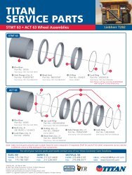
The BrakeRite II - Severe Duty utilizes the proven technology <strong>and</strong> performance of theBrakeRite EHB however, the installation process has been simplified in the new model.The features of the BrakeRite II - Severe Duty include:- Utilizes the st<strong>and</strong>ard proven EHB electronic control board, potted <strong>and</strong> enclosed in a remote mountedcontrol module- Provides complete Plug-In wiring harnesses to simplify field installation- In the event of field service, component replacement is simplified- Potted hybrid circuitry provides dependable service under adverse conditionsSD Control Module#2SDWiringHarness#3BrakeRite II#1#2BatteryCable#4Breakaway Switch#5BRAKERITE II SD KIT (includes everything listed above)Part Brake <strong>St<strong>and</strong>ard</strong> or PalletNo. Type Non-st<strong>and</strong>ard Weight Quantity4835700 Disc/Drum STD 13 TBDBRAKERITE II SD PARTS LISTRef # Part Number Part Description1 4834100 BrakeRite II2 4834200 SD Control Module3 4834300 SD Wiring Harness4 4834400 BrakeRite II Breakaway Battery Harness5 4834500 BrakeRite II Breakaway Battery SwitchCustom made harness’ are available upon request.Contact your sales representative for details.16
The BrakeRite II - RF applies the outst<strong>and</strong>ing BrakeRite EHB performance with radio frequencycontrol to provide quality braking for trailers to be towed by vehicles without the st<strong>and</strong>ard, hard wiredin-cab brake controllersThis system incorporates the latest in deceleration sensing by utilizing an accelerometer chip in thehybrid circuitry to apply the trailer brakes in proportion to the tow vehicle braking. The in-cabcontroller manual override is transmitted by RF (radio frequency) to the control module <strong>and</strong> is poweredby the in-cab power outlet (cigarette lighter).The features of the BrakeRite II - RF include:- Utilizes basic EHB electro-mechanical feature proven in field use- Has potted hybrid circuitry which functions even in severe environmental conditions- Plug-in technology provides for ease of installation <strong>and</strong>/or field serviceRF In-CabController #4BrakeRite II#1Breakaway Switch#6#2RF Control Module#2BRAKERITE II RF KIT (includes everything listed above)Part Brake <strong>St<strong>and</strong>ard</strong> or PalletNo. Type Non-st<strong>and</strong>ard Weight Quantity4835600 Disc/Drum STD 13 TBDCustom made harness’ are available upon request.Contact your sales representative for details.BatteryCable#5RF WiringHarness #3BRAKERITE II RF PARTS LISTRef # Part Number Part Description1 4834100 BrakeRite II2 4835100 RF Control Module3 4835500 RF Wiring Harness4 4835200 RF In-Cab Controller5 4834400 BrakeRite II Breakaway Battery Harness6 4834500 BrakeRite II Breakaway Battery Switch17
BRAKE RITE ACCESSORIES#1 #2 #3BRAKERITE EHB ACCESSORIESRef # Part Number Part Description1 4822100 Gel Cell Breakaway Kit with 2 Batteries2 4821800 Angle Mounting Bracket - unpainted3 4821900 Mounting Plate - unpainted!!! WARNING !!! Before using trailer always check:1) Brake fluid level must be maintained between three eighths & three quarters of an inch of fillercap opening.2) Prior to moving coupled units check unit to be certain system is functioning properly (consultowner’s manual).3) Prior to moving coupled units check BREAKAWAY PROTECTION. NEVER ATTEMPT TOMOVE/USE THE TRAILER if the Breakaway Battery is not fully charged.4) DO NOT RELY ON Towed Vehicle Brakes for entire unit braking. The Towed Vehicle Brake isonly to supplement the Braking System on the Towing Vehicle, NOT TO STOP THE ENTIRE UNIT.5) ALWAYS operate unit within prudent parameters <strong>and</strong> obey all laws.BrakeRite Limited Warranty:Eligibility: You are eligible for the benefits of this limited warranty if you are the original end-use purchaser of this BrakeRite EHB <strong>and</strong> if the unit has beenused only on the vehicle in which it was first installed.What Is Covered: <strong>Titan</strong> <strong>Tire</strong> warrants this product to be free from defects in material <strong>and</strong> workmanship for 18 months after the date of manufacture or oneyear from the date of retail sale, whichever occurs first, when properly installed , used <strong>and</strong> maintained.What Is Not Covered: The warranty does not apply to damage or loss caused by any of the following circumstances or conditions:1. Freight damage2. Misapplication, misuse, modification, or failure to follow the directions or observe cautions <strong>and</strong> warnings on installation, wiring, operation,application, inspection or maintenance specified in any <strong>Titan</strong> specification sheet, instruction <strong>and</strong> installation manual ;3. Using parts, accessories or components not specified in <strong>Titan</strong>’s specification sheet, instruction <strong>and</strong> installation manual or approved by <strong>Titan</strong>Distribution in writing.Conditions <strong>and</strong> Limitations: <strong>Titan</strong> <strong>Tire</strong>’s liability <strong>and</strong> purchaser’s remedy are expressly limited, at <strong>Titan</strong>’s sole option, to the repair or replacement of thedefective product. For the warranty to apply, <strong>Titan</strong> Distribution must receive notice of the alleged defect within 30 days of i) the alleged defect orii) the expiration of the warranty period, whichever is earlier. Any claim not made within this period shall conclusively be deemed void. <strong>Titan</strong>Distribution reserves the right to request that the product be returned to <strong>Titan</strong> Distribution, intact <strong>and</strong> postage prepaid, prior to processing a warrantyclaim.<strong>Titan</strong> Distribution shall not be liable for loss of use of the unit, or any other incidental or consequential costs, expenses or damagesincurred by the purchaser.Some states do not allow the exclusion or limitation of implied warranties, incidental or consequential damages, so the above limitations orexclusions may not apply to you. This warranty gives you specific legal rights. You may also have other rights which vary from state to state.To Receive Benefits Under This Warranty: Contact <strong>Titan</strong> <strong>Tire</strong> at the address or phone number below to obtain an authorization for return.<strong>Titan</strong> <strong>Tire</strong> CorporationAttention Warranty Dept.2345 E. Market StreetDes Moines, IA 50317800-832-8781The product must be returned, shipping costs prepaid, insured to the factory for evaluation.The following information should be available when contacting the factory <strong>and</strong> must accompany the return, legibly prepared: i) name, address <strong>and</strong>telephone number of purchaser, ii) proof of purchase including date, iii) model <strong>and</strong> serial number of the unit, iv) name <strong>and</strong> address of the dealerwhere the unit was purchased, v) description of the alleged defect.These terms <strong>and</strong> conditions represent the entire <strong>Titan</strong> Distribution BrakeRite EHB warranty, <strong>and</strong> no terms or conditions in any way adding to,modifying or otherwise altering the provisions stated herein shall bind <strong>Titan</strong> Distribution unless in writing signed by <strong>Titan</strong> Distribution.18
ULTRA-70ULTRA-70 SLIM LINE ACTUATORAll Ultra-70’s have a rated capacity of 7,000 G.V.W.R. 700 lbs. MAX. tongue load.The Ultra-70 is a streamlined actuator designed with an outer case to be attached <strong>and</strong> painted withyour trailer. The sleek inner cartridge is pleasing to the eye, but don’t let looks deceive you, theUltra-70 with it’s cast ball latch <strong>and</strong> high strength steel case is the most rugged actuator in its weightclass.Ultra-70- 7,000 lbs. capacity, 700 lb. tongue weight- Sleek, streamlined features to integrate with trailer design- Easily h<strong>and</strong>les twin 3,500 lb. axles- Can be used with disc or drum brakes (must specify type when ordering)- Outer case designed to be attached <strong>and</strong> painted with trailer- Bolt-on <strong>and</strong> weld-on versions available- Available in plated, primed or unpainted finishes- Equipped with an integral backup solenoid valveUltra-70 Assy. - Weld-on (un-painted)Part Brake <strong>St<strong>and</strong>ard</strong> or Master PalletNo. Type Non-st<strong>and</strong>ard Weight Cyl. Quantity4816000 Disc STD 22.5 4819200 304831000 Drum STD 22.5 4830900 30Ultra-70 Assy. - Bolt-on (plated)Part Brake <strong>St<strong>and</strong>ard</strong> or Master PalletNo. Type Non-st<strong>and</strong>ard Weight Cyl. Quantity4823200 Disc STD 22.5 4819200 304831100 Drum STD 22.5 4830900 30Ultra-70 Assy. Bolt-on (primed)Part Brake <strong>St<strong>and</strong>ard</strong> or Master PalletNo. Type Non-st<strong>and</strong>ard Weight Cyl. Quantity4823300 Disc STD 22.5 4819200 304831200 Drum STD 22.5 4830900 3019
ULTRA-70 Parts ListItem Number Quantity Part Number Description1 1 4816200 Inner assembly2 2 4811300 Pin3 1 4819100 Damper4 4 4818500 Roller5 4 4818700 Sleeve, roller6 1 4819600 Outer case, weld-on uncoated version1 4823400183 Outer case, bolt-on plated version1 4823400317 Outer case, bolt-on painted version7 1 4818400 Damper pin8 3 4511100 Retaining ring 1/2" dia.9 1 4818300 Ball latch pivot pin10 2 4850700 Retaining ring 5/8" dia.11 1 4820200 Ball latch spring12 1 4818200 Ball latch13 1 4818600 Break away lock lever14 1 4818800 Break away lock spring16 4832100 Complete inner assembly, disc brake4832200 Complete inner assembly, drum brake17 1 4819200 Master cylinder, disc brake1 4830900 Master cylinder, drum brake18 1 4830600 Filler cap, master cylinder, diaphram1 4813700 Filler cap, master cylinder, vented19 1 4819400 Safety lock pin with lanyard20 1 4819300 Back-up valve21 1 4822300 Breakaway cable22 1 4750300 Orifice connector, disc brake1 1209800 Orifice connector, drum brakePushrod Assy. 1 4818900 Push rod15 1 4822200 Cable bracket1 2338600 Spring1 2338500 Washer20
Model 6 Actuator with 2 5 /16” Ball Coupler7,500 pound capacity, Max. G.V.W.R., 600 pound tongue load, G.V.W.R. limited toball rating.Part No. Part No. Brake <strong>St<strong>and</strong>ard</strong> Pallet Master Master CPLRPrimed Plated Type or Non- Weight Qty. Cyl. Cyl. Assy. Repair Description<strong>St<strong>and</strong>ard</strong>Kit4079200 Drum STD 35 22 10271 1777401 1848700 2 5 /16 CPLR Bolt-On4747200 Disc STD 35 22 47470 1777405 1848700 2 5 /16 CPLR Bolt-On4079200317 Drum *NON-STD 35 22 10271 1777401 1848700 2 5 /16 CPLR Bolt-On4747200317 Disc *NON-STD 35 22 47470 1777405 1848700 2 5 /16 CPLR Bolt-OnNOTE: For 3” wide trailer tongue.*Non-<strong>St<strong>and</strong>ard</strong> Actuators require minimum 8-week lead time <strong>and</strong> minimum order quantity may be required.Model 6 A-Frame (50º) Actuator w/Lunette Eye7,500 pound capacity, Max. G.V.W.R., 600 pound tongue load.Part No. Part No. Brake <strong>St<strong>and</strong>ard</strong> Pallet Master Master CPLRPrimed Plated Type or Non- Weight Qty. Cyl. Cyl. Assy. Repair Description<strong>St<strong>and</strong>ard</strong>Kit4045500 Drum *NON-STD 41 14 10271 1777401 L-Eye Weld-OnNOTE: Disc Brake version is available upon request.*Non-<strong>St<strong>and</strong>ard</strong> Actuators require minimum 8-week lead time <strong>and</strong> minimum order quantity may be required.Model 6 A-Frame (50º) Actuator with 2 5 /16”Ball Coupler7,500 pound capacity, Max. G.V.W.R., 600 pound tongue loadG.V.W.R. limited to ball ratingPart No. Part No. Brake <strong>St<strong>and</strong>ard</strong> Pallet Master Master CPLRPrimed Plated Type or Non- Weight Qty. Cyl. Cyl. Assy. Repair Description<strong>St<strong>and</strong>ard</strong>Kit4067600 Drum *NON-STD 38 14 10271 1777401 2 5 /16 CPLR Weld-OnNOTE: Disc Brake version is available upon request.*Non-<strong>St<strong>and</strong>ard</strong> Actuators require minimum 8-week lead time <strong>and</strong> minimum order quantity may be required.Model 6 Straight Actuator with Lunette Eye7,500 pound capacity, Max. G.V.W.R., 600 pound tongue loadPart No. Part No. Brake <strong>St<strong>and</strong>ard</strong> Pallet Master Master CPLRPrimed Plated Type or Non- Weight Qty. Cyl. Cyl. Assy. Repair Description<strong>St<strong>and</strong>ard</strong>Kit4093200 Drum *NON-STD 38 20 10271 1777401 L-Eye Bolt-On4748000 Disc *NON-STD 38 20 47470 1777405 L-Eye Bolt-OnNOTE: For 3” wide trailer tongue.NOTE: Padlock (Master Lock #30) works with a 2 5 /16” Ball Coupler.*Non-<strong>St<strong>and</strong>ard</strong> Actuators require minimum 8-week lead time <strong>and</strong> minimum order quantity may be required.21
Model 6 Actuator with Multi-fit Ball Coupler6,000 pound capacity, Max. G.V.W.R., 600 pound tongue loadG.V.W.R. limited to ball rating.Part No. Part No. Brake <strong>St<strong>and</strong>ard</strong> Pallet Master Master CPLRPrimed Plated Type or Non- Weight Qty. Cyl. Cyl. Assy. Repair Description<strong>St<strong>and</strong>ard</strong>Kit2480000 Drum STD 28 22 10271 1777401 40454 CPLR Bolt-On4747900 Disc STD 28 22 47470 1777405 40454 CPLR Bolt-OnNOTE: Fits 1 5 /16”, 50mm <strong>and</strong> 2” ball.For 3” wide trailer tongue.Model 6 A-Frame (50º) Actuator with Multi-fitBall Coupler6,000 pound capacity, Max. G.V.W.R., 600 pound tongue loadG.V.W.R. limited to ball rating.Part No. Part No. Brake <strong>St<strong>and</strong>ard</strong> Pallet Master Master CPLRPrimed Plated Type or Non- Weight Qty. Cyl. Cyl. Assy. Repair Description<strong>St<strong>and</strong>ard</strong>Kit2492800 Drum STD 31 14 10271 1777401 40454 CPLR Bolt-OnNOTE: Fits 1 5 /16”, 50mm <strong>and</strong> 2” ball.NOTE: Disc Brake version is available upon request.Model 6 Actuator with Leveler Channel7,500 pound capacity, Max. G.V.W.R., 600 pound tongue loadG.V.W.R. limited to ball rating.Part No. Part No. Brake <strong>St<strong>and</strong>ard</strong> Pallet Master Master CPLRPrimed Plated Type or Non- Weight Qty. Cyl. Cyl. Assy. Repair Description<strong>St<strong>and</strong>ard</strong>Kit4744901 Drum *NON-STD 28 10271 1777401 40454 CPLR Bolt-OnNOTE: Disc Brake version is available upon request.*Non-<strong>St<strong>and</strong>ard</strong> Actuators require minimum 8-week lead time <strong>and</strong> minimum order quantity may be required.22
MODEL 6 ACTUATOR PARTS DIAGRAM#2403423
MODEL 6 ACTUATOR PARTS LIST(REFER TO DIAGRAM ON PAGE 23)Key No. Part No. Description Qty Reqd.1 2480100183 Outer Case Assy 11A 2493000 Outer Case Assy 12 1242700 Bearing 23 1776300 Front Roller 14 1776600 Front Roller Pin 15 0799700 Cotter Pin 1/8 x 3/4 26 1776700 Front Roller Cover #6000 16 4350700183 Front Roller Cover #7500 17 4594100 Breakaway Lever w/Pin 18 1055500 S-Hook - Part of 4594100 19 1780300 Breakaway Spring 110 1781500 Hex Bolt 5/16 x 1/2 Self Tapping 411 1861900 Washer 1x 12 1776200 Cylinder Mounting Plate 1x 13 1027300 Hex Bolt 3/8 NC x 5 2x 14 4390500 Push Rod Assy 115 * 2496400 Lock-Ring 1x 16 1027100 Master Cylinder - Drum Brake 1x 16 4747000 Master Cylinder - Disc Brake 1x 17 1755600 Master Cylinder Cap w/gasket 118 1209800 Connector - 1/64 Orifice - Drum Brake 14750300 Connector - Disc Brake 1x 19 0797600 Nut - Hex 3/8 NC 2x 20 0782000 Washer 3/8 2x 21 1027400 Spring 222 1242600 Damper 123 0829100 Rear Roller 224 1777300 Master Pin 125 0815200 Cotter Pin 126 1777200 Damper Pin 127 4391600 Inner Slide Assy w/ Bolt, Locknut, <strong>and</strong> Ball Latch 128 1831600 Washer 129 1806600183 Cover 130 * 2338100 Latch Bolt 131 * 1809000 Lock Plate 132 * 4335800 Ball Latch 133 * 4336800 Compression Spring 134 * 2338300 H<strong>and</strong> <strong>Wheel</strong> Lock 135 * 2420000 H<strong>and</strong> <strong>Wheel</strong> 136 * 2339000 Bolt - Hex 7/16 NF 2-5/8 137 * 2339100 Locknut - Hex 7/16 NF Thin 138 4045600 Inner Slide w/3" Lunette Eye 139 4067700183 Inner Slide w/2-5/16" Ball Coupler 11502600 Master Cylinder Repair Kit Wagner 14045400 Multi-Fit Coupler Repair Kit (bolt & locknut, replace riveted pin) 11848700 2-5/16" Ball Coupler Repair Kit 14808000 Backup Valve Kit 1x These parts are included in the master cylinder assembly # 1777401 & 1777405* These parts are included in the 4045400 Coupler Repair Kit24
Model 60 Leverlock Actuator6,000 pound capacity, Max. G.V.W.R., 600 pound tongue loadG.V.W.R. limited to ball rating.Part No. Part No. Brake <strong>St<strong>and</strong>ard</strong> Pallet Master Master CPLRPrimed Non- Plated Type or Non- Weight Qty. Cyl. Cyl. Assy. Repair Description<strong>St<strong>and</strong>ard</strong> <strong>St<strong>and</strong>ard</strong> Kits Kit4338600 4332900 Drum STD 20 36 23361 43951 43584 3” Tongue4819900 4715400 Disc STD 20 36 47142 4820000 43584 3” TongueNOTE: For 3” wide trailer tongue.NOTE: Fits 1 7 /8”, 50mm <strong>and</strong> 2” Ball. (some adjustment required)NOTE: PRIMED PARTS ARE NON-STANDARDModel 60 Leverlock Actuator w/ Solenoid Cover6,000 pound capacity, Max. G.V.W.R., 600 pound tongue loadG.V.W.R. limited to ball rating.Part No. Part No. Brake <strong>St<strong>and</strong>ard</strong> Pallet Master Master CPLRPrimed Non- Plated Type or Non- Weight Qty. Cyl. Cyl. Assy. Repair Description<strong>St<strong>and</strong>ard</strong> <strong>St<strong>and</strong>ard</strong> Kits Kit4338610 4332910 Drum STD 20 30 23361 43951 43584 3” Tongue4819910 4715410 Disc STD 20 30 47142 4820000 43584 3” TongueNOTE: For 3” wide trailer tongue.NOTE: Fits 1 7 /8”, 50mm <strong>and</strong> 2” Ball. (some adjustment required)NOTE: PRIMED PARTS ARE NON-STANDARDModel 60 Multi-fit Actuator6,000 pound capacity, Max. G.V.W.R., 600 pound tongue loadG.V.W.R. limited to ball rating.Part No. Part No. Brake <strong>St<strong>and</strong>ard</strong> Pallet Master Master CPLRPrimed Non- Plated Type or Non- Weight Qty. Cyl. Cyl. Assy. Repair Description<strong>St<strong>and</strong>ard</strong> <strong>St<strong>and</strong>ard</strong> Kits Kit4339900 4339700 Drum STD 20 36 23361 43951 40454 3” Tongue4815200 4745700 Disc STD 20 36 47142 4820000 40454 3” TongueNOTE: For 3” wide trailer tongue.NOTE: Fits 1 7 /8”, 50mm <strong>and</strong> 2” Ball.NOTE: PRIMED PARTS ARE NON-STANDARDModel 60 Multi-fit Actuator w/ Solenoid Cover6,000 pound capacity, Max. G.V.W.R., 600 pound tongue loadG.V.W.R. limited to ball rating.RE-RATED!Part No. Part No. Brake <strong>St<strong>and</strong>ard</strong> Pallet Master Master CPLRPrimed Non- Plated Type or Non- Weight Qty. Cyl. Cyl. Assy. Repair Description<strong>St<strong>and</strong>ard</strong> <strong>St<strong>and</strong>ard</strong> Kits Kit4339910 4339710 Drum STD 20 30 23361 43951 40454 3” Tongue4815210 4745710 Disc STD 20 30 47142 4820000 40454 3” TongueNOTE: For 3” wide trailer tongue.NOTE: Fits 1 7 /8”, 50mm <strong>and</strong> 2” Ball.NOTE: PRIMED PARTS ARE NON-STANDARDAero 7500 Actuator with Lockout Lever7,500 pound capacity, Max. G.V.W.R., 750 pound tongue load.Part No. Part No. Brake <strong>St<strong>and</strong>ard</strong> Pallet Master Master CPLRPrimed Plated Type or Non- Weight Qty. Cyl. Cyl. Assy. Repair Description<strong>St<strong>and</strong>ard</strong> Kits Kit4500600 Drum STD 24 36 23361 43951 3” Tongue4606500 Disc STD 24 36 47142 4820000 3” Tonguelockout leverNOTE: Use only with 2” diameter tow ball.G.V.W.R. limited to that of the ball & hitch being used.25
LEVER-LOCKMODEL 60 ACTUATOR DIAGRAM25635351143031101313873189141318220211915INCLUDED IN 153631221630313717#4098932263324926
MULTI-FITMODEL 60 ACTUATOR DIAGRAM29282726252423634351143031101313873189141318220211915INCLUDED IN 15363122163031371727
MODEL 60 ACTUATOR PARTS LIST(REFER TO DIAGRAMS ON PAGE 26 & 27)Ref No. Part No. DescriptionMulti-FitMarine43397, 47457Multi-FitPainted43399, 48152Lever-LockMarine43329, 47154Lever-LockPainted43386, 481991 4324600 Outer Case 1 11 4338700 Outer Case 1 12 2337700 Strut 1 1 1 13 2337800 Coupler Case 13 4097000 Coupler Case 13 4332500 Coupler Case 13 4338800 Coupler Case 14 2336200 Damper 1 1 1 15 2339000 Bolt, Hex 7/16 NF x 2-5/8 1 1 1 16 2339100 Locknut, Hex 7/16 NF Thin 1 1 1 17 2327800 Roller 4 4 4 48 2341300 Bolt, Hex 1/2 NF x 3-3/4 2 2 2 29 1861200 Locknut, Hex 1/2 NF 2 2 3 310 4623800 Breakaway Assy. w/pin, cover, s-hook 1 1 1 111 1055500 S-hook - included with 46238 1 1 1 113 4005200 Breakaway Spring 1 1 1 114 2346300 Push Rod Assembly 1 1 1 115 * 2336100042 Master Cylinder - Drum Brake 1 1 1 115 * 4714200042 Master Cylinder - Disc Brake 1 1 1 116 * 2341400 Gasket 1 1 1 117 * 1209800 Connecor, 1/64" orifice - Drum Brake 1 1 1 117 * 4750300 Connector - Disc Brake 1 1 1 118 * 1050800 Bolt, Hex 1/4 NC x 3/4 4 4 4 419 * 0794000 Lockwasher 1/4 4 4 4 420 * 4480701 Filler ap, 1-1/4-18 NEF plastic 1 1 1 121 * 2338900 Gasket, Filler Cap 1 1 1 122 * 2356600 Cover, Master Cylinder 1 1 1 123 2338100 Latch Bolt 1 124 1809000 Lock Plate 1 1 1 125 4335800 Ball Latch 1 1 1 126 4336800 Spring 1 1 1 127 2338300 H<strong>and</strong> <strong>Wheel</strong> Lock 1 128 2420000 H<strong>and</strong> <strong>Wheel</strong> 1 129 2496400 Lock Ring 1 130 2452500183 Cover, Front 2 230 2452500317 Cover, Front 2 231 1094100 Screw, Cover 6 6 6 632 4358500 H<strong>and</strong>le Assembly 1 133 4334500 Spring Plate 1 134 4045400 Multi-Fit Coupler Repair Kit 1 135 4358400 Lever-Lock Coupler Repair Kit 1 136 1502600 Master Cylinder Repair Kit Wagner 1 1 1 137 4395100 Master Cylinder Kit (includes * parts) Drum Brakes 1 1 1 137 4820000 Master Cylinder Kit (includes * parts) Disc Brakes 1 1 1 138 4835800183 Solenoid Valve Cover, plated 1 138 4835800 Solenoid Valve Cover, painted 1 14748800 Solenoid ValveRECOMMENDED TOOLSSocket <strong>and</strong> wrench setsNut DriversTorque wrenchSnap ring pliersFlat-blade screw driver28
AERO 7500 ACTUATOR ASSEMBLY DIAGRAM29
AERO 7500 ACTUATOR PARTS LIST(REFER TO DIAGRAMS ON PAGE 29)Ref No. Part No. DescriptionDrum Brake4500600Disc Brake46065002 4500700 Outer Case, plated 1 13 4518100183 Coupler Case Assembly, plated 1 14 4502000 Damper 1 15 4511400 1/2" Damper Pin/Ball Latch Pin 2 26A 2336100042 Master Cylinder, drum brake 16B 4714200042 Master Cylinder, disc brake 17 4518200 Cover, Master Cylinder 1 18 4524400 Gasket, Master Cylinder 1 19A 1209800 Orifice Connector, .015" diameter 19B 4750300 Connector, .125" diameter 110 4480701 Filler Cap with gasket 1 111 4624200 Bolt, 1/4 - 20 X .875 4 412 794000 Lockwasher, 1/4" st<strong>and</strong>ard 4 413 4502700 Push Rod & Breakaway Cable Assy. 1 114 2338400 Push Rod 1 115 2338500 Washer, push rod 1 116 2338600 Spring, overload 1 117 1740600 Lock Nut, 5/16" - 18 NC 2 218 4518300 Spring Guide 1 119 4501300 Breakaway Cable 1 120 1055500 S - Hook 1 121 4597100 Breakaway Lever 1 122 4599500 Roll Pin, 3/16 X 1/2 1 123 4518400 Rear roller, sintered iron 2 2-24 4518500 Front Roller 1 125 2341300 Bolt, 1/2" NF x 3 3/4 Hex head 3 326 4835400 1/2" NF locknut, half height 3 328 4809000 Elbow, 90 degree, 1/8 NPT, optional 1 129 4524900 Roller Separator 1 131 4501100 H<strong>and</strong>le 1 132 4500900 Ball Latch, cast 1 133 4520000 Spring, ball latch 1 134 4811500 Bolt, 5/16 - 18 NC X 3 1 135 4518600 Groove Pin, 1/4" 1 136 4518700 Retaining Ring, 1/4" 1 137 4521500 Spring, h<strong>and</strong>le 1 138 4501400 Spring, breakaway catch 1 139 4597200 Pin, breakaway catch 1 140 4600100183 Lockout Lever 1 141 4600000 Lockout Spring 1 142 4745500 Label, disc brake actuator 143 4706400 Quick Release Pin & Lanyard 1 144 1502600 Master Cylinder Repair Kit NA45 4748800 Backup ValveRecommended Tools:7/16” wrenchSnap Ring PliersTorque wrenchLocking pliers30
Basic capacity 10,000 lbs. G.V.W.R., 800 lbs. tongue loadThe Model 10 is demountable when installed with mountingchannel for 3” width tongue or may be welded for permanentinstallation. This actuator is available with ball couplers, 3” lunetteeye, <strong>and</strong> adjustable clevis hitch. Usage suggested forrecreational <strong>and</strong> light industrial trailers towed by passenger cars<strong>and</strong> light trucks. ZINC PLATED (MARINE) MODELS AVAILABLEFOR GREATER CORROSION RESISTANCE.1Model 10 Actuator with Leveler Channel10,000 pound capacity4321234Part No. Part No. Brake <strong>St<strong>and</strong>ard</strong> Pallet Master Master CPLRPrimed Plated Type or Non- Weight Qty. Cyl. Cyl. Assy. Repair Description<strong>St<strong>and</strong>ard</strong>Kit2404600 Drum STD 45 15 23744 2374600 Leveler Channel Only1607900 Drum STD 54 15 23744 2374600 8979 Clevis Hitch1890900 Drum STD 57 15 23744 2374600 18487 18820 2 5 /16 CPLR1891100 Drum STD 57 15 23744 2374600 16137 Lunette EyeDisc Brake version available upon request3Model 10 Actuator with Leveler Channel <strong>and</strong>Mounting Channel For 3” Width Tongue10,000 pound capacity2112332Part No. Part No. Brake <strong>St<strong>and</strong>ard</strong> Pallet Master Master CPLRPrimed Plated Type or Non- Weight Qty. Cyl. Cyl. Assy. Repair Description<strong>St<strong>and</strong>ard</strong>Kit4238300 Drum *NON-STD 60 15 23744 2374600 18487 2 5 /16 CPLR4238500 4809800 Drum *NON-STD 61 15 23744 2374600 With Lunette Eye2324800 4809700 Drum *NON-STD 49 15 23744 2374600 Leveler4809900 Disc *NON-STD 49 15 47471 4749501042 Act w/Leveler4810000 Disc *NON-STD 61 15 47471 4749501042 With Lunette Eye*Non-<strong>St<strong>and</strong>ard</strong> actuators require minimum 8-week lead time <strong>and</strong> minimum quantity may be requiredModel 10 Actuator with 2 5 /16” Drop CouplerLess Channel10,000 pound capacityPart No. Part No. Brake <strong>St<strong>and</strong>ard</strong> Pallet Master Master CPLRPrimed Plated Type or Non- Weight Qty. Cyl. Cyl. Assy. Repair Description<strong>St<strong>and</strong>ard</strong>Kit1735200 Drum STD 53 15 23744 2374600 18487 2 5 /16 CPLR Weld-OnDisc Brake version available upon request31
10,000 pound capacityModel 10 Actuator - Straight2 5 /16” Ball Coupler Less ChannelPart No. Part No. Brake <strong>St<strong>and</strong>ard</strong> Pallet Master Master CPLRPrimed Plated Type or Non- Weight Qty. Cyl. Cyl. Assy. Repair Description<strong>St<strong>and</strong>ard</strong>Kit1607500 Drum STD 50 18 23744 2374600 18487 2 5 /16 CPLR Weld-On4749600 Disc STD 50 18 47471 4749501042 2 5 /16 CPLR Weld-OnModel 10 Actuator - Straight with Lunette EyeLess Channel10,000 pound capacityPart No. Part No. Brake <strong>St<strong>and</strong>ard</strong> Pallet Master Master CPLRPrimed Plated Type or Non- Weight Qty. Cyl. Cyl. Assy. Repair Description<strong>St<strong>and</strong>ard</strong>Kit1607700 Drum **NON-STD 54 18 23744 2374600 L-Eye Weld-On*1664500 Drum **NON-STD 58 15 23744 2374600 L-Eye Bolt-On*With mounting channel for 3” width tongue.**Non-<strong>St<strong>and</strong>ard</strong> actuators require minimum 8-week lead time <strong>and</strong> minimum quantity may be requiredDisc Brake version available upon requestModel 10 Actuator less Coupler <strong>and</strong> Channel10,000 pound capacityPart No. Part No. Brake <strong>St<strong>and</strong>ard</strong> Pallet Master Master CPLRPrimed Plated Type or Non- Weight Qty. Cyl. Cyl. Assy. Repair Description<strong>St<strong>and</strong>ard</strong>Kit1608000 Drum STD 41 30 23744 2374600 Weld-OnDisc Brake version available upon requestModel 10 Actuator - Straight less Coupler,with Mounting Channel for 3” Width Tongue10,000 pound capacityPart No. Part No. Brake <strong>St<strong>and</strong>ard</strong> Pallet Master Master CPLRPrimed Plated Type or Non- Weight Qty. Cyl. Cyl. Assy. Repair Description<strong>St<strong>and</strong>ard</strong>Kit1664900 Drum *NON-STD 45 15 23744 2374600 Bolt-On*Non-<strong>St<strong>and</strong>ard</strong> actuators require minimum 8-week lead time <strong>and</strong> minimum quantity may be required32
Model 10 Actuator - Straight with 2 5 /16” Ball Coupler<strong>and</strong> Mounting Channel for 3” Width Tongue10,000 pound capacityPart No. Part No. Brake <strong>St<strong>and</strong>ard</strong> Pallet Master Master CPLRPrimed Plated Type or Non- Weight Qty. Cyl. Cyl. Assy. Repair Description<strong>St<strong>and</strong>ard</strong>Kit2477600 Drum STD 54 15 23744 2374600 18487 2 5 /16 CPLR Bolt-On1664300 Drum *NON-STD 54 15 23744 2374600 18487 2 5 /16 CPLR Bolt-On4750800 Disc STD 54 15 47471 4749501042 18487 2 5 /16 CPLR Bolt-On*Non-<strong>St<strong>and</strong>ard</strong> Actuators require minimum 8-week lead time <strong>and</strong> minimum order quantitymay be required.Model 10 Actuator - 2 5 /16” Ball Drop Coupler<strong>and</strong> Mounting Channel for 3” Width Tongue10,000 pound capacityPart No. Part No. Brake <strong>St<strong>and</strong>ard</strong> Pallet Master Master CPLRPrimed Plated Type or Non- Weight Qty. Cyl. Cyl. Assy. Repair Description<strong>St<strong>and</strong>ard</strong>Kit2478100 Drum STD 57 15 23744 2374600 18487 2 5 /16 CPLR Bolt-On4750600 Disc STD 57 15 47471 4749501042 18487 2 5 /16 CPLR Bolt-On1772700 Drum STD 56 15 23744 2374600 18487 2 5 /16 CPLR Bolt-On*Use 5 /8” Mounting Bolt.NOTE: Padlock (Master Lock #30) works with a 2 5 /16” Ball Coupler.Model 10 Actuator Product ListPart # Drum Part # Disc Description Attachment Inner Outer1608000 No coupler, painted Weld-on 1593300 16016002404600 W/leveler channel, painted Weld-on 1608700317 16016004809700 4809900 W/leveler channel, plated Bolt-on 5/8" 4721700 24782004721600 W/leveler channel, plated Bolt-on 1/2" 4721700 24777001831607500 4749600 2 5/16" coupler, straight, painted Weld-on 1608400317 16016001664300 2 5/16" coupler, 2.5" offset, painted Bolt-on 1/2" 1648400317 24777003172477600 4750800 2 5/16" coupler, 2.5" offset, plated Bolt-on 1/2" 1608400183 24777001831735200 4830300 2 5/16" drop coupler, painted Weld-on 2478300317 16016001772700 4830100 2 5/16" drop, 1" offset mtg channel Bolt-on 5/8" 2478300317 16855002478100 4750600 2 5/16" drop coupler, plated Bolt-on 5/8" 2478300183 24782001890900 2 5/16" adj. coupler, painted Weld-on 1608700317 16016004238300 2 5/16" adj. coupler, 1" ofset channel Bolt-on 5/8" 1608700317 16855001891100 3" adjustable lunette eye, painted Weld-on 1608700317 16016001607900 Adjustable clevis hitch, painted Weld-on 1608700317 16016001607700 3" lunette eye, painted Weld-on 1608600 16016001664900 No coupler, 2.5" offset mtg. channel Bolt-on 1/2" 1593300 24777003171664500 3" lunette eye, 2.5" offset mtg. channel Bolt-on 1/2" 1608600 24777003174238500 W/leveler channel, 1" ofset mtg. channel Bolt-on 5/8" 1608700317 16855004299600 2 5/16" drop, 2.5" offset mtg. channel Bolt-on 1/2" 2478300183 24777001832324800 W/leveler channel, 2.5" mtg. channel Bolt-on 1/2" 1608700317 247770031733
MODEL 10 ACTUATOR PARTS LIST34
MODEL 10 ACTUATOR PARTS LIST(REFER TO DIAGRAM ON PAGE 34)Ref No. Part No. Description Qty Reqd.1 1601600 Outer case, painted 147 2478200 Outer case, 1" offset mtg channel, plated 147 1685500 Outer case, 1" offset mtg channel, painted 148 2477700183 Outer case, 2.5" offset mtg channel, plated 148 2477700317 Outer case, 2.5" offset mtg channel, painted 12 1020900 Bearing (top <strong>and</strong> bottom), 0.125" thick 63 1242700 Bearing (side), 0.075" thick 84 1601900 Front roller 15 828800 Front roller bolt 16 799700 Cotter pin 1/8 x 1 27 1601800 Front roller cover 18 776800 Breakaway chain 19 1055500 S-hook 210 1054100 Breakaway lever assembly 111 1055200 Weather seal 112 1052600 Breakaway lock -left 113 1052700 Breakaway lock - right 114 793800 Lock washer 5/16" std 815 794900 Bolt - hex 5/16" - 18NC x 5/8" 416 1507000 Cylinder cover 117 794800 Bolt - hex 5/16" - 18NC x 1/2" 418 1593300 Inner slide 119 2374400 Master cylinder 1 1/4" bore - drum brake 14831600 Master cylinder, drum, with 1209800 orifice 14747100 Master cylinder 1 1/4" bore - disc brake 120 838800 Cylinder bracket right h<strong>and</strong> 121 1250300 Filler cap (included in 2374400) 122 774500 Gasket - for use with 1209900 orifice w/ 1/2" NF 123 1209800 Orifice connector, drum brake, 1/8 NPT 14750300 Orifice connector, disc brake, 1/8" NPT 11209900 Orifice, drum, early type, 1/2" NF thread 124 838900 Cylinder bracket, left h<strong>and</strong> 125 827100 Bolt - hex 3/8" - 16NC x 3" 226 797600 Hex nut 3/8 - 16NC 227 1255200 Star lock washer 3/8" 228 830100 Push rod block 129 1242600 Damper 230 829100 Rear roller 231 1593500 Master pin 232 815200 Cotter pin 3/16" x 1 1/4" 233 1593400 Damper pin 240 793700 Lock washer 1/2" 141 798500 Hex nut 1/2" - 13NC 142 144901 Grease zerk 148 1861900 Nylon washer 22374600 Drum brake master cylinder assy 1complete with brackets2374601 Drum brake master cylinder assy 1complete with brackets, painted black4749500 Disc brake master cylinder assy 1complete with brackets4749501042 Disc brake master cylinder assy 1complete with brackets - painted black4750400 Back up valve kit - 1/2" NF master cylinders 14748800 Back up valve kit - 1/8" NPT master cylinders 135
Model 20 Actuator - less Coupler20,000 pound capacity, G.V.W.R., 2,000 pound tongue loadPart No. Part No. Brake <strong>St<strong>and</strong>ard</strong> Pallet Master Master CPLRPrimed Plated Type or Non- Weight Qty. Cyl. Cyl. Assy. Repair Description<strong>St<strong>and</strong>ard</strong>Kit1055100 Drum STD 65 18 23744 2374600 Weld-On4749700 Disc STD 65 18 47471 4749501042 Weld-OnModel 20 Actuator Straight with Lunette Eye20,000 pound capacity, G.V.W.R., 2,000 pound tongue loadPart No. Part No. Brake <strong>St<strong>and</strong>ard</strong> Pallet Master Master CPLRPrimed Plated Type or Non- Weight Qty. Cyl. Cyl. Assy. Repair Description<strong>St<strong>and</strong>ard</strong>Kit1297400 Drum STD 79 15 23744 2374600 L-Eye Weld-OnDisc Brake version available upon requestModel 20 Actuator Straight with 2 5 /16” Ball Coupler20,000 pound capacity, G.V.W.R., 2,000 pound tongue loadPart No. Part No. Brake <strong>St<strong>and</strong>ard</strong> Pallet Master Master CPLRPrimed Plated Type or Non- Weight Qty. Cyl. Cyl. Assy. Repair Description<strong>St<strong>and</strong>ard</strong>Kit1521000 Drum STD 74 15 23744 2374600 18487 2 5 /16 CPLR Weld-On4750500 Disc STD 74 15 47471 4749501042 18487 2 5 /16 CPLR Weld-OnModel 20 Actuator - 2 5 /16” Drop Coupler20,000 pound capacity, G.V.W.R., 1,200 pound tongue loadPart No. Part No. Brake <strong>St<strong>and</strong>ard</strong> Pallet Master Master CPLRPrimed Plated Type or Non- Weight Qty. Cyl. Cyl. Assy. Repair Description<strong>St<strong>and</strong>ard</strong>Kit1735100 Drum *NON-STD 76 12 23744 2374600 18487 2 5 /16 CPLR Weld-On4830400 Disc *NON-STD 76 12 47471 4749501042 18487 2 5 /16 CPLR Weld-On36
Model 20 Actuator with Leveler Channel12,000 pound capacity, G.V.W.R., 1,200 pound tongue load134422Part No. Part No. Brake <strong>St<strong>and</strong>ard</strong> Pallet Master Master CPLRPrimed Plated Type or Non- Weight Qty. Cyl. Cyl. Assy. Repair Description<strong>St<strong>and</strong>ard</strong>Kit1889800 Drum STD 82 15 23744 2374600 18487 w/18820 2 5 /16 CPLR4750000 Disc STD 82 15 47471 4749501042 18487 w/18820 2 5 /16 CPLR1777800 Drum STD 82 15 23744 2374600 w/16137 Lunette Eye4750100 Disc STD 82 15 47471 4749501042 w/16137 Lunette Eye2420,000 pound capacity, G.V.W.R., 2,000 pound tongue loadPart No. Part No. Brake <strong>St<strong>and</strong>ard</strong> Pallet Master Master CPLRPrimed Plated Type or Non- Weight Qty. Cyl. Cyl. Assy. Repair Description<strong>St<strong>and</strong>ard</strong>Kit1 1899100 Drum STD 70 15 23744 2374600 Basic ACT Only1 4749800 Disc STD 70 15 47471 4749501042 Basic ACT Only3 1811700 Drum STD 81 15 23744 2374600 w/18078 Clevis Hitch3 4749900 Disc STD 81 15 47471 4749501042 w/18078 Clevis HitchModel 20 Actuator - 2 5 /16” Drop Coupler withMounting Channel20,000 pound capacity, GVWR., 2,000 pound tongue loadPart No. Part No. Brake <strong>St<strong>and</strong>ard</strong> Pallet Master Master CPLRPrimed Plated Type or Non- Weight Qty. Cyl. Cyl. Assy. Repair Description<strong>St<strong>and</strong>ard</strong>Kit4042700 Drum STD 80 12 23744 2374600 18487 2 5 /16 CPLR Bolt-On4750700 Disc STD 80 12 47471 4749501042 18487 2 5 /16 CPLR Bolt-OnModel 20 Actuator - 2 5 /16” Straight withMounting Channel20,000 pound capacity, GVWR., 2,000 pound tongue loadPart No. Part No. Brake <strong>St<strong>and</strong>ard</strong> Pallet Master Master CPLRPrimed Plated Type or Non- Weight Qty. Cyl. Cyl. Assy. Repair Description<strong>St<strong>and</strong>ard</strong>Kit4053400 Drum *NON-STD 78 12 23744 2374600 18487 2 5 /16 CPLR Bolt-OnNOTE: Padlock (Master Lock #30) works with a 2 5 /16” Ball Coupler.Disc Brake version available upon request*Non-<strong>St<strong>and</strong>ard</strong> Actuators require minimum 8-week lead time <strong>and</strong> minimum orderquantity may be required.37
MODEL 20 ACTUATOR PARTS DIAGRAM38
(REFER TO DIAGRAM ON PAGE 38)MODEL 20 ACTUATOR PARTS LISTKey # Part Number Description1 1055300317 Outer Case - Primer1734900 Outer Case w/Mounting Channel - Primer4488300 Outer Case w/Mounting Channel - Plated2 1556300317 Inner Slide - No Coupler, Primer4490400317 Inner Slide w/2 5/16 Drop Coupler4490400183 Inner Slide w/2 5/16 Drop Coupler - Plated3 0828400 Centering Rail4 1601900 Front Roller - Plated5 0828800 Front Roller Bolt 5/8"x 5 1/4" - 1/2 NC6 0798500 Hex Nut 1/2" NC7 0793700 Lockwasher 1/2"8 0144901 Grease Zerk9 0828900317 Front Roller Cover - Primer0828900183 Front Roller Cover - Painted10 0829100 Rear Roller11 0829400 Rear Roller Bolt - 5/8"x 5" NF, Grade 512 0797100 Slotted Hex Nut - 5/8" NF13 0332800 Spacer14 1250300 Filler Cap (included in 2374400)14 2374400 Master Cylinder, Disc Brake, 1 1/4" bore4831600 Master Cylinder, Drum, with 12098004747100 Master Cylinder, Disc Brake, 1 1/4" bore15 0829700 Spacer16 0799400 Cotter Pin, 1/8"x1 1/4"17 0778400 Damper18 0829800 Damper Pin19 0830100 Pushrod Block20 0799700 Cotter Pin, 1/8"x 3/4"21 0798400 Bolt 5/16"x 1/2" NC, Grade 522 1248900 Star Lockwasher, 5/16"23 1507000 Cylinder Cover24 0827100 Bolt 3/8"x 3" NC, Grade 525 1255200 Star Lockwasher, 3/8"26 0797600 Hex Nut 3/8" NC27 0794900 Bolt 5/16"x 5/8" NC, Grade 528 0838800 RH Cylinder Bracket29 0838900 LH Cylinder Bracket30 1054100 Breakaway Lever Assembly31 1055200 Weather Seal32 1052700 RH Breakaway Lock33 1052600 LH Breakaway Lock34 1055500 S-Hook35 0776800 Safety Chain36 1297600 Inner Slide - 3" Lunette Eye37 1058200317 Inner Slide - Leveler Channel1058200183 Inner Slide - Leveler Channel, plated38 1807800 Clevis Hitch, for 1" Pin39 0909300 Bolt, 5/8"x 4 1/4" NC, Grade 540 1040500 Locknut 5/8" NC41 0793800 Lockwasher 5/16" STD42 1209800 Orifice Connector, drum brake, 1/8" NPT4750300 Orifice Connector, disc brake, 1/8" NPT1209900 Orifice, drum brake, earlier 1/2" NF thread4748800 Solenoid back up valv, 1/8" NPT (not shown)43 0774500 Gasket, used with 1209900 orifice44 1278800 Inner Slide - 2 5/16" Coupler4488400 Inner Slide - 2 5/16" Coupler, plated45 1882000 Adjustable Ball Coupler, 2 5/16"4721500 Adjustable Ball Coupler, 2 5/16", plated46 1613700 Lunette Eye - 3" Adjustable, uncoated39
WARNINGS1) DO NOT submerge the actuator. Internal corrosion may result <strong>and</strong> cause brake failure.Salt water, granular fertilizers, <strong>and</strong> other corrosive materials are destructive to metal. Tominimize the damaging effect of corrosion on a braking system used under corrosiveconditions, we recommend that the actuator be externally flushed after each use with ahigh-pressure water hose. Be sure to lubricate all moving parts after the unit has dried.Whenever the unit will be out of service for an extended period of time, or after hard use,remove the brake drums <strong>and</strong> clean inside the brakes. Pack wheel bearings with greasebefore the drum is installed. Failure to properly <strong>and</strong> adequately grease <strong>and</strong> maintain theactuator could weaken it <strong>and</strong>/or cause it to fail <strong>and</strong> result in serious injury <strong>and</strong>/or propertydamage.2) Failure to complete the “BRAKE FLUID FILLING AND BLEEDING” procedures promptlyafter installation may result in internal master cylinder corrosion <strong>and</strong> cause brake failure.3) Use only fresh brake fluid from a sealed container. DO NOT reuse fluid. After filling <strong>and</strong>bleeding, remember to refill the actuator. Failure to maintain an adequate fluid level maycause brake failure.4) To ensure proper engagement of the actuator’s coupler to the tow ball, DO NOT use amulti-piece ball, an incorrectly sized ball, or a worn/damaged ball.5) The breakaway system is not designed to operate if the trailer does not separatecompletely from the tow vehicle, or if the trailer tongue “submarines” <strong>and</strong> goes beneaththe tow vehicle. DO NOT use the breakaway system as a parking brake.6) The trailers safety chains’ length MUST be set short enough so the actuator’s breakawaycable/chain is not pulled if the coupler separates from the tow vehicle’s hitch but remainsconnected by the safety chains. The breakaway system should only activate after BOTHthe trailer’s coupler AND safety chains have failed <strong>and</strong> allowed the trailer to completelyseparate from the tow vehicle. Provide just enough slack in the trailer safety chains toallow tight turns. The chains should not drag on the ground. Safety chains must beused. When towing, AVOID sharp turns which can cause the actuator to bind against thetow vehicle. This can damage the actuator <strong>and</strong> trailer, causing brake failure. AVOIDtowing across severe bumps or dips, which may cause the tow hitch to lever against theactuator/coupler <strong>and</strong> compromise the connection.40
2” inch Adjustable Ball CouplerG.V.W.R. 7,500 lbs. - to be used with Model 6 ONLY.Part No. Part No. Description Pallet Weight <strong>St<strong>and</strong>ard</strong>Painted Plated Quantity (Pounds) Non-<strong>St<strong>and</strong>ard</strong>4746900 Primed 75 NSTDG.V.W.R. 20,000 lbs.Coupler Assembly 2 5 /16” PrimedPart No. Part No. Description Pallet Weight <strong>St<strong>and</strong>ard</strong>Painted Plated Quantity (Pounds) Non-<strong>St<strong>and</strong>ard</strong>1755000 Primed 75 10 STD1755000UP Unpainted 75 10 NSTDWeld to 3” wide tongue.G.V.W.R. 12,000 lbs.Adjustable Ball Coupler 2 5 /16”Part No. Part No. Description Pallet Weight <strong>St<strong>and</strong>ard</strong>Painted Plated Quantity (Pounds) Non-<strong>St<strong>and</strong>ard</strong>1882000 Primed 75 11 STD4721500 Plated 75 11 NSTDAdjustable Ball Coupler AssemblyG.V.W.R. 12,000 lbs.Part No. Part No. Description Pallet Weight <strong>St<strong>and</strong>ard</strong>Painted Plated Quantity (Pounds) Non-<strong>St<strong>and</strong>ard</strong>2330900 CPLR w/parts — 16 STDAssembly includes parts: 0897800 Channel0909300 Bolts (2)1040500 Nuts (2)1882000 CouplerG.V.W.R. 5,000 lbs.2” inch Straight Multi-fit CouplerPart No. Part No. Description Pallet Weight <strong>St<strong>and</strong>ard</strong>Painted Plated Quantity (Pounds) Non-<strong>St<strong>and</strong>ard</strong>2343400 Primed — 6 STDFits 1 7 /8”, 50mm, <strong>and</strong> 2” balls, G.V.W.R. limited to ball rating.41
The TITAN HITCH has been designed to meet the need for anadjustable hitch. The channel forming the backplate welds onto thetongue or brake actuator. Rated capacity 2,000 lbs. tongue load.Lunette Eye 3” Adjustable UnpaintedDuctile Iron12,000 lbs. capacity GVWR.Part No. Description Pallet Weight <strong>St<strong>and</strong>ard</strong>Quantity (Pounds) Non-<strong>St<strong>and</strong>ard</strong>1613700 Unpainted 11 STD1613700183 Plated 11 NSTDLeveler Channel 3 1 /2” WidePart No. Description Pallet Weight <strong>St<strong>and</strong>ard</strong>Quantity (Pounds) Non-<strong>St<strong>and</strong>ard</strong>0897800 4 hole Unpainted 4 STD4833700 6 hole Unpainted 8.5 STDAdjustable 3” Lunette Eye AssemblyG.V.W.R. 12,000 lbs.Part No. Description Pallet Weight <strong>St<strong>and</strong>ard</strong>Quantity (Pounds) Non-<strong>St<strong>and</strong>ard</strong>1812800 Unpainted 16 STDAssembly includes parts:Adjustable 3 /4” Clevis Hitch Assembly - 2 BoltG.V.W.R. 12,000 lbs. Use 3 /4” pin.Part No. Description Pallet Weight <strong>St<strong>and</strong>ard</strong>Quantity (Pounds) Non-<strong>St<strong>and</strong>ard</strong>0909500 Unpainted 13 STDAssembly includes parts:Adjustable 1” Clevis Hitch Assembly - 3 BoltG.V.W.R. 20,000 lbs. Use 1” pin.Part No. Description Pallet Weight <strong>St<strong>and</strong>ard</strong>Quantity (Pounds) Non-<strong>St<strong>and</strong>ard</strong>1812200 Unpainted 16 STDAssembly includes parts: 0897800 Channel0909300 Bolt (3)1040500 Nuts (3)1807800 Clevis Hitch420897800 Channel0909300Bolt (2)1040500 Nuts (2)1613700 Lunette Eye0897800 Channel0909300 Bolt (2)1040500 Nuts (2)0897900 Clevis Hitch
Brake FlangesApplication Part No. No. of Bolt Center Center WeightSize Bolt Holes Circle Hole Size Hole Style8 1 /2” - 10” 0723800 4 4” 1 1 /2” 3/4 lb.8 1 /2” - 10” 0872400 4 4” 1 3 /4” Round 3/4 lb.12” 1040800 5 3 7 /8” 2 1 /64” Round 1 lb.12” 1040900 5 3 7 /8” 2 9 /64” Round 1 lb.12” 1041000 5 3 7 /8” 2 35 /64” Round 1 lb.13” 0964700 4 4 13 /16”2”Round1 3/4” Square 1 lb.13” 1042500 4 4 13 /16” 2 3 /4” Round 1 lb.13” 1241500 4 4 13 /16” 2 5 /8” Round 1 lb.13” 1812300 4 4 13 /16” 3 1 /2” Round 1 lb.13” 4019900 4 4 13 /16” 3” Round 1 lb.13” 4832800 4 4 13 /16” 3 1 /4” Round 1 lb.<strong>St<strong>and</strong>ard</strong> Hydraulic BrakeFitting & Tubing KitsPartDescriptionNo.10872001087100T<strong>and</strong>emSingle Axle1087400 Torsion1087500 8 1/2” Brakes4829900 Single Torsion Axle Tubing Kit4830000 T<strong>and</strong>em Torsion Axle Tubing KitNo PhotoAvailableDescriptionBrake Kits1772900 Brake fitting kit t<strong>and</strong>em axle (Extended length)1531200 Brake fitting kit single axle (Extended length)4043400 12x2 brake shoe spring kit4043300 10x2-1/2 brake shoe sprg. kit4043200 12x2 brake shoe kit4043100 10x2-1/4 brake shoe kit4043600 12x2 adjuster assy. kit43
BREAKAWAY AND PARKING KIT #2385200This installation drawing will show how the cable enters through the backing plate <strong>and</strong> is attached to the parklinkage. This drawing also shows the proper layout of the various components on the trailer frame.In the event of a breakaway, the lever is pulled to the “on” position. The cable type breakaway will stop <strong>and</strong> holdthe trailer indefinitely as opposed to the hydraulic breakaway that can leak fluid <strong>and</strong> lose pressure.TOP VIEWCABLEBACK SIDERIGHT BRAKEPARKING BRAKE LEVER3rdLock Cablebehind Forkof LeverRetainer PinCableSpring must beto outside of fork1st Remove Punch-out tabFRONT VIEW2ndThread CableThrough OpeningUntil Retainer CapSnaps Into PlaceFRONT SIDERIGHT BRAKE#7770 SPRING#7820 WASHER - 2 SUPPLIED#8540 NUT - 2 SUPPLIED(JAM TO LOCK)#7766 BRAKE LEVERWELD S-HOOK TO LEVERBELOW ADJUSTMENT KNOB#10555 S-HOOK - 2 SUPPLIEDBOLT TO FRAMEALLOW FOR SPRING TRAVELBOLTS & NUTS NOT SUPPLIED#23855 REAR CABLE(183.4 INCHES)#9536 CABLE CLAMP -2 SUPPLIED#9537 CABLE LINK- 2 SUPPLIEDHYDRAULICBREAKAWAY#7768 CHAIN - 4 FT.MECHANICAL BREAKAWAY#7769 FRONT CABLECAN BE LENGTHENED BYADDING ROD2385200 PARTS LIST0777000 SPRING0776600 LEVER w/SPACER 75320776900 FRONT CABLE2385500 REAR CABLE0953600 CLAMP0953700 LINK0776800 CHAIN1055500 S-HOOK0782000 FLAT WASHER0854000 HEX NUT44
HUBS (STEEL & CAST)Certified Tapered Studded- UsedProduct Capacity Bolt Roller Bearing Hub Flange Wt. Drilled & Plt. WithNumber Lbs./hub Circle Inner Outer Length O.D. Lbs. Tapped Qty. SpindleA-Frame Hubs (Steel)1286800042 500 5-4.50 3/4” 3/4” 4” 5-3/8 4.0 w/parts 180 04232001286800CB042 500 5-4.50 NONE NONE 4” 5-3/8 2.8 Studded 18012832-00CB042(Steel)1545000042 1000 4-4.00 1” 1” 4-1/8” 5-5/8 4.0 w/parts 180 05029001545000CB042 1000 4-4.00 NONE NONE 4-1/8” 5-5/8 3.3 studded 1801283200042 1000 5-4.50 1” 1” 4-1/8” 5-5/8 4.3 w/parts 180 05029001283200CB042 1250/1000 5-4.50 NONE NONE 4-1/8” 5-5/8 4.2 studded 1801544900042 1000 4-4.00 1-1/16” 1-1/16” 4-1/8” 5-5/8 4.0 w/parts 180 10489001563000042 1250 5-4.50 1-1/16” 1-1/16” 4-1/8” 5-5/8 4.3 w/parts 180 10489001283800CB042 1250 5-4.50 NONE NONE 3-3/8” 5-5/8 studded 1801284200042 1250 5-4.50 1-1/4” 1-1/4” 3-3/4” 5-5/8 4.7 w/parts 180 04346001284200CB042 1250 5-4.50 NONE NONE 3-3/4” 5-5/8 2.7 studded 18016859-00CB04240845-00CB04240191-00C042(Cast)(Cast)(Cast Tapped)Cast Hubs4019000042 1000 4-4.00 1” 1” 4-1/8” 5-1/2 6.3 Tapped 252 05029004019100C042 1000 4-4.00 NONE NONE 4-1/8” 5-1/2 6.3 Tapped 2524085300042 1000 4-4.00 1” 1” 4-1/8” 5-1/2 5.8 Studded 252 05029004085200CB042 1000 4-4.00 1” 1” 4-1/8” 5-1/2 5.0 Studded 2524018700042 1000 5-4.50 1” 1” 4-1/8” 5-1/2 6.3 Tapped 252 05029004018900C042 1250 5-4.50 NONE NONE 4-1/8” 5-1/2 6.2 Tapped 2524214000042 1250 4-4.00 1-1/16” 1-1/16” 4-1/8” 5-1/2 6.3 Tapped 252 10489004214200042 1250 5-4.50 1-1/16” 1-1/16” 4-1/8” 5-1/2 6.3 Tapped 2524084600042 1250 5-4.50 1” 1” 4-1/8” 5-11/16 6.6 Studded 180 05029004084500CB042 1250 5-4.50 NONE NONE 4-1/8” 5-11/16 5.0 Studded 1804206800042 1250 5-4.50 1-1/16” 1-1/16” 4-1/8” 5-11/16 6.6 Studded 180 0502900*0508400 1750 5-5.50 1-3/8” 1-3/8” 3-1/2” 6-3/4 11 Studded 0651700*0508500CB 1750 5-5.50 NONE NONE 3-1/2” 6-3/4 9.0 Studded1686000042 1750 5-4.50 1-3/8” 1-1/16” 4” 6-1/2 9.0 Studded 180 12434001685900CB042 1750 5-4.50 NONE NONE 4” 6-1/2 8.1 Studded 1801721400042 1250 5-4.50 1-1/4” 3/4” 4-1/8” 6-1/2 9.0 Studded 180 07107001721300CB042 1250 5-4.50 NONE NONE 4-1/8” 6-1/2 8.4 Studded 180*2339900 1250 5-4.50 Tapered 1-1/2” 5-5/8 4Cup OnlyCup Only1699300042 2600 6-5.50 1-3/4” 1-1/4” 4.52” 7-1/8 11.0 Studded 17036001699200CB042 2600 6-5.50 NONE NONE 4.52” 7-1/8 11.3 Studded*1617000 1250 5-4.50 Tapered 1-1/2” 5-5/8 4All hubs, except tapped, are furnished with stud bolts <strong>and</strong> cups installed. Component parts ofcones, seals, dust caps, <strong>and</strong> wheel nuts are shipped loose.Tapped hubs are furnished with cups installed, lug bolts, cones, seals <strong>and</strong> dust caps loose.*Hubs not painted.Some spindles may be non-st<strong>and</strong>ard <strong>and</strong> require lead time.45
<strong>Tire</strong> Conversion ChartAlpha Section Outside Section OutsideSeries Width Dia. Metric Series Width Dia.A78-13B 6.5 24.3 ST155/80D13-C N/A N/AB78-13B/C 6.9 25.0 ST175/80D13-B/C 6.8 24.02/24.41C78-13C 7.1 25.0 ST185/80D13-C 7.2 24.65/25.12E78-14C 7.6 26.7 ST205/75D14-C 7.6 26.14/26.69F78-14C 8.0 27.4 ST215/75D14-C 8.0 26.69/27.24G78-14C 8.5 27.9 SAME AS ABOVEF78-15C 8.1 28.5 ST205/75D15-C 7.9 27.6H78-15C/D 8.6 29.6 ST225/75D15-C/D 9.0 28.8<strong>Wheel</strong> Styles46
<strong>St<strong>and</strong>ard</strong> <strong>Highway</strong> <strong>Trailer</strong> <strong>Wheel</strong> <strong>and</strong> <strong>Tire</strong> Assemblies8" Diameter<strong>Trailer</strong> <strong>Wheel</strong>sAvailable <strong>Wheel</strong> Finishes: Call You Customer Service RepresentativeSize Bolt Center Load <strong>Wheel</strong> <strong>Titan</strong> <strong>Wheel</strong> <strong>Tire</strong> CodeCircle Hole Rating Design Number Code Compatibility8x 3.75 4-4.00" 2.50" 910 Plain 06227 A 1-58x 3.75 5-4.50" 2.82" 910 Plain 06903 B 1-58x 5.375 4-4.00" 2.50" 795 Plain 09845 C 6-78x 5.375 5-4.50" 2.82" 795 Plain 09842 D 6-78x 7 4-4.00" 2.50" 940 Plain 45023 E 8-98x 7 5-4.50" 2.82" 940 Plain 15347 F 8-9Bias <strong>Highway</strong> <strong>Trailer</strong> <strong>Tire</strong>sOutside<strong>Wheel</strong><strong>Tire</strong> Load Diameter Width Product <strong>Tire</strong> Code WeightSize Range Capacity PSI Inches (Inches) Number Code Compatibility (lbs.)4.80-8 B 590 60 16.6 4.9 1106901-808 2 A-B 6.74.80-8 C 745 90 16.6 4.9 1107900-808 3 A-B 7.35.70-8 B 715 50 18.3 5.7 1114300-808 4 A-B 8.85.70-8 C 910 75 18.3 5.7 1115000-808 5 A-B 9.416.5X6.5-8 C 795 70 16.1 6.5 463307 7 C-D 8.618.5x8.5-8 C 940 50 18.3 8.2 1136605 9 E-F 12.047
<strong>St<strong>and</strong>ard</strong> <strong>Highway</strong> <strong>Trailer</strong> <strong>Wheel</strong> <strong>and</strong> <strong>Tire</strong> Assemblies10" Diameter<strong>Trailer</strong> <strong>Wheel</strong>sAvailable <strong>Wheel</strong> Finishes: Call Your Customer Service RepresentativeSize Bolt Center Load <strong>Wheel</strong> <strong>Titan</strong> <strong>Wheel</strong> <strong>Tire</strong> CodeCircle Hole Rating Design Number Code Compatibility10x6 4-4.00" 2.82" 1,535 Plain 43260 A 1-410x6 5-4.50" 2.95" 1,535 Plain 43259 B 1-410x6 5-5.50" 4.00" 1,535 Plain 15850 C 1-4Bias <strong>Highway</strong> <strong>Trailer</strong> <strong>Tire</strong>sOutside<strong>Wheel</strong><strong>Tire</strong> Load Diameter Width Product <strong>Tire</strong> Code WeightSize Range Capacity PSI Inches (Inches) Number Code Compatibility (lbs.)20.5x8.0-10 C 1,105 50 20.6 8.1 1139100 2 A-G 14.020.5x8.0-10 D 1,330 70 20.6 8.1 1139410 3 A-G 16.520.5x8.0-10 E 1,535 90 20.6 8.1 1139690 4 A-G 18.148
<strong>St<strong>and</strong>ard</strong> <strong>Highway</strong> <strong>Trailer</strong> <strong>Wheel</strong> <strong>and</strong> <strong>Tire</strong> Assemblies12" Diameter<strong>Trailer</strong> <strong>Wheel</strong>sAvailable <strong>Wheel</strong> Finishes: Call Your Customer Service RepresentativeSize Bolt Center Load <strong>Wheel</strong> <strong>Titan</strong> <strong>Wheel</strong> <strong>Tire</strong> CodeCircle Hole Rating Design Number Code Compatibility12x 4 4-4.00" 2.82" 1,045 Plain 44161 A 1-412x 4 5-4.50" 2.95" 1,045 Plain 44030 B 1-412x 4 4-4.00" 2.82" 1,045 Spoke 44081 C 1-412x 4 5-4.50" 2.95" 1,045 Spoke 44079 D 1-412x 4 4-4.00" 2.82" 1,045 Modular 44163 E 1-412x 4 5-4.50" 2.95" 1,045 Modular 44165 F 1-4Bias <strong>Highway</strong> <strong>Trailer</strong> <strong>Tire</strong>sOutside<strong>Wheel</strong><strong>Tire</strong> Load Diameter Width Product <strong>Tire</strong> Code WeightSize Range Capacity PSI Inches (Inches) Number Code Compatibility (lbs.)4.80-12 B 780 60 20.6 4.9 11099001 1 A-F 8.25.30-12 B 840 55 21.4 5.4 11123051 3 A-F 9.75.30-12 C 1,045 80 21.4 5.4 11127031 4 A-F 10.649
<strong>St<strong>and</strong>ard</strong> <strong>Highway</strong> <strong>Trailer</strong> <strong>Wheel</strong> <strong>and</strong> <strong>Tire</strong> Assemblies13" Diameter<strong>Trailer</strong> <strong>Wheel</strong>sAvailable <strong>Wheel</strong> Finishes: Call Your Customer Service RepresentativeSize Bolt Center Load <strong>Wheel</strong> <strong>Titan</strong> <strong>Wheel</strong> <strong>Tire</strong> CodeCircle Hole Rating Design Number Code Compatibility13x 4.5 4-4.00" 2.82" 1,065 Plain 44208 A 1-813x 4.5 4-4.00" 2.82" 1,065 Spoke 44175 B 1-813x 4.5 5-4.50" 2.95" 1,480 Plain 44209 C 1-1013x 4.5 5-4.50" 2.95" 1,480 Modular 44179 D 1-1013x 4.5 5-4.50" 2.95" 1,480 Spoke 44173 E 1-10Bias <strong>Highway</strong> <strong>Trailer</strong> <strong>Tire</strong>sOutside<strong>Wheel</strong><strong>Tire</strong> Load Diameter Width Product <strong>Tire</strong> Code WeightSize Range Capacity PSI Inches (Inches) Number Code Compatibility (lbs.)ST 175/80 D13 B 1,100 35 24.3 6.8 5ST367 2 A-E 17.1ST 175/80 D13 C 1,360 50 24.3 6.8 5ST368 3 C-E 17.2ST 185/80 D13 C 1,480 50 24.9 7.1 5ST320 4 C-E 18.4Radial <strong>Highway</strong> <strong>Trailer</strong> <strong>Tire</strong>sOutside<strong>Wheel</strong><strong>Tire</strong> Load Diameter Width Product <strong>Tire</strong> Code WeightSize Range Capacity PSI Inches (Inches) Number Code Compatibility (lbs.)ST 155/80 R13 C 1,100 50 23.1 5.8 4ST310 6 A-E 17ST 175/80 R13 C 1,360 50 24.0 7.1 4RT368 9 C-E 18.9ST 185/80 R13 C 1,480 50 24.7 7.3 4RT320 10 C-E 19.950
<strong>St<strong>and</strong>ard</strong> <strong>Highway</strong> <strong>Trailer</strong> <strong>Wheel</strong> <strong>and</strong> <strong>Tire</strong> Assemblies14" Diameter<strong>Trailer</strong> <strong>Wheel</strong>sAvailable <strong>Wheel</strong> Finishes: Call Your Customer Service RepresentativeSize Bolt Center Load <strong>Wheel</strong> <strong>Titan</strong> <strong>Wheel</strong> <strong>Tire</strong> CodeCircle Hole Rating Design Number Code Compatibility14x 6 5-4.50" 3.30" 1,870 Spoke 40139 A 1-714x 6 5-4.50" 3.30" 1,870 Modular 42196 B 1-7Bias <strong>Highway</strong> <strong>Trailer</strong> <strong>Tire</strong>sOutside<strong>Wheel</strong><strong>Tire</strong> Load Diameter Width Product <strong>Tire</strong> Code WeightSize Range Capacity PSI Inches (Inches) Number Code Compatibility (lbs.)ST 205/75 D14 C 1,760 50 26.9 8 5ST357 1 A,B 20.8ST 215/75 D14 C 1,870 50 27.1 8.2 5ST352 2 A,B 21.4Radial <strong>Highway</strong> <strong>Trailer</strong> <strong>Tire</strong>sOutside<strong>Wheel</strong><strong>Tire</strong> Load Diameter Width Product <strong>Tire</strong> Code WeightSize Range Capacity PSI Inches (Inches) Number Code Compatibility (lbs.)ST 205/75 R14 C 1,760 50 26.1 8.0 4RT357 5 A,B 23.1ST215/75 R14 C 1,870 50 26.6 8.7 4RT352 7 A,B 25.251
<strong>St<strong>and</strong>ard</strong> <strong>Highway</strong> <strong>Trailer</strong> <strong>Wheel</strong> <strong>and</strong> <strong>Tire</strong> Assemblies15" Diameter<strong>Trailer</strong> <strong>Wheel</strong>sAvailable <strong>Wheel</strong> Finishes: Call Your Customer Service RepresentativeSize Bolt Center Load <strong>Wheel</strong> <strong>Titan</strong> <strong>Wheel</strong> <strong>Tire</strong> CodeCircle Hole Rating Design Number Code Compatibility15x 6 5-4.50" 3.30" 2,150 Spoke 40140 A 1, 2, 4, 5, 615x 6 5-4.50" 3.30" 2,150 Modular 42254 B 1, 2, 4, 5, 615x 6 6-5.50" 3.65" 2,600 Plain 18559 C 1-715x 6 6-5.50" 4.27" 2,150 Spoke 40008 D 1, 2, 4, 5, 615x 6 6-5.50" 4.27" 2,600 Modular 43922 E 1-715x 6 6-5.50" 4.27" 2,600 Spoke 5606557843171 F 1-7Bias <strong>Highway</strong> <strong>Trailer</strong> <strong>Tire</strong>sOutside<strong>Wheel</strong><strong>Tire</strong> Load Diameter Width Product <strong>Tire</strong> Code WeightSize Range Capacity PSI Inches (Inches) Number Code Compatibility (lbs.)ST 205/75 D15 C 1,820 50 28 8.1 5ST318 1 A-F 23.5ST 225/75 D15 C 2,150 50 29.2 8.6 5ST346 2 A-F 25.6ST 225/75 D15 D 2,540 65 29.2 8.6 5ST347 3 C, E, F 26.7Radial <strong>Highway</strong> <strong>Trailer</strong> <strong>Tire</strong>sOutside<strong>Tire</strong> Load Diameter Width Product <strong>Tire</strong> Code WeightSize Range Capacity PSI Inches (Inches) Number Code Compatibility (lbs.)ST 205/75 R15 C 1,820 50 27.2 8.0 4RT318 4 A-F 24ST 205/75 R15 D 2,120 65 27.2 8.0 4RT319 5 A-F 28ST 225/75 R15 C 2,150 50 28.4 8.8 4RT346 6 A-F 27ST 225/75 R15 D 2,540 65 28.4 8.8 4RT347 7 C,E,F 31ST 225/75 R15 E 2,830 80 28.5 8.8 4RT348 - - 3252
<strong>St<strong>and</strong>ard</strong> <strong>Highway</strong> <strong>Trailer</strong> <strong>Wheel</strong> <strong>and</strong> <strong>Tire</strong> Assemblies16" Diameter<strong>Trailer</strong> <strong>Wheel</strong>sAvailable <strong>Wheel</strong> Finishes: Call Your Customer Service RepresentativeSize Bolt Center Load <strong>Wheel</strong> <strong>Titan</strong> <strong>Wheel</strong> <strong>Tire</strong> CodeCircle Hole Offset Rating Design Number Code Compatibility16x 6 6-5.50" 4.28" 0 2,440 Plain 44915 A 116x 6 8-6.50" 4.28" 0 2,780 Plain 45002 B 1-216x 6 6-5.50" 4.28" 0 2,440 Spoke 44982 C 116x 6 8-6.50" 4.28" 0 2,780 Spoke 44914 D 1-216x 6 8-6.50" 4.95" 0 3,800 Mod 66086583131 E 3Radial <strong>Highway</strong> <strong>Trailer</strong> <strong>Tire</strong>sOutside<strong>Wheel</strong><strong>Tire</strong> Load Diameter Width Product <strong>Tire</strong> Code WeightSize Range Capacity PSI Inches (Inches) Number Code Compatibility (lbs.)ST235/80R16 E 3,520 80 30.8 9.3 4RT090 3 E 5253
WarningWARNINGThe task of servicing tires <strong>and</strong> wheels can be extremely dangerous <strong>and</strong>should be performed by trained personnel only, using the correct tools <strong>and</strong>following the procedures presented in the manufacturer’s catalog.Additional safety information can be found in literature published by theRubber Manufacturer’s Association, Washington D.C.; the National <strong>Tire</strong>Dealers <strong>and</strong> Retreaders Association, Washington D.C.; OSHA,Washington D.C.; <strong>and</strong> the National <strong>Wheel</strong> <strong>and</strong> Rim Association,Jacksonville, FL.Department of Labor Occupation Safety <strong>and</strong> Health Administration(OSHA) 29 CFR part 1910.177 entitled Servicing of Single-piece <strong>and</strong>Multi-piece Rim <strong>Wheel</strong>s. NOTE: Single piece rims have the rimsmade out of a single piece of material (no removable components)<strong>and</strong> multi-piece rims have a loose flange or flanges, a bead seat <strong>and</strong>a lock ring.We have shown step by step safety operations for single-piece rimsin this catalog. This <strong>and</strong> any other safety related information in <strong>Titan</strong>’sCatalogs is issued as assistance to supervisory <strong>and</strong> operatorpersonnel in the actual tire/rim service environment. Theresponsibility for implementation of this safety information rests withoperational <strong>and</strong> supervisory personnel carrying out the actual servicework. Read <strong>and</strong> fully underst<strong>and</strong> all procedures before attemptingtire/wheel servicing.If you have any doubt in the correct, safe method of performingany step in the demounting, mounting, or inflating process STOP!Seek out expert assistance.Wear protective gloves, footwear, safety glasses <strong>and</strong> head gear whenservicing tire <strong>and</strong> wheel components.SAFETY FIRST!54
IMPORTANT!THIS IS THE FIRST STEP INALL DEMOUNTING OPERATIONSAlways remove the valve core <strong>and</strong> exhaust all air from a wheel/tireassembly prior to attempting to demount the tire from the wheel. Checkthe valve stem by running a piece of wire through the stem to make sureit is not plugged.Person removing valve core fromhighway wheel.Person running a piece of wire throughthe stem of a highway wheel.READ AND FOLLOW THE SAFETY INSTRUCTIONS.FAILURE TO DO SO COULD RESULT IN SERIOUS INJURY.55
GENERAL WARNINGSThis symbolindicates a warning message.Failure to heed warnings could lead to serious injury or death.• The task of servicing tires <strong>and</strong> wheels can be extremely dangerous <strong>and</strong> should be performedby trained personnel only, using the correct tools, <strong>and</strong> following the procedures presentedhere <strong>and</strong> in manufacturer’s catalogs, instruction manuals, or other industry <strong>and</strong> governmentinstruction material.• Several types of tire changing equipment are available. Installers should be fully trained incorrect operating procedures <strong>and</strong> safety instructions for the specific machine being used.Always read <strong>and</strong> underst<strong>and</strong> any manufacturer’s warning contained in the product literatureor posted on the equipment.• Always use approved tire <strong>and</strong> rim combinations for sizes <strong>and</strong> contours.• Always wear personal protection equipment such as gloves, footwear, eye protection, hearingprotection, <strong>and</strong> head gear when servicing tire <strong>and</strong> wheel components.• Never exceed manufacturer’s recommended tire inflation pressure.• Always use proper lifting techniques, <strong>and</strong> mechanized lifting aids to move heavy components<strong>and</strong> assemblies.• Always take care when moving tire <strong>and</strong> wheel that other people in the area are notendangered.• Never leave a tire, wheel, or assembly unsecured in a vertical position.• Parts that are cracked, worn, pitted with corrosion, or damaged must be destroyed, discarded,<strong>and</strong> replaced with known good parts.• Always exhaust all air from the tire prior to demounting.• Never try to repair wheel, rim, or tire component parts. Replace all damaged, worn, or suspectparts with known good parts.• Never reinflate a tire that has lost 80% of its original pressure or has been run flat at any time.Always disassemble <strong>and</strong> inspect for damage.• When conducting routine tire inspections also conduct a visual inspection of wheel <strong>and</strong> rimcomponents. Always correct any non-conformities found.• Always use restraining devices when inflating tires.56
Never st<strong>and</strong>, lean or reach across the potential tire <strong>and</strong> wheel component trajectorydanger zones, as shown above.• Additional safety information can be found in literature published by the RubberManufacturer’s Association, Washington, D.C.; The National <strong>Tire</strong> Dealer <strong>and</strong> RetreadingAssociation, Washington, D.C.; The National <strong>Wheel</strong> <strong>and</strong> Rim Association, Jacksonville, FL.;<strong>and</strong> OSHA, Washington, D.C.• Always completely deflate the tire (both tires of a dual tire assembly) by removing the valvecore(s) from valve(s) before attempting any demounting or disassembling. Check the valvestem by running a piece of wire through the stem to make sure it is not plugged.ALWAYS use a new tube. Aserviceable tuberemoved for any reasonmust be returned to thesame tire or destroyed.ALWAYS use a radial tube in aradial tire.ALWAYS be sure that the tube isclean <strong>and</strong> that theinside of the tire is freeof foreign material <strong>and</strong>damage.ALWAYS be sure tire <strong>and</strong> rimsizes are compatible.NEVERNEVERNEVERinstall a tube as asubstitute for a properrepair.mount a tire on a wheelrim that is damaged orwhich had beenrepaired by welding orbrazing.install a larger- orsmaller-sized tube thanwas designed for thetire being used.With spoked wheel rims, if thespoke ends are visible in thebottom of the well, even tubelesstires require tubes (radial tubes forradial tires) to prevent air leakage.An effective “rim strip” must coverthe spoke ends in the drop centerrim well so that the spoke ends willnot chafe the tube.NEVER use petroleum-basedlubricants.57
Demounting <strong>St<strong>and</strong>ard</strong> <strong>Highway</strong> <strong>Trailer</strong> <strong>Wheel</strong><strong>and</strong> <strong>Tire</strong> Assemblies (Tubeless <strong>Tire</strong>s)Tools required: valve core remover, bead breaker, vegetable-based lubricant, tire changer machineIf you have any doubt in the correct, safe method of performing any step in the demounting,mounting, or inflating process STOP! Seek expert assistance from a qualified person.Always completely deflate thetire by removing the valve corebefore attempting anydemounting operation. Checkthe valve stem by running apiece of wire through the stemto make sure it is not plugged.changer with the hold-downmechanism. In this illustration, thehold-down is a cone which theserviceperson is placing over thecenter shaft. Worn or damagedcones should be replaced.St<strong>and</strong> clear of trajectorydanger zone when deflating.1. Remove all old balance weightsfrom rim prior to demounting toprevent bead tearing from weightclip. Place tire in a horizontalposition on changer, as shown.Do not drop or throw tire ontothe changer.2. The wheel should be centered<strong>and</strong> securely fastened on the3. Use a bead breaker, as shown,to loosen the upper tire bead fromthe upper rim flange. If the tiredoes not readily separate from therim flange, apply a vegetablebasedlubricant to the tire bead/rimflange area, rotate wheel <strong>and</strong>repeat this step.Never use a petroleum-basedlubricant. Use a vegetablebasedlubricant only.Never use a hammer to loosenthe tire bead from the flange.Check that the bottom beadbreaker is making full contactwith the tire. Contact with thewheel while breaking the beadmay cause damage to thewheel or the demountingequipment.Keep fingers clear of pinchpoints.584. After beads are loosened fromrim flanges, the inside of the wheel<strong>and</strong> both bead areas of the tireshould be lubricated again. Thismakes it easy to remove the tirefrom the wheel without damage.Never use a petroleum-basedlubricant. Use a vegetablebasedlubricant only.5. Use a tire iron to bring the beadof the tire onto the rotating finger ofthe tire changer. Hold the tire beadin the center wheel well during thisoperation.Never use a pipe or a makeshiftbar.Keep fingers clear of pinchpoints.
Demounting <strong>St<strong>and</strong>ard</strong> <strong>Highway</strong> <strong>Trailer</strong> <strong>Wheel</strong><strong>and</strong> <strong>Tire</strong> Assemblies (Tubeless <strong>Tire</strong>s) (Cont.)If you have any doubt in the correct, safe method of performing any step in the demounting,mounting, or inflating process STOP! Seek expert assistance from a qualified person.6. Start the tire changer to removethe top bead from the wheel.Properly lubricated, the bead willslip away from the rim flange of thewheel with ease if the tire bead isheld in the center well of the wheel,as shown.Keep fingers clear of pinchpoints.8. Use tire iron to raise bottombead <strong>and</strong> bring it over the rotatingfinger of the changer. The side ofthe tire opposite the rotating armmust be down in the center well ofthe wheel <strong>and</strong> held in this positionby the hip <strong>and</strong> h<strong>and</strong>.Keep fingers clear of pinchpoints.7. Again lubricate the tire beads<strong>and</strong> bead seat areas of the wheel,including drop-center well of thewheel. This lubrication is necessaryto enable the bead of the tire to slipdown into the center well.Never use a petroleum-basedlubricant. Use a vegetablebasedlubricant only.59
Mounting <strong>St<strong>and</strong>ard</strong> <strong>Highway</strong> <strong>Trailer</strong> <strong>Wheel</strong> <strong>and</strong><strong>Tire</strong> Assemblies (Tubeless <strong>Tire</strong>s)Tools required: Wire brush, valve stem insertion tool, valve core insertion tool, extension hose with in-line gauge<strong>and</strong> clip-on air chuck, air inflation gauge, vegetable-based lubricant, tire changer machineIf you have any doubt in the correct, safe method of performing any step in the demounting,mounting, or inflating process STOP! Seek expert assistance from a qualified person.ALWAYS replace a tire on arim with another tire of exactlythe same rim diameterdesignation.Rims of different diameters<strong>and</strong> tapers CANNOT beinterchanged.2. Center the wheel on the changer<strong>and</strong> securely fasten it with the holddownmechanism.3. Replace the used valve stemwith a new valve stem.1. Never mount a tire on a rim thatis damaged, or has been repairedby welding or brazing. Be certainthat rim flanges <strong>and</strong> bead ledges(especially hump <strong>and</strong> radii) aresmooth <strong>and</strong> clean. Remove anyoxidized rubber, dried soapsolution, rust, heavy paint, etc.,with a wire brush. Repaint all baremetal with a rust inhibitor to retarddetrimental effects of corrosion.Follow procedures <strong>and</strong> safetyprecautions of the paintmanufacturer.Do not, under anycircumstances, attempt torework, weld, heat, or brazeany rim base or wheelcomponents.4. Inspect the inside of the tirecasing <strong>and</strong> remove all tools, foreignobjects, <strong>and</strong>/or liquids. With abrush or cloth lubricate sides <strong>and</strong>bases of top <strong>and</strong> bottom tire beadswith a vegetable-based lubricant.Also lightly lubricate both sides ofthe rim from the safety hump to thetop of the flange (where the beadswill seat).<strong>Tire</strong>s with excessive or unevenwear, cracks, tears, punctures,blisters or other damage mayexplode during inflation orservice. If tire failure potentialis suspected destroy the tire<strong>and</strong> replace it with a knowngood tire of correct size, type<strong>and</strong> manufacturer forassembly, machine, <strong>and</strong>application.Never use a petroleum-basedlubricant. Use a vegetablebasedlubricant only.5. Push the bottom bead into thecenter well of the wheel, as shownabove, <strong>and</strong> using the rotating armof the mounting machine, mountthe bottom bead of the tire onto thewheel.Keep fingers clear of pinchpoints.6.. Then push the top bead downinto the center well of the wheel.Hold the tire in this position whilerotating finger runs the bead ontothe wheel. Center tire on rim.7. Install the valve core.Keep fingers clear of pinchpoints.60
Mounting <strong>St<strong>and</strong>ard</strong> <strong>Highway</strong> <strong>Trailer</strong> <strong>Wheel</strong><strong>and</strong> <strong>Tire</strong> Assemblies (Tubeless <strong>Tire</strong>s) (Cont.)If you have any doubt in the correct, safe method of performing any step in the demounting,mounting, or inflating process STOP! Seek expert assistance from a qualified person.8. Check to be sure the wheel issecurely fastened to the changerby the hold-down mechanism.OVERINFLATIONCauses tire to rim hard <strong>and</strong> makesthem more vulnerable to impact<strong>and</strong> other road hazard damage. Italso causes irregular wear.9. Use an extension air hose withgauge <strong>and</strong> clip-on chuck to permitoperator to st<strong>and</strong> clear of tireassembly.Slowly inflate the tire to seat thebeads (until the beads “pop” ontothe bead ledge of the wheel).DO NOT EXCEED 40 PSITO SEAT BEADS.If assembly is incorrect -STOP - DEFLATE -CORRECT THE ASSEMBLY -repeat procedure.UNDERINFLATIONCauses abnormal tire deflection,which builds up excessive heat,risking failure. It also causesirregular wear.Never attempt to seat beads orother components or correctcomponent’s alignment byhammering, welding, heatingor brazing.10. After seating beads <strong>and</strong> prior toinflating to recommended pressure,loosen the hold-down cone so thatit <strong>and</strong> the tire assembly can beremoved later.St<strong>and</strong> clear of trajectory zonewhen inflating (Page C)Do not exceed themanufacturer’s recommendedoperating inflation pressure.61PROPER INFLATIONThe correct profile for full contactwith the road.
Demounting <strong>St<strong>and</strong>ard</strong> <strong>Highway</strong> <strong>Trailer</strong> <strong>Wheel</strong><strong>and</strong> <strong>Tire</strong> Assemblies (Tube Type <strong>Tire</strong>s)Tools required: valve core remover, bead breaker, tire changer machineIf you have any doubt in the correct, safe method of performing any step in the demounting,mounting, or inflating process STOP! Seek expert assistance from a qualified person.Always completely deflate thetire by removing the valve corebefore attempting anydemounting operation. Checkthe valve stem by running apiece of wire through the stemto make sure it is not plugged.<strong>and</strong> securely fastened on thechanger with the hold-downmechanism. In this illustration, thehold-down is a cone which theserviceperson is placing over thecenter shaft. Worn or damagedcones should be replaced.St<strong>and</strong> clear of trajectorydanger zone when deflating.1. Remove all old balance weightsfrom rim prior to demounting toprevent bead tearing from weightclip. Place tire in a horizontalposition on changer, as shown.Do not drop or throw tire ontothe changer.2. The wheel should be centered3. Use a bead breaker, as shown,to loosen the upper tire bead fromthe upper rim flange. If the tiredoes not readily separate from therim flange, apply a vegetablebasedlubricant to the tire bead/rimflange area, rotate wheel <strong>and</strong>repeat this step.Never use a petroleum-basedlubricant. Use a vegetablebasedlubricant only.Never use a hammer to loosenthe tire bead from the flange.Check that the bottom beadbreaker is making full contactwith the tire. Contact with thewheel while breaking the beadmay cause damage to thewheel or the demountingequipment.Keep fingers clear of pinchpoints.624. After beads are loosened fromrim flanges, the inside of the wheel<strong>and</strong> both bead areas of the tireshould be lubricated again. Thismakes it easy to remove the tirefrom the wheel without damage.Never use a petroleum-basedlubricant. Use a vegetablebasedlubricant only.5. Use a tire iron to bring the beadof the tire onto the rotating arm ofthe tire changer. Hold the tire beadin the center wheel well during thisoperation.Never use a pipe or a makeshiftbar.Keep fingers clear of pinchpoints.
Demounting <strong>St<strong>and</strong>ard</strong> <strong>Highway</strong> <strong>Trailer</strong> <strong>Wheel</strong><strong>and</strong> <strong>Tire</strong> Assemblies (Tube Type <strong>Tire</strong>s)Tools required: valve core remover, bead breaker, tire changer machineIf you have any doubt in the correct, safe method of performing any step in the demounting,mounting, or inflating process STOP! Seek expert assistance from a qualified person.Never use a petroleum-basedlubricant. Use a vegetablebasedlubricant only.6. Start the tire changer to removethe top bead from the wheel.Properly lubricated, the bead willslip away from the rim flange of thewheel with ease if the tire bead isheld in the center well of the wheel,as shown.8. Use tire iron to raise bottombead <strong>and</strong> bring it over the rotatingarm of the changer. The side of thetire opposite the rotating fingermust be down in the center well ofthe wheel <strong>and</strong> held in this positionby the hip <strong>and</strong> h<strong>and</strong>.Keep fingers clear of pinchpoints.Keep fingers clear of pinchpoints.7. Again lubricate the tire beads<strong>and</strong> bead seat areas of the wheel,including drop-center well of thewheel. This lubrication is necessaryto enable the bead of the tire to slipdown into the center well.63
Mounting <strong>St<strong>and</strong>ard</strong> <strong>Highway</strong> <strong>Trailer</strong> <strong>Wheel</strong><strong>and</strong> <strong>Tire</strong> Assemblies (Tube Type <strong>Tire</strong>s)Tools required: Wire brush, valve stem insertion tool, valve core insertion tool, extension hose with in-line gauge<strong>and</strong> clip-on air chuck, air inflation gauge, vegetable-based lubricant, tire mounting machineIf you have any doubt in the correct, safe method of performing any step in the demounting,mounting, or inflating process STOP! Seek expert assistance from a qualified person.ALWAYS replace a tire on arim with another tire of exactlythe same rim diameterdesignation.Rims of different diameters<strong>and</strong> tapers CANNOT beinterchanged.1. Never mount a tire on a rim thatis damaged, or has been repairedby welding or brazing. Be certainthat rim flanges <strong>and</strong> bead ledges(especially hump <strong>and</strong> round) aresmooth <strong>and</strong> clean.Follow procedures <strong>and</strong> safetyprecautions of the paintmanufacturer.Do not, under anycircumstances, attempt torework, weld, heat, or brazeany rim base or wheelcomponents.3. Inspect the inside of the tirecasing <strong>and</strong> remove all tools, foreignobjects, <strong>and</strong>/or liquids. With abrush or cloth lubricate sides anbases of top <strong>and</strong> bottom tire beadswith vegetable-based lubricant.Also lightly lubricate both sides ofthe rim from the bead hump to thetop of the flange (where the beadswill seat). Do not let lubricant runbetween the tire <strong>and</strong> tube.<strong>Tire</strong>s or tubes with excessiveor uneven wear, cracks, tears,punctures, blisters or otherdamage may explode duringinflation or service. If tire ortube has any damage asdescribed above destroy tire ortube <strong>and</strong> replace it with a newtire or tube of correct size,type <strong>and</strong> manufacturer forassembly, machine <strong>and</strong>application.Do not use petroleum-basedlubricant. Use only vegetablebasedlubricant.4. Push the bottom bead into thecenter well of the wheel, as shownabove, <strong>and</strong> using the rotating armof the mounting machine, mountthe bottom bead of the tire onto thewheel.Keep fingers clear of pinchpoints.5. Insert Tube. Do not pinch thetube on the rim.Keep fingers clear of pinchpoints.6. After aligning tube valve withvalve stem hole in rim, insert <strong>and</strong>center valve stem through stemhole in rim.2. Center the wheel on the changer<strong>and</strong> securely fasten it with the holddownmechanism.64
Mounting <strong>St<strong>and</strong>ard</strong> <strong>Highway</strong> <strong>Trailer</strong> <strong>Wheel</strong><strong>and</strong> <strong>Tire</strong> Assemblies (Tube Type <strong>Tire</strong>s) (Cont.)If you have any doubt in the correct, safe method of performing any step in the demounting,mounting, or inflating process STOP! Seek expert assistance from a qualified person.St<strong>and</strong> clear of trajectory zonewhen inflating (Page C)7. Push the top bead down into thewell of the wheel so that the beadin the valve area will be the lastpart of the bead to go over the rimflange. Hold the tire in this positionwhile the rotating arm runs thebead onto the wheel. Be careful notto pinch or disturb the tube. Centerthe tire on the rim while alsocentering the valve stem in thevalve hole. INSTALL THE VALVECORE.Keep fingers clear of pinchpoints.9. To prevent tube wrinkling orbuckling, carefully remove valve coreto completely deflate the tube.Reinsert valve core <strong>and</strong> firmly seat it.10. Use an extension air hose withgauge <strong>and</strong> clip-on chuck to permitoperator to st<strong>and</strong> clear of tireassembly. Slowly inflate the tire toseat the beads (until the beads“pop” onto the bead ledge of thewheel), <strong>and</strong> the recommended PSI.DO NOT EXCEED 40 PSITO SEAT BEADS.If assembly is incorrect -STOP - DEFLATE -CORRECT THE ASSEMBLY -repeat procedure.Never attempt to seat beads orother components or correctcomponent’s alignment byhammering, welding, heatingor brazing.OVERINFLATIONCauses tire to rim hard <strong>and</strong> makesthem more vulnerable to impact<strong>and</strong> other road hazard damage. Italso causes irregular wear.UNDERINFLATIONCauses abnormal tire deflection,which builds up excessive heat,risking failure. It also causesirregular wear.8. Check to be sure the wheel issecurely fastened to the changerby the hold-down mechanism.11. After partial inflation, loosen onehalfturn the hold-down cone so thatit <strong>and</strong> the tire assembly can beremoved later. Inflate to the vehiclemanufacturer’s recommendedoperating inflation pressure.Do not exceed manufacturer’srecommended operatinginflation pressure.65PROPER INFLATIONThe correct profile for full contactwith the road.
GALPHORITE GALVANIZED IS GOODIS SUPERIORTITAN PREMIER BRAKESWhen It Comes To CorrosionProtection, <strong>Titan</strong> Brakes New GroundIntroducing the most corrosion-resistant marine brake evermade, the PREMIER TM Marine Brake. The backing plate <strong>and</strong>shoe levers of the PREMIER TM have been protected againstcorrosion using a process so advanced, <strong>Titan</strong> backs this marinebrake with a two-year limited warranty against operationalfailure caused by corrosion.Better Than GalvanizedFirst, the backing plate <strong>and</strong> shoe levers are sealed using anelectrocoat primer - a patented process that actually useselectricity to permanently bond the paint to the surface of theparts - then the backing plates receive an additional coat ofrugged acrylic making them virtually corrosion-proof. The wheelcylinders are treated with hot black oxide, <strong>and</strong> the internalcomponents are zinc, olive drab plated. Stainless steel springscomplete the package.Galvanized Vs. GALPHORITEThe result is a marine brake so resistant to corrosion, evenafter 1,000 hours in metal-dissolving salt spray, the Galphoritetreated parts show negligible corrosion. Galvanized parts are100 percent corroded after only 300 hours in this same spray.You Won’t Find A Better Brake —Dem<strong>and</strong> That Your <strong>Trailer</strong> Comes EquippedWith <strong>Titan</strong> Premier BrakesPremier brakes don’t come at a premier cost, especially whenyou measure superior corrosion protection in extra miles. It’seasy to spot PREMIER TM Marine Brakes. Just look for thedistinctive silver backing plates - a sure sign that the latest inbrake technology is at work to assure you of continued safestops in all kinds of conditions.PREMIER TM Marine Brakes are available in 10" <strong>and</strong> 12" sizes tofit most boat trailers <strong>and</strong> feature free backing design for usewith <strong>Titan</strong> surge brake actuators.661-800-832-8781
item# part number page #1 0144901 392 0332800 393 0423200 454 0434600 455 0502900 456 0508400 457 0508500 458 0622700 479 0651700 4510 0690300 4711 0710700 4512 0723800 4313 0774500 3914 0776600 4415 0776800 39,4416 0776900 4417 0777000 4418 0778400 3919 0782000 24,4420 0793700 3921 0793800 3922 0794000 28,3023 0794900 36,3924 0797100 3925 0797600 24,3926 0797600 3927 0798400 3928 0798500 3929 0799400 3930 0799700 24,3931 0815200 24,3532 0827100 3933 0828400 3934 0828800 3935 0828900183 3936 0828900317 3937 0829100 24,3938 0829400 3939 0829500 3940 0829700 3941 0829800 3942 0830100 3943 0838800 36,3944 0838900 3945 0854000 4446 0872400 43INDEXitem# part number page #47 0897800 41,4248 0909300 39,41,4249 0909500 4250 0953600 4451 0953700 4452 0964700 4353 0965100 1154 0965200 1155 0984200 4756 0984500 4757 0989400 1358 1011100 1359 1018700 3960 1020900 3561 1027100 2462 1027300 2463 1027400 2464 1040500 39,41,4265 1040800 4366 1040900 4367 1041000 4368 1042500 4369 1048900 4570 1050800 2871 1052600 35,3972 1052700 35,3973 1054100 35,36,3974 1055100 3675 1055200 35,3976 1055300317 3977 1055500 24,28,30,35,39,4478 1058200183 3979 1058200317 3980 1087100 4381 1087200 4382 1087400 4383 1087500 4384 1094100 2885 1106901-808 4786 1107900-808 4787 11099001 4988 11123051 4989 11127031 4990 1114300-808 4791 1115000-808 4792 1136605 47item# part number page #93 1138900 4894 1139100 4895 1139410 4896 1139690 4897 1209800 20,24,28,30,35,3998 1209900 35,3999 1241500 43100 1242600 24,35101 1242700 24,35102 1243400 45103 1248900 39104 1250300 35,39105 1255200 35,39106 1278800 39107 1283200 45108 1283800 45109 1284200 45110 1286800 45111 1297400 36112 1297600 39113 144901 35114 1502600 24,28,30115 1507000 35,39116 1521000 36117 1531200 43118 1534700 47119 1540500 12120 1543900 12121 1544500 12122 1544600 12123 1544900 45124 1545000 45125 1554400 12126 1554500 12127 1556300317 39128 1563000 45129 1585000 48130 1593300 33131 1593300 35132 1593400 35133 1593500 35134 1601600 33,35135 1601800 35136 1601900 35,39137 1607500 32,33138 1607700 32,3367
item# part number page #139 1607900 31,33140 1608000 32,33141 1608400183 33142 1608400317 33143 1608600 33144 1608700317 33145 1613700 39,42146 1613700183 39,42147 1617000 45148 1648400317 33149 1662200 12150 1662600 12151 1664300 33152 1664500 32,33153 1664900 32,33154 1685500 33,35155 1685900 45156 1686000 45157 1696400 13158 1699200 45159 1699300 45160 1703600 45161 1721300 45162 1721400 45163 1734900 39164 1735100 36165 1735200 31,33166 1740600 30167 1755000 41168 1755000UP 41169 1755600 24170 1772700 33171 1772900 43172 1776200 24173 1776300 24174 1776600 24175 1776700 24176 1777200 24177 1777300 24178 1777800 37179 1780300 24180 1781500 24181 1806600183 24182 1807800 39,42183 1809000 24,28184 1811700 37INDEXitem# part number page #185 1812200 42186 1812300 43187 1812800 42188 18147 37189 1831600 24190 18487 31,32,33191 1848700 24,39192 1855900 52193 1861200 28194 1861900 24,35195 1870000 12196 1870100 12197 1878700 09198 1878800 09199 1882000 39,41200 1885900 13201 1889800 37202 1890900 31203 1890900 33204 1891100 31,33205 1899100 37206 2324800 31,33207 2327800 28208 2330900 41209 23361 25210 2336100042 28,30211 2336200 28212 2337700 28213 2337800 28214 2338100 24,28215 2338300 24,28216 2338400 30217 2338500 20,30218 2338600 20,30219 2338900 28,30220 2339000 24,28221 2339100 24,28222 2339900 45223 2341300 28,30224 2341400 28225 2343400 41226 2346300 28227 2349000 11228 2349100 11229 2351000 09230 2351100 09item# part number page #231 2351200 10232 2351300 10233 2356600 28234 2370600 36,37235 2374400 31,32,33,35,36,37,39236 2374600 31,32,33,35,39237 2374601 35238 2385200 44239 2385500 44240 2404600 31241 2420000 24,28242 2452500183 28243 2452500317 28244 2477600 33245 2477700183 33,35246 2477700317 33,35247 2478100 33248 2478200 33,35249 2478300183 33250 2478300183 33251 2478300317 33252 2480000 22253 2480100183 24254 2492800 22255 2493000 24256 2496400 24,28257 4000800 52258 4005200 28259 4013900 51260 4014000 52261 4018700 45262 4018900 45263 4019000 45264 4019100 45265 4019900 43266 4042700 37267 4043100 43268 4043200 43269 4043300 43270 4043400 43271 4043600 43272 4045400 24,25,28273 4045500 21274 4045600 24275 4053400 37276 4067600 2168
item# part number page #277 4067700183 24278 4071500 09279 4071600 09280 4079200 21281 4084500 45282 4084600 45283 4085200 45284 4085300 45285 4093200 21286 4097000 28287 4202800 10288 4202900 10289 4203000 10290 4203100 10291 4206800 45292 4214000 45293 4214200 45294 4219600 51295 4221400 12296 4225400 52297 4238300 31,33298 4238500 31,33299 4299600 33300 4324600 28301 4325900 48302 4326000 48303 4326800 13304 4332500 28305 4332900 25306 4332910 25307 4334500 28308 4335800 24,28309 4336800 24,28310 4338600 25311 4338610 25312 4338700 28313 4338800 28314 4339700 25315 4339710 25316 4339900 25317 4339910 25318 4350700183 24319 4358400 25,28320 4358500 28321 4390500 24322 4391600 24INDEXitem# part number page #323 4392200 52324 4395100 25,28325 4403000 49326 4404700 13327 4407900 49328 4408100 49329 4416100 49330 4416300 49331 4416500 49332 4417300 50333 4417500 50334 4417900 50335 4420800 50336 4420900 50337 4423400 08338 4423500 08339 4423600 08340 4423700 08341 4442000 08342 4442100 08343 4445300 09344 4445400 09345 4480701 30346 4488300 39347 4488400 39348 4489500 11349 4489600 11350 4490400183 39351 4490400317 39352 4491400 53353 4491500 53354 4498200 53355 4500200 53356 4500600 25357 4500700 30358 4500900 30359 4501100 30360 4501300 30361 4501400 30362 4502000 30363 4502300 47364 4502700 30365 4511100 20366 4511400 30367 4518100183 30368 4518200 30item# part number page #369 4518300 30370 4518400 30371 4518500 30372 4518600 30373 4518700 30374 4520000 30375 4521500 30376 4522800 09377 4522900 09378 4523200 10379 4523300 10380 4524400 30381 4524900 30382 4594100 24383 4597100 30384 4597200 30385 4599500 30386 4600000 30387 4600100183 30388 4606500 25389 4623800 28390 4624200 30391 4633070 47392 4706400 30393 47142 25394 4714200042 28,30395 4715400 25396 4715410 25397 4718600 11398 4718700 11399 4721500 39,41400 4721600 33401 4721700 33402 4744901 22403 4745500 30404 4745700 25405 4745710 25406 4746900 41407 4747000 24408 4747100 31,32,33,35,36,37,39409 4747200 21410 4747900 22411 4748000 21412 4748800 28,30,35,39413 4749501042 31,32,33,35,36,37414 4749600 32,3369