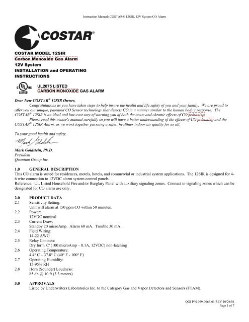
COSTAR MODEL 12SIR Carbon Monoxide Gas Alarm 12V System ...
COSTAR MODEL 12SIR Carbon Monoxide Gas Alarm 12V System ...
COSTAR MODEL 12SIR Carbon Monoxide Gas Alarm 12V System ...

You also want an ePaper? Increase the reach of your titles
YUMPU automatically turns print PDFs into web optimized ePapers that Google loves.
Instruction Manual: <strong>COSTAR</strong>® <strong>12SIR</strong>, <strong>12V</strong> <strong>System</strong> CO <strong>Alarm</strong>Figure 1: Recommended CO alarm placement for singlefloor residence.Figure 2: Recommended CO alarm placement for multilevelresidence.9.5 This CO alarm must be mounted on the wall or ceiling.9.6 WALL LOCATION: Locate the top of the alarm 5 to 6 feet from the floor.Figure 3: Recommended CO alarm mounting location is 5 to 6 feet from floor.8.5 CEILING LOCATION: <strong>Alarm</strong> should be mounted as close as possible to the center of a hallway or room. If this is notpossible, the edge of the alarm should be at least 4 inches from any wall.8.6 LOCATIONS TO AVOIDPlacing units where they will not operate properly causes nuisance alarms. To avoid nuisance alarms, do not place units:– Within 5 feet (1.5m) of any cooking appliance or furnace.– Near an open window or door, because the fresh air entering the opening may delay CO from reaching the alarm.– In damp or very humid areas or next to bathrooms with showers. Install detectors at least 10 feet (3 meters) away frombathrooms.– In very cold or very hot environments or in unheated buildings or outdoor rooms where the temperature can go below orabove the operating range of the alarm. Temperature limits for proper operation are 4.4° C to 37.8° C (40° F to 100° F).– Good ventilation is recommended when household cleaning supplies or similar contaminants are stored or frequently used.8.7 CONDITIONS WHICH CAN RESULT IN TEMPORARY CO SITUATIONS:8.7.1 Excessive spillage or reverse venting of fuel burning appliances caused by outdoor ambient conditions, such as:i) Wind direction and/or velocity, including high gusts of wind. Heavy air in the vent pipes (cold/humid air with extendedperiods between cycles).ii) Negative pressure differential resulting from the use of exhaust fans.iii) Simultaneous operation of several fuel burning appliances competing for limited internal air.iv) Vent pipe connections vibrating loose from clothes dryers, furnaces, or water heaters.v) Obstructions in or unconventional vent pipe designs which can amplify the above situations.8.7.2 Extended operation of unvented fuel burning devices (range, oven, fireplace, etc.)8.7.3 Temperature inversions, which can trap exhaust gasses near the ground.8.7.4 Car idling in an open or closed area garage, or near a home.9.0 INSTALLATION INSTRUCTIONS: CAUTION!! READ CAREFULLY9.1 Select proper location9.2 A mounting plate is provided on the back of the alarm. Remove the mounting plate from the back of the alarm by holdingthe mounting plate and twisting the alarm in the direction indicated by the "OFF" arrow on the alarm cover. (Figure 6)9.3 To insure aesthetic alignment of the alarm with the hallway or wall, the UP ARROW on the mounting plate must be :QGI P/N 099-0066-01 REV 10/26/01Page 4 of 7
Instruction Manual: <strong>COSTAR</strong>® <strong>12SIR</strong>, <strong>12V</strong> <strong>System</strong> CO <strong>Alarm</strong>A.) Parallel with the hallway walls when ceiling mountingB.) Pointed upward when wall mounting9.4 Attach the mounting plate on the wall. Be sure the UP text and arrow are facing up. Use the screws and anchors providedto secure the mounting plate.9.5 WIRING INSTALLATIONInternal terminal block for 14-22 AWG wires. 8 screw terminals at 0.2" (5 mm) spacing.9.5.1 Drill hole in wall or ceiling at center of plate, and pull system wires through the hole.9.5.2 Remove alarm cover by using the special tool provided on the three locking tabs on the alarm base. (see figure 4)Figure 49.5.2 Pull wires through hole at center of alarm base and connect to the internal terminal block as shown on the following wiringdiagrams. (see figure 5)Figure 5NOTE: The form 'C' relay contacts may be wired either N.O. or N.C. according to system panel requirements. These alarms are notdesigned to drive auxiliary devices9.5.4 The <strong>12SIR</strong> alarms do not include power supervision. This may be accomplished by installing a power supervision relay atthe end of the alarm power circuit. No internal backup battery.9.6 Alignment marks are provided on the edge of the trim plate and the alarm. Afterinstalling the mounting plate, place the alarm on the mounting plate with the alignment markslined up. Twist the alarm in the direction indicated by the "ON" arrow on the alarm coveruntil it locks in place.9.7 To make your carbon monoxide alarm tamper resistant, a locking pin has beenprovided in the bag with the screws and anchors. Using this pin will deter children and othersfrom removing the alarm from the mounting plate. To use the pin insert it into the hole in theside of the alarm after the alarm has been installed on the mounting plate (see figure 6). Toremove the alarm, use long nose pliers pull the pin out of the hole; it is now possible toFigure 6remove the alarm from the mounting plate. Test alarm immediately following installation and weekly for proper operation bypushing the test button until a short beep is heard (approximately three seconds). Release the button. The alarm will then test itselfQGI P/N 099-0066-01 REV 10/26/01Page 5 of 7
Instruction Manual: <strong>COSTAR</strong>® <strong>12SIR</strong>, <strong>12V</strong> <strong>System</strong> CO <strong>Alarm</strong>for proper operation and the RED LED will flash 4-6 times. At completion of the self-test, the alarm will sound 2 alarm patterns. Thealarm then resumes normal operation.9.8 This box contains two self-adhesive labels. You should write the telephone numbers of the emergency service provider anda qualified technician in the space provided on the labels. Place one label next to the alarm, and the other label near a source of freshair where you plan to gather after the alarm indicates the presence of carbon monoxide.9.9 Attention Installer: Please leave this manual at residence for user's information.10.0 ALARM SIGNALS10.1 NORMAL OPERATIONRED L.E.D. flashes once every 30 seconds, indicating that the alarm is powered and active.10.2 ALARM CONDITIONRED LED turns "on" for 2 seconds and "off" for 4 seconds with 4 short beeps for 1 second and 5 seconds of silence. TheRED LED will illuminate and the alarm relay will be energized (N.O. or N.C.). Pushing and holding the test/reset button for 3seconds will silence the alarm for about 4 minutes. After 4 minutes, the alarm will once again sound until the unsafe COconcentration is reduced.10.2.1 Connected zone should be programmed for 24 hour monitoring and immediate response for hazardous levels of carbonmonoxide.10.2.2 <strong>Alarm</strong> RELAY output 1 form 'C' dry contacts (non-latching) current capacity is 100 microAmp - 0.1A10.3 TROUBLE CONDITIONThe detector self-tests every 10 minutes. The detector will beep and the Indicator/Test button will flash twice every 30seconds if a fault is detected. This is an indication of a malfunction and that the detector requires immediate servicing.10.3.1 Trouble RELAY output1 form 'C' dry contacts (non-latching) current capacity is 100 microAmp – 0.1ATrouble relay connection to panel is optional.11.0 MAINTENANCECLEANING YOUR ALARM:11.1 Keep your CO alarms clean–do not wash.11.2 To clean your alarm remove it from the mounting bracket as outlined in section 9.2.11.3 You can clean the interior of your alarm by using your vacuum cleaner hose and vacuuming through the openings around theperimeter of the alarm.11.4 The outside can be wiped with a cloth.11.5 After cleaning, reinstall your alarm and test your alarm by using the TEST button.11.6 Test your alarms weekly and repair or replace them when they no longer function. As with any electronic product, alarmshave a limited life and alarms that do not work cannot warn you.WARNING: Do not use any household cleaning agents, paints, varnishes or any other chemical on your <strong>12SIR</strong> alarm.NOTE: REGULAR TESTING IS RECOMMENDED.12.0 PERIODIC ALARM TESTINGTest the alarm weekly for proper operation by pushing the test button until a short beep is heard (approximately three seconds).Release the button. The alarm will then test itself for proper operation and the RED LED light will flash 4-6 times. At completion ofthe test, the alarm will sound 2 patterns. The alarm then resumes normal operation.13.0 SERVICE AND WARRANTYIf after reviewing this manual you feel that your CO <strong>Alarm</strong> is defective in any way, do not tamper with the unit. Before returning thedevice, call Quantum Group's customer service line at 1-800-432-5599 to receive a return merchandise authorization (RMA) number.Once an RMA number has been issued, return the product along with a proof of purchase that includes a date. Please enclose a notedescribing the problem and send it to:7737 Kenamar CourtSan Diego, CA 92121-2425Or call us toll free 1-800-432-5599E-mail address: CustomerService@QGinc.comQGI P/N 099-0066-01 REV 10/26/01Page 6 of 7
Instruction Manual: <strong>COSTAR</strong>® <strong>12SIR</strong>, <strong>12V</strong> <strong>System</strong> CO <strong>Alarm</strong>LIMITED WARRANTY<strong>COSTAR</strong> ® Model <strong>12SIR</strong>Quantum Group Inc. offers you this limited warranty on your new carbon monoxide alarm, including all of its component parts. Thislimited warranty extends solely to the original end-user purchaser of this product, provided your purchase was made from anauthorized vendor. Transfer or resale of this product will automatically terminate warranty coverage.Quantum Group Inc. warrants the enclosed carbon monoxide alarm to be free from defects in materials and workmanship underauthorized use and service, as specified in the owner's manual, for a period of six (6) years from the date of purchase. During theinitial one (1) year period commencing with the date of purchase, any repair or replacement shall be made without charge with proofof purchase. During the latter five (5) years of the warranty period, any repair or replacement shall be made at a charge to thepurchaser not to exceed the manufacturer's cost of repair or replacement. All replaced items become the property of Quantum GroupInc.QUANTUM GROUP INC. MAKES NO OTHER WARRANTIES, EXPRESS OR IMPLIED, EXCEPT AS REQUIRED BY LAW,AND IN NO CASE FOR A DURATION LONGER THAN THAT OF THIS WRITTEN WARRANTY, EXCEPT AS REQUIREDBY LAW, INCLUDING, BUT NOT LIMITED TO, ANY WARRANTY OF MERCHANTABILITY OR FITNESS FOR APARTICULAR PURPOSE OR AGAINST INFRINGEMENT, OR ANY EXPRESS OR IMPLIED WARRANTY ARISING OUTOF TRADE USAGE OR OUT OF A COURSE OF DEALING OR COURSE OF PERFORMANCE. Quantum Group Inc. has notauthorized any other party to extend any other warranties in connection with the sale of the product, and will not accept responsibilityfor any statements, representations, or warranties made by any other person.This limited warranty does not cover: (1) 9 volt alkaline battery (when applicable); (2) products which have been improperly installed,repaired, maintained, modified, or which have been subjected to misuse, abuse, accident, neglect, exposure to fire, water, or excessivechanges in climate or temperature, or combined with non-Quantum Group Inc.-approved accessories; (2) physical damage causedfrom use other than normal and proper operation or handling, as specified in the owner's manual; (3) cosmetic damage; (4) productson which warranty stickers or product serial numbers have been removed, altered, or rendered illegible; (5) the cost of installation,removal or reinstallation.QUANTUM GROUP INC. SPECIFICALLY DISCLAIMS LIABILITY FOR ANY AND ALL DIRECT, INDIRECT, SPECIAL,GENERAL, INCIDENTAL, OR CONSEQUENTIAL DAMAGES, INCLUDING, BUT NOT LIMITED TO, LOSS OF PROFITSOR ANTICIPATED PROFITS ARISING OUT OF USE OF OR INABILITY TO USE THE PRODUCT.QGI P/N 099-0066-01 REV 10/26/01Page 7 of 7